Publisher’s version / Version de l'éditeur:
Vous avez des questions? Nous pouvons vous aider. Pour communiquer directement avec un auteur, consultez la première page de la revue dans laquelle son article a été publié afin de trouver ses coordonnées. Si vous n’arrivez pas à les repérer, communiquez avec nous à [email protected].
Questions? Contact the NRC Publications Archive team at
[email protected]. If you wish to email the authors directly, please see the first page of the publication for their contact information.
https://publications-cnrc.canada.ca/fra/droits
L’accès à ce site Web et l’utilisation de son contenu sont assujettis aux conditions présentées dans le site LISEZ CES CONDITIONS ATTENTIVEMENT AVANT D’UTILISER CE SITE WEB.
Paper (National Research Council of Canada. Institute for Research in
Construction), 1989
READ THESE TERMS AND CONDITIONS CAREFULLY BEFORE USING THIS WEBSITE. https://nrc-publications.canada.ca/eng/copyright
NRC Publications Archive Record / Notice des Archives des publications du CNRC : https://nrc-publications.canada.ca/eng/view/object/?id=12707bff-6be1-49e8-81df-c145d984c487 https://publications-cnrc.canada.ca/fra/voir/objet/?id=12707bff-6be1-49e8-81df-c145d984c487
NRC Publications Archive
Archives des publications du CNRC
This publication could be one of several versions: author’s original, accepted manuscript or the publisher’s version. / La version de cette publication peut être l’une des suivantes : la version prépublication de l’auteur, la version acceptée du manuscrit ou la version de l’éditeur.
For the publisher’s version, please access the DOI link below./ Pour consulter la version de l’éditeur, utilisez le lien DOI ci-dessous.
https://doi.org/10.4224/40001428
Access and use of this website and the material on it are subject to the Terms and Conditions set forth at
Fire resistance of reinforced concrete columns: a parametric study
l f Eier
I1 National Research Conseil national
! l d
1*1
-
Council Canada de recherches Canada Institute for lnstitut deResearch in recherche en
Construction construction
Fire Resistance of Reinforced Concrete
Columns: A Parametric Study
by T.T. Lie
Reprinted from
Journal of Fire Protection Engineering Vol. 1, No. 4, 1989
p. 121-130
(I RC Paper No. 1642)
Des Ctudes exp6rimentales et thbriques ont
Ctt5
men&s pour dlaborer des
dthodes de @vision de la dsistance au feu de colomes de Mton
d.
Dans le cadre de ces etudes, r6ali&s conjointement par le Conseil national
de recherches du Canada et la Portland Cement Association, 41 colomes
ont dt6 rnises
h
l'essai. Les paramhtres Ctudids comprenaient le niveau des
charges, l'importance &s armatures d'acier, la longueur de flambage des
colonnes, la resistance du
Mton,
la teneur en eau,
l'aire
et la forme de la
section, le
type de granulat, la limite axiale de dilatation thermique et
l'excentricig de la charge. Les effets de ces paramhes rdv6lCs par les
exp6riences sont analyds.
J. of Fire Prot. E n g ~ , 7 (4), 1989, pp 121- 130
T.T. Lie
Fire Research Section
Institute for Research in Construction National Research Council of Canada
Ottawa, Ontario, KIA
OR6,
CanadaSUMMARY
Experimental and theoretical studies were carried out to develop general methods for the prediction of the fire resistance of reinforced concrete columns. In these studies, which were carried out jointly between the National Research Council of Canada and the Portland Cement Association, 4 1 columns were tested. The parameters studied included bad level, amount of steel reinforcement, effective length of column, concrete strength, moisture Content, area and shape of cross section, aggregate type, axial restraint of ther- mal expansion and load eccentricity. The experimentally discovered effects of these parameters are discussed.
ufactured by PCA in Skokie, IL, and tested a t the Fire Research Section of NRCC. The results Research on reinforced concrete columnsl~ was of the tests, which have been documented5, will started in Canada in the early 1970's for the be discussed in this paper.
purpose of updating the fire resistance ratings in t h e National Building Code of C a n a d a (NBCC13. This research consisted of theoretical studies, the results of which were compared with those of a limited number of tests carried out in Germany. The studies were initiated in recognition of the fact that the ratings given in the Code for reinforced concrete columns were based on test results obtained in about 1920, and that, since that time, design procedures had changed and safety factors had decreased. The results of this research were incorporated in the NBCC in 1975.
In the late 197OYs, a full-scale column fire test facility4 was constructed a t t h e National Research Council of Canada (NRCC). At that time an extensive program of joint research was established between NRCC and the Portland Cement Association (PCA). The purpose of this research was to re-examine the NBCC ratings, to validate mathematical models that existedbr had to be developed a t that time, and to study the effect of all important variables that affect t h e fire resistance of reinforced concrete columns.
Testing of columns started in 1979. In total, 41 full-scale reinforced concrete columns were tested in the program. The columns were man-
In this study, the effect of the following vari- ables on the fire resistance of reinforced con- crete columns was investigated:
1. load level,
2. percentage of longitudinal reinforcing steel,
3. effective length,
4. concrete strength,
5. relative humidity in concrete, 6. column cross sectional area,
7. column shape (square, circular, or rectangu- lar),
8. concrete aggregate type,
9. axial restraint of thermal expansion, and 10. load eccentricity
The column test specimens were manufactured in three series comprising 12 columns in Series I, 12 columns in Series I1 a n d 17 columns, including the T-series, in Series I11 (Table 1). The various series of columns were constructed in consecutive phases, making use of experience obtained in prior phases. A detailed description of the columns and the materials of which they were composed is given in Reference 5. The
Lie, Fire Resist. Reinforced Concrete Columns: Parametric Study basic properties of the column specimens are listed in Table 1.
Ten of the specimens, which were tested under different loads, were nearly identical and used as reference specimens. These specimens (which are marked with an asterisk in Table 1) were different only in measured concrete strength and relative humidity.
Dimensions
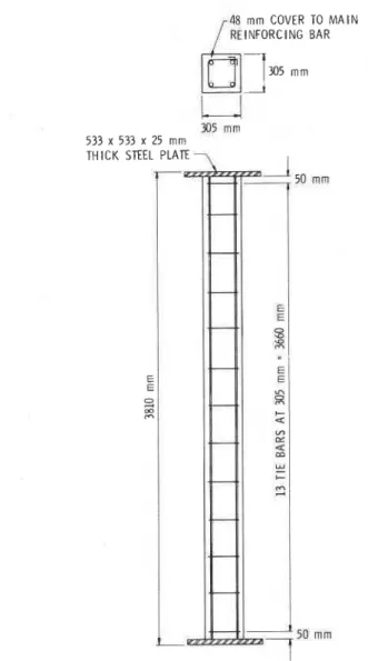
All columns were 3810 mm (12 ft 6 in.) long from endplate to endplate (Figure 1).
The reference cross-section, which is shown in Figure 1, was 305 x 305 mm (12 x 12 in.). Square sections of 203 mm (8 in.) and 406 mm
(16 in.), rectangular sections of 305 x 457 mm (12 x 18 in.) and 203 x 915 mm (8 x 36 in.), and circular sections of 355 mm (14 in.) diameter were also used to investigate the effect of size and shape on fire resistance. All but one column had 38 mm (1.5 in.) cover to the tie bars, and 48 mm (1.875 in.) cover t o t h e vertical steel. Column 11-12 had 64 mm (2.5 in.) cover to the vertical steel. Several 305 x 305 mm (12 x 12 in.) columns were built with brackets for eccen- tric loading (Figure 2).
Concrete Types
Three types of concretes were investigated, i.e., normal weight concretes made with siliceous and carbonate aggregates and a lightweight concrete made with expanded shale aggregate. The concrete of the reference columns was made with siliceous aggregate. The mix of this con- c r e t e w a s designed to produce a concrete strength of 34.5 MPa (5000 psi) a t 28 days after the pouring.
TEST
APPARATUS
AND
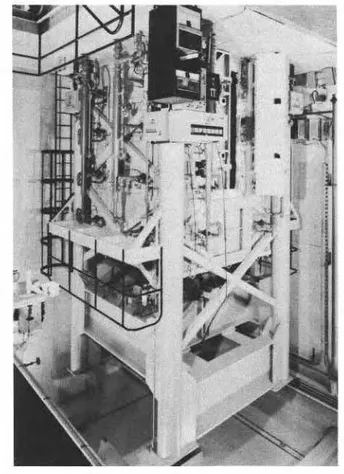
Furnace
The tests were carried out by exposing t h e columns to heat in a furnace especially built for testing loaded columns and walls. The test fur- nace, which uses propane as fuel, was designed to produce the conditions to which a member might be exposed during a fire, i.e. tempera-
tures, structural loads, and h e a t transfer. I t consists of a steel framework supported by four steel columns, with the furnace chamber inside the framework (Figure 3). The characteristics a n d i n s t r u m e n t a t i o n of t h e f u r n a c e a r e described in detail in Reference 4.
Loading
The loads were applied by hydraulic jacks. The main load was provided by a jack acting along the axis of the test column. This jack, which is located a t t h e bottom of t h e column, h a s a capacity of 1000 t.
Most tests were carried out with the ends of the
48 mm COVER TO M A I N /REINFORCING BAR
305 mm 533 x 533 x 25 rnm
THICK STEEL PLATE 7 I
Figure 1. Reference test column and location of rein- forcing bars
J. of Fire Prof. Engs, 1 (4), 1989, pp 121- 130
I
Table
1.
Summary of Test Parameters and Results
1
I
crossI I
Max.
/
Allow.I
Test1I
Failure Section mm 305x305 305x305 305x305 305x305 406x406 203x203 305x305 305x305 305x305 305x305 305x305 305x305R.H. Strength Test Load Load Max. Time
1
9k1
MPaI
kNI
kNI
Load/
hr Test Purpose Standard, dry Load, dry Load Load Sie, dry Size, dry Load Load Load Aggregate Aggregate Aggregate 2.1 9 Sil. 2.1 9 Sil. 2.47 Sil. 2.75 Sil. 2.1 9 Sil. 2.1 9 Sil. 2.1 9 Sil. 2.19 Carb. 2.19 Carb. 2.1 9 Carb. Free translation, fixed-hinged Full axial restraint Full axial restraintHig h-strength concretc
High-strength concretg Aggregate 4Bregate % Steel % Steel Load % Steel % SteeVLoad, thick cover Fixed-hinged Fixed-hinged Ecc. load (24mm), hinged-hinged Fie intensity Shape-rectangular Shape-mini-wall Ecc.load, partial rotation Ecc.load, rotation const. Ecc.lod, rotation const. Ecc.load, load const. Shapecircular Shapecircular Room-temp. crush Ecc.load (24 mm) fixed-hinged Residual strength 1 hrfire Residual strength Sil. Sil. Sil. Sil. Sii. Shale Shale Sil. Sil. Sil. Sil. Sil. Sit. Sil. Carb. Carb. Sit. Sil. Sil. Sil. Sil. Sil. Sil. Sil. Sil. Sil. Sil. 2 hr fire 305x305 2.19 Sil. Hingd-hinged 305x305 2.19 Sil. Reference columns
Test was stopped due to air fan burnout Column with brackets
Initial load/maxirnum load
Initial eccentric loadleccentrii load at end of test Residual strength (kN)
Lie, Fire Resist. Reinforced Concrete Columns: Parametric Study
columns fixed, but different effective lengths "Design of Concrete Structures for Buildings" were obtained in some tests by pinning the top ( c A ~ 3 - A 2 3 - M 8 4 ) 6 or t h e "Building Code end (111-1, 111-2) or both ends (T-3), or by pin- Requirements for Reinforced Concrete" (ACI ning the top end and allowing it to move hori- 318-83), adopted as a standard by the American
zontally (11-1). Concrete Institute7.
Six columns were tested under an eccentric load. In two tests the eccentric load was applied by offsetting the column by 24 mm (111-3, III- 14). Four tests were carried out on columns with brackets (111-7 to 111-10). In these tests the eccentric loads were applied by two additional jacks located at 508 mm from the centre of the column (Figure 2). In two of these tests the ini- tial rotation of the brackets (after loading) was kept constant to simulate full restraint against rotation of the ends (111-8, 111-9); in one test the eccentric loads were kept constant to simulate no restraint against rotation (111-10); in one test the eccentric loads were gradually reduced, from 49 t o 32 kN at a rate of 1 kN per 10 min- utes, to simulate partial restraint against rota- tion (111-7).
The load level in the various tests varied from zero to higher than the maximum allowable load calculated according to acceptable design standards, i.e., the Canadian National Standard
AXIAL ECCCENTRIC LOAD
C=F-==-7
AXIAL LOAD ECCENTRIC LOAD
Fire Exposure
Most columns were exposed to the ULC-S101 (ASTM-E119)89 9 standard fire. TWO columns (T-
1, T-2) were exposed to a standard fire6> for limited periods after which the columns were cooled down and crushed for the purpose of determining t h e residual s t r e n g t h s of t h e columns. One column (111-13) was crushed a t room temperature for the purpose of verifying the accuracy of the calculated initial strength of the column. Another column (1114) was subject- ed to a high-intensity fire, which simulated a hydrocarbon oil pool fire5.
Failure Criterion
In all tests the columns were considered to have
J. of Fire Prot. Engs, 1 (4), 1989, pp 121- 130 failed, and the tests were terminated, when the tance. The effect of doubling the reinforcement main hydraulic jack, which has a maximum speed from 2.19% in the reference columns
to
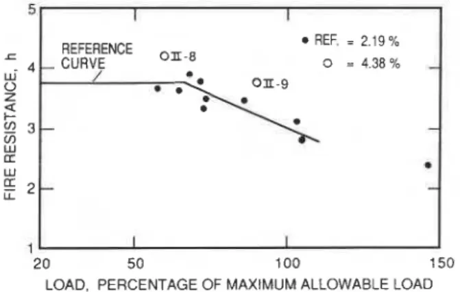
4.38% of 76 mmlmin, could no longer maintain the load. (11-8 and 11-91 is about 10%.The influence of the various study variables on the fire resistance of the columns is shown in Figures 4-13 and summarized in Table 1.
In Figure 4 the fire resistances of the ten refer- ence columns, tested under various loads, and a reference curve reflecting the fire resistance of these columns a s a function of the load, are shown. As expected, the fire resistance increas- es with reduction of the load. In the range of loads investigated, i.e. from about 100 to 50 per- cent of t h e maximum allowable load, t h e increase in fire resistance is about 25 percent. Also in Figure 4, the current fire resistance rat- ings permitted in the NBCC and the proposed ratings for the next NBCC, which are substan- tially less conservative, are shown.
The influence of the various study variables can be assessed by comparing the fire resistances, measured under the various conditions studied, with the reference fire resistances. These com- parisons are made in Figures 5-13 for the fol- lowing variables:
1.
Percentage of Reinforcement
The results (Figure 5) indicate that increasing the reinforcement will increase the fire resis-
REFERENCE OF FIRE RESISTANCES REFERENCE COLUMNS
4 - CURVE w- 0 *. Z
3
V, 3 - PROPOSED NBCC':<
V) CURREWNBCC W 2 - 1 1 I 20 50 1 00 I!LOAD, PERCENTAGE OF MAXIMUM ALLOWABLE LOAD
2.
Effective Length
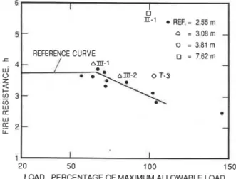
The effect of column effective length is shown in Figure 6. Theoretically, i t is expected that for the same load and column section the fire resis- tance will decrease with increase of effective length. The maximum allowable load, however, also decreases with increase of effective length. The results indicate that the effect of decrease in load more than compensates for the effect of increase of effective length, resulting in a n increase of fire resistance. Especially for longer columns, the increase is substantial (11-1). For this column, for example, the maximum allow- able load reduces to 342 kN from about 1350 kN, when t h e column effective length i s increased from 2.55 to 7.62 m. This large reduc- tion in load apparently more than compensated for the unfavorable effect of increase of column length, resulting in an increase of fire resis- tance from about 3.5 h r to almost 5 hr.
3.
Concrete Strength
The influence of concrete strength is shown in Figure 7, where the fire resistance of the two columns made with a high strength siliceous aggregate concrete (50 MPa) are compared with the reference fire resistances. Because the load on these columns (11-4, 11-5) was increased in accordance with the higher strength of the
a r REF. = 2.19 %
) E - 8
.
O = 4.38 % O n - 9I I
I
j0 20 50 100 150
LOAD. PERCENTAGE OF MAXIMUM ALLOWABLE LOAD Figure 4. Fire resistances of reference columns and
Lie,
Fire
Resist. Reinforced Concrete Columns: Parametric Studycolumns, there was no significant increase in the fire resistance of the columns.
may in the practical region, i.e., a moisture con- dition a t equilibrium in air of 50 to 75% R.H. a t about 20°C, be neglected.
4.
Relative Humidity
In Figure 8, the fire resistance of a nearly dry column (1-2) is compared with that of a similar column (1-9) with a normal concrete moisture condition (75% R.H.). The test results as well as results of theoretical studies carried out earli- erlO showed that the influence of the moisture content of the concrete on the fire resistance of the column is small. Variations of fire resis- tance, due to variations of moisture content,
6 I I D REF. = 2.55 m 5
-
a = 3.08 m - a = 3.81 m 1 REFERENCE CURVE = 7,62 m 4-
nm-1 - w- 0 Z2
cn 3 - - V) W IT Wg
2 - - 2 0 5 0 1 0 0 1 5 0LOAD, PERCENTAGE OF MAXIMUM ALLOWABLE LOAD
Figure 6. Influence of effective length
5.
Column Cross Sectional Area
Figure 9 illustrates the influence of the cross sectional area of the column on its fire resis- tance. The test results indicate t h a t column cross section has a large influence on the fire resistance of the column. Under commensurate loading, the fire resistance increased by about 30% by doubling the area. For one column (II-
11) the increase was over 4%, but in this case, part of the increase was probably caused by the significantly higher percentage of steel rein- forcement in this column.
6.
Column Shape
The influence of column shape, i.e. square, cir- cular or rectangular, on the fire resistance of the column is illustrated in Figure 10. The columns with rectangular cross section (111-5, 111-6) have under commensurate loading substantially higher fire resistance than those with square cross section with the same thickness. The fire resistances of the columns with rectangular cross section are about 50% higher than those of the columns with square cross section with equal thickness. The reason for the substantial difference in fire resistance is probably that the heating of the core of columns with rectangular cross section approaches that of a wall, which is heated-on two sides, whereas the columns with
5 REF. = ABOUT 35 MPa
O = ABOUT 50 MPa c 4 w- 0 Z a $ 3 V) w u W
g
2 1 2 0 5 0 1 0 0 1 5 0 20 5 0 1 0 0 150LOAD. PERCENTAGE OF MAXIMUM ALLOWABLE LOAD LOAD. PERCENTAGE OF MAXIMUM ALLOWABLE LOAD
I REF. = 75 % R.H. REFERENCE CURVE @ = 1 5 % R.H. - - - 1-2 rn - - I I
J. of Fire Prot. Engs, 1 (4), 1989, pp 121- 130
square cross section are heated on four sides. The fire resistances of columns with circular cross section (111-11, 111-12) were 5-10% higher than those of columns with square cross section with approximately the same area. Because in fact the cross sectional area of the columns with circular cross section was about 7% greater than that of the columns with square section, the dif- ference in fire resistance of 5-10% can be regarded as insignificant.
7.
Aggregate Type
The results of tests on columns made with car- bonate aggregate concrete (1-10, 1-11, 1-12) and on columns made with expanded shale aggre- gate concrete (11-6,II-7) are shown in Figure 11.
It can be seen that the carbonate aggregate con- crete columns have extremely high fire resis- tances as compared to the reference columns which were made with siliceous aggregate. For example, the carbonate aggregate column (1-11) had a fire resistance of more than 6 hr, whereas the fire resistance of the comparable siliceous aggregate concrete column was about 3.5 hr.
I I 1 REF. = SQUARE (305 x 305 mm) - m-5 = RECTANGULAR (305 x 457 0 = RECTANGULAR (203 x 915 $6 0 = CIRCULAR (DIA355 mm) - I I I l I - 1 1 REFERENCECURVE l I - 1 0 n - 1-6 0 - REF. = 305 x 305 mm (2.19 % STEEL) o = 203 x 203 mm (2.75 % STEEL)- n = 406 x 406 mm (2.47 %STEEL) 3 = 406 x 406 mm (3.97 % STEEL) I I 1 I 1 I
1
2 0 5 0 1 0 0 1 5 0LOAD, PERCENTAGE OF MAXIMUM ALLOWABLE LOAD
Figure 10. lnfluence of column shape
9 The fire resistances of the columns made with
expanded shale aggregate are about the same
as those of the reference columns. 8
1
20 5 0 1 0 0 150 1
LOAD, PERCENTAGE OF MAXIMUM ALLOWABLE LOAD 2 0 5 0 ' 1 0 0 t 50 LOAD, PERCENTAGE OF MAXIMUM ALLOWABLE LOAD
I I a REF. = SILICEOUS 1-10 a = CARBONATE -
-
o-
EXPANDED SHALE-
- A 1 - 1 1-
- - - REFERENCE %-7 CURVE --
/ 1 - 1 2 D - --
- I IFlgure 9. Influence of cross sectional area
Lie, Fire Resist. Reinforced Concrete Columns: Parametric Study
8.
Restraint of Axial Thermal
Expansion
To investigate the possible detrimental effect of restraint of thermal expansion, two columns (II- 2, 11-31 were tested under full restraint, i.e., expansion of the column was prevented during the tests by application of additional load that kept the length of the column constant with a precision of k0.002 mm. The results, which are shown in Figure 12, indicate that restraint of axial thermal expansion does not reduce the fire resistance of the column although the load tem- porarily increased to more than twice the initial load during the tests.
9.
Load
Eccentricity
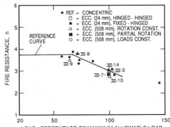
The results of tests on six eccentrically loaded columns are shown in Figure 13. The eccentricity of the load was that required by the ACI 318 Code6 and the CSA A23.3 Standard7 for concentri- cally loaded columns. In the case of the columns studied, the eccentricity equates to 24 mm. This was obtained by offsetting the load 24 mm from the centre of the column section (111-3, 111-141, or by applying the appropriate eccentric load on the columns with bracket a t a distance of 508 mm from the centre of the column section (111-7 to III- 10). One of the columns was made with carbonate aggregate concrete (111-3). The others were made with siliceous aggregate concrete.
The reduction in fire resistance due to eccentric loads was the highest for the carbonate aggre- gate column (111-3). The reduction in fire resis- tance for this column was approximately 40% when compared with the fire resistance of con- centrically loaded carbonate aggregate concrete columns (see Figure 11). For the siliceous aggre- gate concrete columns, the highest reduction in fire resistance due to eccentric load was approx- imately 10% (111-10). This reduction was found in the test, in which the eccentric load was kept constant, simulating the worst case that the surrounding structure provides no restraint against rotation of the ends of the column. In all other cases there was no pronounced effect of load eccentricity.
CONCLUSIONS
Of the variables studied in the NRCCIPCA study program, load, cross sectional area for similar shapes, and type of aggregate have the largest influence on the fire resistance of reinforced con- crete columns. Particularly the use of carbonate aggregate, instead of siliceous aggregate, will sub- stantially increase the fire resistance of the column. Rectangular columns also produced fire resistances that are substantially higher than those of square columns of same thickness.
REF. = NO RESTRAINT
I
@ = FULL RESTRAINT
i
1 1 I I
I
20 50 100 150
LOAD. PERCENTAGE OF M A X I M U M ALLOWABLE LOAD
' REF. = CONCEMTR~C
o = ECC. 124 mml. HINGED - HINGED
I
-
A = ECC. (24 mmj: FIXED - HINGEDn = ECC. (508 rnrrt), ROTATION CONST. CURYE
20 50 100 150
LOAD. PERCENTAGE OF M A X I M U M ALLOWABLE LOAD
Figure 13. lnfluence of load eccentricity Figure 12. lnfluence of restraint of axial expansion
J. of Fire Prot. E n g ~ , 1 (4), 1989, pp 121
-
130Increase of the amount of reinforcing steel and Resistance of Columns, Canadian Journal of effective length of the columns produce relative- Civil Engineering, Vol. 7, 1980, pp. 551-558. ly small increases in fire resistance, if a load is 5. Lie, T.T. a n d Woollerton, J.L., F i r e applied that is commensurate with the increase Resistance of Reinforced Concrete Columns: of amount of steel a n d column length. Test Results, National Research Council of Application of small eccentric loads causes a C a n a d a , I n s t i t u t e for Research i n
small reduction in fire resistance. Construction, Internal Report No. 569,
Ottawa, Canada, July 1988. The influence of concrete strength, concrete
moisture content and restraint of axial column expansion is insignificant.
The fire resistances of the columns studied are considerably higher than those assigned to them in the National Building Code of Canada3 and in the American Concrete Institute Guide 21611. The difference is mainly caused by the substantial increase in experimental and theo- retical data, which enables a less conservative approach in establishing fire resistance ratings. New ratings, based on the results of this study, will be incorporated in these documents.
Although a large number of tests were carried out, they do not provide sufficient information on fire resistance for many values of the vari- ables beyond the values studied in the tests. They provide basic data, however, that enable the development and validation of mathemati- cal models capable of calculating fire resistances for any value of the variables in the practical range. The development of such models is now in an advanced stagelo.
REFERENCES
1. Lie, T.T. and Allen, D.E., Calculations of the Fire Resistance of Reinforced Concrete Columns, National Research Council of Canada, Division of Building Research, NRCC 12797, Ottawa, Canada, August 1972.
2. Allen, D.E. and Lie, T.T., Further Studies of the Fire Resistance of Reinforced Concrete Columns, National Research Council of Canada, Division of Building Research, NRCC 14047, Ottawa, Canada, June 1974. 3. The National Building Code of Canada
1985, National Research Council of Canada, Associate Committee on t h e National Building Code, Ottawa, Canada, 1985. 4. Lie, T.T., New Facility to Determine Fire
6. Building Code Requirements for Reinforced Concrete, ACI Standard 318-83, American Concrete Institute, Detroit, MI, 1983. 7. Design of Concrete Structures for Buildings,
CAN3-A23.3-M84, Canadian Standards Association, Rexdale, Ontario, 1984.
8. Standard Methods of Fire Tests of Building Construction a n d Materials, E119-83, American Society for Testing and Materials, Philadelphia, PA, 1985.
9. Standard Methods of Fire Endurance Tests of Building Construction a n d Materials, Underwriters' Laboratories of Canada, CAN4-S101-M82 Scarborough, Canada, 1982,.
10. Lie, T.T., Lin, T.D., Allen, D.E. and Abrams, M.S., Fire Resistance of Reinforced Concrete Columns, National Research Council of Canada, Division of Building Research, NRCC 23065, Ottawa, Canada, February
1984.
11. Guide for Determining the Fire Endurance of Concrete Elements, ACI 216R-87, American Concrete Institute, Detroit, MI,