Eur Radiol (2006) 16: 2875–2878 DOI 10.1007/s00330-006-0467-z T I P S A N D T R I C K S Stefano Binaghi Daniel Guntern Pierre Schnyder Nicolas Theumann Received: 1 May 2006 Revised: 4 August 2006 Accepted: 25 August 2006 Published online: 13 October 2006 # Springer-Verlag 2006
A new, easy, fast, and safe method
for CT-guided sacroplasty
Abstract Sacral insufficiency frac-tures constitute clinical challenges because no effective surgical tech-niques can be applied and only a conservative treatment is currently performed. Sacroplasty is increasingly used to treat sacral insufficiency fractures. A computed tomography (CT)-guided technique concerning the placement of the sacroplasty needles within the sacral wings by using a laser alignment light guidance asso-ciated with a CT gantry tilt in a plane parallel to the sacral bone is presented. This method allowed a fast and precise placement of the needle in and along the sacral wings, thus preventing the use of multiple needles to reach the fracture sites.
Keywords Sacroplasty .
Vertebroplasty . Sacral insufficiency fracture . Acrylic cement . Computed tomography guidance
Introduction
Sacral insufficiency fractures are relatively common and are often associated with severe and debilitating pain. They are caused mainly by osteoporosis, rheumatoid arthritis, and radiation therapy to the pelvis [1]. Techniques developed specifically for vertebroplasty have been extended to treat sacral insufficiency fractures, and this procedure was called “percutaneous sacroplasty.” It was developed because there is actually no effective surgical techniques available to immobilize and fix the sacral bone in case of sacral insufficiency fractures. Moreover, the only alternative treatment is conservative and is constituted by bed rest, which can severely invalidate the patient. Percutaneous sacroplasty can fix the sacral fracture site and may provide symptomatic relief and hasten recovery [2, 3]. Sacroplasty is usually performed under computed tomography (CT) guidance, as in our institution, although in some centers it is performed under biplane fluoroscopy. When performing a CT-guided sacroplasty, the curved
shape of the sacral bone prevents visualization of the complete superior–inferior extent of the fracture in the conventional axial plane. Therefore, it is difficult to achieve a working projection that is adequate enough to ensure that the path of the percutaneous needle will be in the same plane as the fracture lines and pass through the fourth to the first sacral bodies. In the best setting, the needles should be completely visible during their place-ment and should be precisely advanced from the inferior to the superior aspect of the fracture site without compromis-ing the sacroiliac joints and the sacral foramina. The main advantages would be the use of a single needle instead of multiple needles when treating a single fracture. This increases the safety and reduces the time required for the procedure. Consequently, we developed a CT-guidance approach dedicated to the needle placement phase of the sacroplasty. This approach is characterized by a CT gantry tilt parallel to the fracture plane associated with external guidance of the needle using the laser alignment light provided by the CT unit. The successive injection of S. Binaghi . D. Guntern . P. Schnyder .
N. Theumann
Department of Diagnostic and Interventional Radiology, University Hospital,
1011 Lausanne, Switzerland
S. Binaghi (*)
Service de Radiodiagnostic et radiologie interventionnelle, Unité de Neuroradiologie, Centre Hospitalier Universitaire Vaudois (CHUV), Rue du Bugnon,
1011 Lausanne, Switzerland e-mail: [email protected] Tel.: +41-21-3144397
polymethylmethacrylate (PMMA) into the fracture site is then be performed after verticalization of the CT gantry to allow repetitive helical acquisitions.
Description of the technique
The procedure includes a standard prone positioning of the patient in the CT unit under conscious sedation with midazolam. CT-scan data are obtained with an eight-row CT unit (Lightspeed Ultra; GE Medical Systems, Milwau-kee, WI, USA). The area to be treated is prepared in a strictly sterile manner, and a local anesthesia is used. The first part of the CT guidance dedicated to the placement of the needle is set in incremental mode, with tilting of the CT gantry in a plane as parallel as possible to that of the body of the sacrum, in order to visualize the complete intraos-seous path along which the needle has to be advanced (Fig. 1a). The vertical position of the sacral bone can be adjusted in order to fit the tilting limits of the CT gantry by placing specific positioning pillows under the patient’s thighs or knees. After a small skin incision, an 11gauge vertebroplasty beveled needle (OsteoSite Bone Biopsy Needle Set, Cook, Bjaeverskov, Denmark) is positioned at the entry point in the sacrum. Then, the needle is inclined, directed, and advanced according to the laser alignment light of the CT unit in order to achieve precise control of the access between the sacroiliac joints and the sacral foram-ina, going from the inferior aspect to the superior aspect of the fracture, mostly bilaterally (Fig.1b and c). In this way, the needle is completely visible on the same CT slice until its final positioning is achieved. The successive injection of PMMA is performed in helical mode, with the CT gantry in a vertical position. Two 10-ml high-pressure injector sets (OsteoForce, Cook, Bjaeverskov, Denmark) are simulta-neously used by two operators on both sides of the fracture for the injection of PMMA (Vertebroplastic, DePuy Acromed Inc, Raynham, MA, USA). An average of 6 ml of PMMA is delivered on each side of the fracture; the
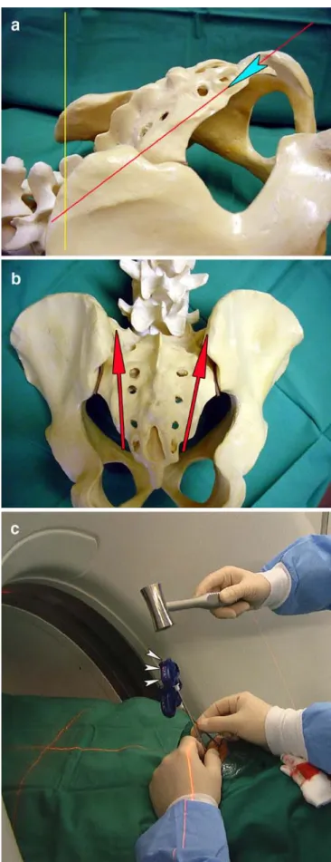
" Fig. 1 a Schematic image using an artificial model of the hip in lateral view showing the tilting of the computed tomography (CT) gantry for positioning the sacroplasty needles. The gantry is inclined from the vertical position (yellow line) toward the long axis of the sacral bone (red line); the angle of the gantry corresponds to the angle formed between the two lines. The laser alignment light is represented by the red line, and the entry point of the needle is represented by the blue arrowhead. b Schematic image in antero-posterior view showing the route of access of the sacroplasty needles. The needles are inserted at the level of the third or fourth sacral level and follow a caudo-cranial direction according the laser alignment light toward the superior aspect of the sacral ala. The path of the needles (red arrows) is located between the sacral foramina and the sacroiliac joints. c Intraoperative image showing the use of the inclined CT gantry during placement of the needles and their advancement by using the laser alignment light of the CT unit; the proximal extremity and the shaft of the needle is always kept centered on the guiding laser beam (arrowheads), ensuring the correct direction dictated by the inclined CT gantry
injection is carried out very slowly with constant checking for an eventual cement leakage toward the sacral foramina or the sacroiliac joints. If a leakage is going to appear, the bevel of the needle has to be directed to the opposite direction of the leakage or the needle has to be slightly withdrawn. During PMMA administration, the needles are progressively withdrawn from the first sacral level toward the entry point located on the third or fourth sacral level, under intermittent observation by successive helical CT series, in order to fill the entire length of the fracture. Using this technique, six patients with sacral insufficiency fractures were treated at our institution, and no procedural complications were noted. Here, one illustrative case is reported.
Case report
A 68-year-old woman with a history of lymphoma was admitted for intractable left sacral pain after a fall. She rated the pain 10 out of 10 on a Visual Analog Scale (VAS) scale. The patient had no neurosensory deficit and was bedridden secondary to her pain, which was refractory to more than 4 weeks of medical treatment. An H-shaped sacral insuffi-ciency fracture was disclosed by magnetic resonance
imaging (MRI) (Fig. 2). Because of the severity of the symptoms, the patient agreed to undergo a sacroplasty treatment. The procedure was performed under local anesthesia by using 10 cc of 1% lidocaine administered bilaterally. CT guidance was performed, as described in the previous paragraph, using a tilted gantry position during needle positioning and a vertical position during PMMA administration. The PMMA filled the fracture site without local complications or neural foraminal leakage. The following day, the patient indicated clear pain relief (VAS scale 2/10). The patient continued to rehabilitate, discon-tinued her analgesic medications the following week, and was discharged to go home where she resumed an independent lifestyle.
Discussion
The availability of techniques designed for use in percu-taneous vertebroplasty has enhanced the ability to treat sacral insufficiency fractures in a similar way [2, 3]. Indeed, there are actually no other surgical or interventional options to achieve treatment of these kinds of fractures, and the only alternative to sacroplasty remains conservative treatment with bed rest and immobilization. Appropriate
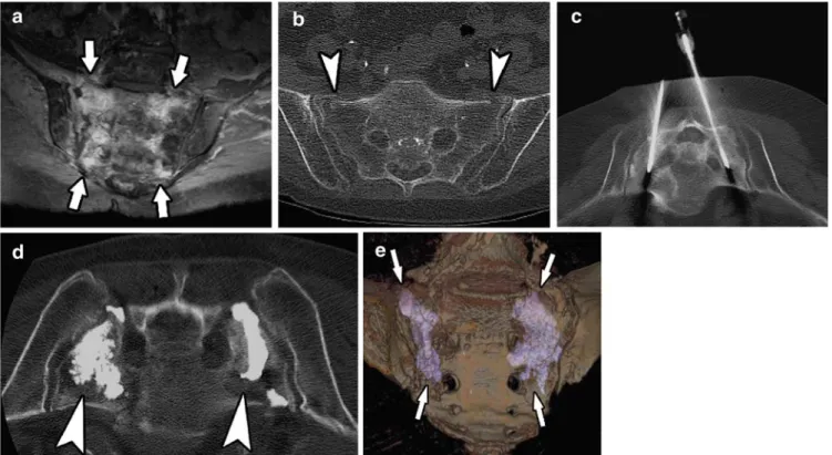
Fig. 2 a Axial T2-weighted magnetic resonance image (MRI) showing bone marrow edema within both sacral wings correspond-ing to the fracture sites (arrows). b Computed tomography (CT) scan showing bilateral sacral insufficiency fractures (arrowheads). c CT image in the inclined plane with the patient being positioned prone, showing the two sacroplasty needles on each side of the
sacrum advanced along the fracture lines. d CT image in the axial plane guiding the bilateral delivery of PMMA at the distal end of the needles (arrowheads). e Postprocedure three-dimensional (3D) volume-rendered CT segmentation of the sacral bone illustrating PMMA filling bilateral fracture sites (arrows)
needle approach and placement is of paramount importance when performing vertebroplasty and sacroplasty. Previous technical reports describe needle insertion techniques along the long axis of the sacrum (parallel to the dorsal cortex of the sacrum) or along its short axis (perpendicular to the dorsal cortex of the sacrum); both techniques can be performed under fluoroscopy or CT guidance [2, 3]. Because of the inability to completely visualize the path of the fracture during the positioning of the sacroplasty needles in the short axis plane, multiple needles are frequently used with this technique to achieve a complete percutaneous approach to reach all parts of the fracture, which can be time consuming and uncomfortable for a patient, who is treated under local anesthesia. Thus, the ideal procedure would consist of a single, long-axis approach on each side of the fracture, taking into account the curved shape of the sacral bone. The path of a single needle has to be planned along the fracture line in order to successively cross the fourth, third, second, and first sacral bodies, corresponding to the main extension of the fracture. This can be more easily performed under CT guidance than under conventional fluoroscopy. Our long-axis CT ap-proach to sacral fractures implies the use of the CT gantry in a tilted position in association with laser alignment light guidance when advancing the needle. Indeed, the use of the conventional vertical position of the CT gantry implies visualization of the needle path in a near the short-axis plane, thus not in the same plane as the fracture. An in-plane route is preferable to an out-of-in-plane route in order to avoid the use of multiple needles to encompass the entire extension of the fracture. Moreover, multiple attempts may be necessary in the axial plane before reaching the correct position of the tips, thus resulting in a risk of cement leakage along the previous needle tracks [4]. Our proposed inclined approach implies incremental scanning because helical acquisition is allowed only in the axial plane. When using CT fluoroscopy, CT guidance will be helical and possible only in the axial plane so that needle placement will present the same drawbacks as with conventional CT units, suggesting that an inclined approach could be used during needle placement even in this setting, followed by cement delivery under CT fluoroscopy. In our experience, the duration of positioning the bilateral needles in the sacral
fractures never exceeded 15 min, and the entire procedure lasted 45–60 min for each patient, including the installation phase. We have not experienced difficulties with this technique; indeed, the procedure was easier, faster, and intuitively safer in comparison with conventional CT guidance. The average volume of injected PMMA was 12 ml (6 ml on each side of the fracture). The potential risks of this sacroplasty technique include cement extrusion into the sacral foramina or into the sacroiliac joint, and penetration of the superior margin of the sacral ala. We always perform a CT scan of the sacrum before the procedure to check the integrity of the osseous walls of the sacral foramina and to identify the eventual extension of the fracture line toward the sacroiliac joint or the sacral foramina, in order to avoid excessive PMMA injection near those involved structures. We experienced one minor leakage of PMMA in one of our six patients, occurring through the fracture site toward the first and second right sacral foramina. It was, however, immediately treated according to the“cooling system” described by Kelekis et al. [5], consisting of the injection of 20 ml of saline around the first and second right sacral roots. No radicular pain resulted from these neural foraminal leaks. Pain relief was apparent in all patients by the time of discharge from the hospital.
Conclusion
The technique described above allows complete visualiza-tion of the sacroplasty needles during their posivisualiza-tioning in the sacral bone marrow by using a working projection at CT guidance parallel to the first, second, and third sacral bodies and by advancing the needles under laser alignment light guidance. This technique should reduce the number of needles used and provide precision, safety, and speed to the procedure. It should also facilitate the technical realization of a sacroplasty, even when a CT fluoroscopy unit is available.
Acknowledgment We gratefully acknowledge the assistance of Keith Brooks, PhD, for his help in editing the manuscript.
References
1. De Smet AA, Neff JR (1985) Pubic and sacral insufficiency fractures: clinical course and radiologic findings. AJR Am J Roentgenol 145:601–606 2. Butler CL, Given CA, Michel SJ, Tibbs
PA (2005) Percutaneous Sacroplasty for the treatment of Sacral Insufficiency fractures. AJR Am J Roentgenol 184:1956–1959
3. Pommersheim W, Huang-Hellinger F, Baker M, Morris P (2003) Sacroplasty: a treatment for Sacral Insufficiency fractures. AJNR Am J Neuroradiol 24:1003–1007
4. Laredo JD, Hamze B (2004) Compli-cations of percutaneous vertebroplasty and their prevention. Skeletal Radiol 33:493–505
5. Kelekis AD, Martin JB, Somon T, Wetzel SG, Dietrich PY, Rüfenacht DA (2003) Radicular pain after vertebro-plasty: compression or irritation of the nerve root? Initial experience with the “cooling system”. Spine 28:E265–E269 2878