Non-linear Finite Element Analysis of Intramedullary Implants for
Proximal Femoral Fractures
Brunner P., Frei Hp., Nolte L.-P.
M.E. Müller-Institut für Biomechanik Universität Bern, CH-3010 Bern, SchweizINTRODUCTION
Proximal femoral fractures are common in the elderly and their operative treatment is controversial. Achievement of bony union and allowance of immediate füll weightbearing place high demands on implants. Intramedullary (IM.) nails have been the method of choice in modern fracture treatment, but in some cases such implants have catastrophically failed [1]. Implant design greatly influences the survival rate of such an osteosynthesis. One of the weak points of IM nails is around the insertion hole for the lag screw where the cross-sectional area is reduced and bending moments are large. Stresses during ambulation become large enough to cause metal fatigue fractures.
Within this study 2D and 3D finite element models were generated to investigate the stress state of particular design components of a prototype IM nail in comparison to the widely used Gamma Nail (Howmedica). A variety of design parameters such äs screw and nail diameter were optimized aiming at minimal stress concentrations in the screw-nail junction.
METHODS
Based on geometrical data of a clinically used IM nail System (Gamma Nail) solid models were generated with the CAD Software I-DEAS Master Series 2.1 (SDRC). Manufacturing tolerances of 0.1 mm for the diameters were taken into account. Further preprocessing was done with the MENTAT (MARC Analysis Research Corp.): Material properties were assigned either for a titanium alloy or stainless steel (Young's moduli: ETAN=HO GPa, Esteci=190 GPa). All materials were assumed to behave in a linear elastic, homogeneous and isotropic manner. Poisson's ratio was 0.3 in all materials. Solving of the non-linear contact problem (non-linear boundary condition) was performed with the general purpose finite element analysis Software MARC K6.1 (MARC) and its automated contact analysis capability. Interfaces were assumed unbounded with no friction. Incremental loading allowed for detection of contact nodes and analysis of large displacements. Springs with low stiffhess were introduced to prevent rigid body motion of the deformable bodies.
2D Analvsis of femoral neck screw
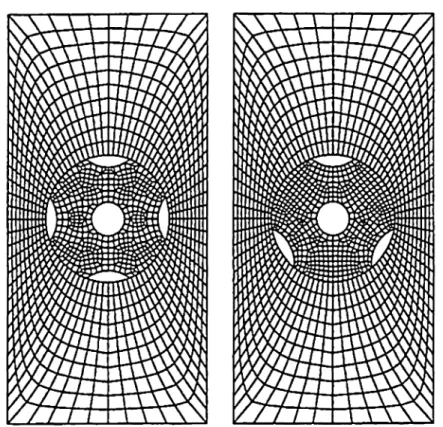
Notches along the surface of the femoral neck screw are designed to prevent rotational instability of the screw within the IM nail and the proximal femoral fragment. The Standard configuration with four notches may lead to stress concentrations in the IM nail. In a plane strain
analysis we investigated the effect of three versus four notches on the load transfer to the IM nail under cranio-caudal loading. The geometry for the two designs was meshed using quadrilateral elements (Fig. 1). Due to symmetry only half of the geometry was modeled and calculated.
Fig. 1: 2D FE model of the femoral neck screw (Lefi: Four notches; Right: Three notches)
3D Analvsis of proximal IM nail
The focus of this study was the proximal junction of nail(s) and screw(s). Gamma Nail and prototype IM nails with one or two femoral neck screws were modeled (Fig. 2). The FE meshes were realized with 8-node hexahedral elements (neck screw) and 4-node tetrahedrals (IM nail). The Simulation was carried out with three-dimensional models symmetrical to the mid-frontal plane. The nails were distally fixed, i.e. clamping boundary conditions were imposed far enough frorn the interest zone. The loading condition was modeled according to a worst case scenario where load-sharing by bony support was not possible and maximum hip joint force was acting at the dp of the implant. Incremental loading was applied to a maximum load of 3000 N with a 20° inclination due to orientation of joint reaction force and femur adduction in single leg stance. A preliminary analysis for comparative evaluation of the two implant concepts was mn for a variety of nail and screw diameters with approx. 4500 elements in each model. A number of fine-tuning runs were performed with a high mesh density (approx. 8000 elements/model) in the area of contact. After the
preliminary analyses we focused on a prototype implant with a 17mm IM nail and different screw diameters (llmm, 11.25mm, and 11.50mm). Equivalent von Mises Stresses were plotted for comparative evaluation of the modeled designs. The data was analyzed at three different loads (1000, 2000 and 3000N) in Order to simulate the stress distribution in the implants at different magnitudes of physical activity postoperatively.
Fig. 2:3D FE model ofthe proximal IM nail (L: Gamma Nail; R: Prototype nail)
RESULTS
2D Analvsis of femoral neck screw
For comparative analysis of the results equivalent von Mises stress path plots along the distal edge of the hole in the IM nail were plotted. The screw with three notches induced significant stress concentrations in the IM nail at the edge of the distal notch. The plots clearly demonstrated the potential for reduction in stress concentration by modification of the configuration (number and placement) of the notches (Fig. 3). The selection of the material (TAN or steel) did not have any influence on the stress distribution the load transfer zone.
Fig. 3 The path plot along the edge ofthe hole in the IM nail depicts peak equivalent von Mises Stresses [MPa] (Leß: Four notches; Right: Three notches).
3D Analvsis of proximal IM nail
In order to present the results at the joint interface several groups of nodes were selected on the IM nail surface. The most critical area was the anterior and posterior edge on both the medial or lateral exit of the of the hole passing through the IM nail (Location a and b in Fig. 4).
The numbers for these locations and three loading magnitudes are given in Table 1. The prototype IM nail with a proximal diameter of 17 mm and a 11.25mm diameter for the larger femoral neck screw (P-17-11.25) showed the stress distribution with the lowest stress values in the critical area.
FigA:Area of interest that has been analyzed for comparison of the strain distribution of different implant configurations. G vonMis« (MPa) Gamma Nail P-17-11.00 P-17-11.25 P-17-11.50 1000N a 232 299 255 304 b 127 209 148 126 2000N a 477 600 520 609 b 256 424 302 283 3000N a 766 827 773 930 b 394 749 470 455
Tab. 1: Results for the fine-tuned prototype models with different lag screw diameters and the Gamma Nail DISCUSSION
The studied implant configurations and the selected loading scheme induces high stress concentrations at some critical parts of the devices. There is evidence that this leads to the clinically observed implant failures either in a single overloading event or due to exceeded fatigue endurance limit. As could be shown in these study slight but weighed design modifications with the aid of iterative structural changes may substantially alter the stress distribution. The finite element method provides important design directions and allows for fast and cost-effective preclinical evaluation of implant devices for femoral ftacture devices. However, the non-linear contact problem with a high number of degrees of freedom (element nodes) necessitates powerful soft- and hardware. Fully automated structural optimization would be an interesting feature but our approach of selecting a small choice of discrete values for the studied parameters (nail/screw diameter) seems to be a more effective in terms of required CPU time and manufacturability of device components.
REFERENCES
[1] G. Zafiropoulos et al.; Injury. 25(5), 331 (1994)
ACKNOWLEDGMENTS
This study was supported in part by Stratec Medical, Oberdorf, Switzerland.
![Fig. 3 The path plot along the edge ofthe hole in the IM nail depicts peak equivalent von Mises Stresses [MPa]](https://thumb-eu.123doks.com/thumbv2/123doknet/14893858.650494/2.1260.56.577.284.719/fig-path-plot-ofthe-depicts-equivalent-mises-stresses.webp)
