Publisher’s version / Version de l'éditeur:
Vous avez des questions? Nous pouvons vous aider. Pour communiquer directement avec un auteur, consultez la première page de la revue dans laquelle son article a été publié afin de trouver ses coordonnées. Si vous n’arrivez Questions? Contact the NRC Publications Archive team at
PublicationsArchive-ArchivesPublications@nrc-cnrc.gc.ca. If you wish to email the authors directly, please see the first page of the publication for their contact information.
https://publications-cnrc.canada.ca/fra/droits
L’accès à ce site Web et l’utilisation de son contenu sont assujettis aux conditions présentées dans le site LISEZ CES CONDITIONS ATTENTIVEMENT AVANT D’UTILISER CE SITE WEB.
Client Report (National Research Council of Canada. Construction); no.
A1-007750.3, 2019-08-22
READ THESE TERMS AND CONDITIONS CAREFULLY BEFORE USING THIS WEBSITE.
https://nrc-publications.canada.ca/eng/copyright
NRC Publications Archive Record / Notice des Archives des publications du CNRC :
https://nrc-publications.canada.ca/eng/view/object/?id=c2f55937-bb80-4d14-a3f4-111e7aaa2311
https://publications-cnrc.canada.ca/fra/voir/objet/?id=c2f55937-bb80-4d14-a3f4-111e7aaa2311
NRC Publications Archive
Archives des publications du CNRC
For the publisher’s version, please access the DOI link below./ Pour consulter la version de l’éditeur, utilisez le lien DOI ci-dessous.
https://doi.org/10.4224/40001230
Access and use of this website and the material on it are subject to the Terms and Conditions set forth at
The ASTC ratings of mid-rise wood constructions using CertainTeed
SilentFX® QuickCut gypsum board [3rd edition]
The ASTC Ratings of Mid-rise Wood
Constructions Using CertainTeed
SilentFX® QuickCut Gypsum Board
CertainTeed
Report A1-007750.3
Third Edition
22 August 2019
The ASTC Ratings of Mid-rise Wood
Constructions Using CertainTeed
SilentFX® QuickCut Gypsum Board
Author
Jeffrey Mahn, Ph.D.
Research Officer
Approved
Brad Gover PhD
Director BEM / IBO
NRC Construction
Report No:
A1-007750.3 Third Edition
Report Date:
22 August 2019
Contract No:
A1-007750
Agreement date:
2 October 2015
Program:
Building Regulations for Market Access
144 pages
Copy no. 1 of 5
This report may not be reproduced in whole or in part without the written consent of the National
Research Council Canada and the Client.
Table of Contents
1. Objective ... 1
2. ASTC Examples Summary ... 2
2.1 Summary - Side-By-Side Rooms - Non-loadbearing Common Wall ... 3
2.2 Summary - Side-By-Side Rooms - Loadbearing Common Wall ... 5
2.3 Summary - Rooms One-above-the-Other ... 7
3. Standard Scenarios for the ASTC Examples ... 9
4. ASTC Examples ...11
4.1 Side-by-Side Rooms: Non-Load Bearing Single Staggered Stud Separating Wall
Assembly ...13
4.2 Side-By-Side Rooms - Non-Load Bearing Single Staggered Stud Separating Wall
Assembly with Shear Elements ...31
4.3 Side-by-Side Rooms - Load Bearing Triple Staggered Stud Separating Wall Assembly ..53
4.4 Side-By-Side Rooms - Load Bearing Triple Staggered Stud Separating Wall Assembly
with Shear Elements ...71
4.5 Rooms One-above-the-Other ...93
4.6 Rooms One-above-the-Other - Assemblies with Shear Elements ... 110
5. Linings for Cross-Laminated Timber (CLT) Walls and Floors ... 132
5.1 ΔSTC Ratings for CLT Linings with SilentFX® QuickCut Gypsum Board ... 133
5.2 Change in transmission loss (ΔTL) due to linings on CLT Panels ... 134
List of Figures
Figure 1: Comparison between STC and ASTC ... 1
Figure 2: Standard Scenario from the NRC Research Report RR-331 for “horizontal room pair”
case where the pair of rooms are side-by side with a separating wall assembly between the two
rooms. ... 9
Figure 3: Standard Scenario from the NRC Research Report RR-331 for “vertical room pair”
case where one of the pair of rooms is above the other with a floor/ceiling assembly between
the two rooms. ...10
List of Tables
Table
1: ΔSTC values for linings on 3 ply CLT walls or floors ... 133
Table 2: ΔSTC values for linings on 5 or 7 ply CLT walls or floors... 133
Table 3: ΔTL values for linings on CLT walls or floors ... 134
Executive Summary
The 2015 edition of the National Building Code of Canada (NBCC) includes significant changes
to the acoustic requirements for residential constructions. The 2015 edition defines the acoustic
requirements in terms of the Apparent Sound Transmission Class (ASTC) rating which includes
contributions from flanking transmission and therefore is a better descriptor of how well the
sound insulation of a building will actually protect the inhabitants of the building from unwanted
noise than the STC rating which was used in earlier editions of the NBCC. The 2015 NBCC
requires an ASTC rating ≥ 47 for constructions between dwelling units.
The ASTC rating that a construction will achieve depends on the design of the building elements
including the gypsum board, the framing and the thermal insulation as well as the design of the
junctions between the building elements. Changes to the building elements or the junctions will
change the ASTC rating.
Fifty five examples of the calculation of the ASTC rating for typical mid-rise wood constructions
(single and triple staggered wood stud walls and floors constructed of I-joists) with 15.9 mm
(5/8”) SilentFX® QuickCut gypsum board, 15.9 mm CertainTeed Type X gypsum board and
CertainTeed Sustainable fiberglass insulation are presented. All of the constructions shown in
the examples have an ASTC rating which is greater than 47.
In addition to the examples for mid-rise wood framing, example using 15.9 mm SilentFX®
QuickCut gypsum board as a lining on cross laminated timber (CLT) constructions are also
presented in this report.
1. Objective
The 2015 edition of the National Building Code of Canada (NBCC) includes significant changes
to the acoustic requirements for residential constructions. Earlier editions of the NBCC
described the acoustic requirements in terms of the Sound Transmission Class (STC) rating of
the assemblies that separate dwellings in a building. In the 2015 edition, for constructions that
separate dwelling units, the requirements based on a STC rating were replaced with new
requirements based on the Apparent Sound Transmission Class (ASTC) rating. The NBCC
requires that the ASTC rating is at least 47 for constructions between dwelling units. The
requirements for constructions that separate dwelling units from elevator shafts or refuse chutes
remained unchanged in the 2015 NBCC.
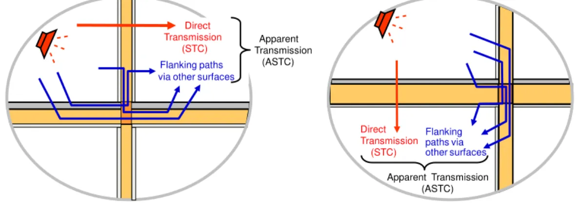
It is important to note that the ASTC rating is not interchangeable with the STC rating. The STC
rating only considers the sound transmitted through the common wall or floor between rooms.
The ASTC rating includes contributions from other transmission paths between the rooms
(referred to as flanking paths as shown in Figure 1) and is therefore a better metric of the sound
transmission that occupants in buildings will experience in practice. Since the ASTC rating
includes transmission paths other than the direct transmission path, it is typically lower in
numerical value than the STC rating of the common wall or floor.
Figure 1: Comparison between STC and ASTC
The 2015 NBCC allows for three methods of demonstrating compliance with the acoustic
requirements. The methods include post completion field testing, constructing buildings using
the prescribed acceptable solutions found in Part 9 of the NBCC and the prediction of the ASTC
rating using the prediction methods based on the standards, ISO 15712 [1] and ISO 10848 [2]
and described in detail in the National Research Council Canada Research Report RR-331
Guide to Calculating Airborne Sound Transmission in Buildings [3]. The Report RR-331 focuses
on the method of showing compliance by the prediction of the ASTC rating.
This report presents all of the laboratory measured data that is required to calculate the ASTC
rating of typical mid-rise wood constructions that include the CertainTeed gypsum board and
fiberglass insulation products which were evaluated for this study. The method of calculating
the ASTC rating is detailed and examples of typical mid-rise wood constructions using 15.9 mm
SilentFX® QuickCut gypsum board are presented. The examples include horizontal
transmission for side-by-side rooms and vertical transmission for one-above-the-other rooms.
Also presented in this report are the
Δ � ratings of linings for CLT
1constructions which can be
used to determine the ASTC ratings for CLT constructions which use the linings as explained in
the National Research Council Canada Research Report RR-335 Apparent Sound Insulation in
Cross-Laminated Timber Buildings [4].
Direct Transmission
(STC) Flanking paths via other surfaces
Apparent Transmission (ASTC) Direct Transmission (STC) Flanking paths via other surfaces Apparent Transmission (ASTC)
2. ASTC Examples Summary
Fifty five examples of the calculation of the ASTC rating of mid-rise wood constructions using
15.9 mm SilentFX® QuickCut Gypsum Board directly attached to single or triple staggered stud
walls are presented. The examples use the simplified method of the calculations as detailed in
the National Research Council Report RR-331 to calculate the ASTC rating of side-by-side
rooms and one-above-the-other rooms.
The examples include two different floor systems.
Floor system 1 is assembly FC-1 from Client Report A1-100035-02.1 available from
http://doi.org/10.4224/21274579
The floor details include:
One layer of 15.9 mm (5/8”) OSB directly attached to wood I-joists (type TJ1 110) 302 mm
(12”) deep spaced 406 mm (16”) on center. Rim board (45 mm (1-3/4”) thick and 302 mm
deep) installed at each end of the I-joists. The cavities between the I-joists filled with 150
mm R20 glass fiber insulation. Resilient channels installed perpendicular to the wood
I-joists and spaced 406 mm on center. Two layers of 12.7 mm
(1/2”) Type X gypsum board
installed with long axis perpendicular to the resilient channels. See report
A1-100035-02.1
for further details.
Floor system 2 has a UL/cUL fire resistance rating of one hour (UL/cUL Design M535). The
floor details are described in
UL Product Spec™ BXUV7 - Fire Resistance Ratings -
CAN/ULC-S101 Certified for Canada:
http://productspec.ul.com/document.php?id=BXUV.M535
The floor details include
One layer of 15 mm (19/32”) OSB directly attached to wood I-joists (type TJ1 110) 241.3
mm (9.5”) deep spaced 406 mm (16”) on center. Doubled-up rim board (32 mm (1-1/4”)
thick and 241.3 mm deep) installed at each end of the joists. The cavities between the
I-joists filled with 150 mm R20 glass fiber insulation. Resilient channels installed
perpendicular to the wood I-joists
and spaced 305 mm (12”) on center. Two courses of
resilient channel positioned back to back and oriented opposite at gypsum panel
butt-joints. Channel splices overlapped 102 mm (4”) beneath wood trusses. Base layer of 15.9
mm (5/8”) SilentFX® QuickCut Drywall 1200 mm (4’) wide, installed perpendicular to
resilient channels. Face layer of
2.7 mm (1/2”) thick x 1200 mm (4’) wide CertainTeed
Type C fire resistant drywall installed perpendicular to resilient channels. See reference
BXUV.M535
for further details.
Note that some of the floors shown in the example include bare subfloors. The examples are
shown with bare subfloors to demonstrate the minimum ASTC rating these constructions can
achieve. It is expected that in practice, floor finishes such as carpeting or tile will be installed
over the bare subfloor. The addition of floor finishes will in most cases achieve the same ASTC
ratings or increase the ASTC ratings shown in the examples.
The ASTC ratings for the constructions in the examples are summarized in the following tables.
The constructions are sorted by ASTC ratings. The constructions which achieve the highest
ASTC ratings are those which use 15.9 mm SilentFX® QuickCut Drywall in both rooms.
2.1 Summary - Side-By-Side Rooms - Non-loadbearing Common Wall
Example Number ASTC Rating Report Page Number Framing Shear WallGypsum Board Directly Attached to
the Wood Studs Floor System Floor Topping Common Wall Flanking Walls 2 50 16 Single Staggered Studs Triple Staggered Studs
No Mix of 15.9 mm SilentFX® QuickCut
Gypsum Board and 15.9 mm Type X 1 None
8 50 34 " " Yes " " " 10 50 38 " " Yes " " Two layers of 12 mm cementitious flooring underlayment 12 50 42 " " Yes " " 38 mm thick gypsum concrete on a 9 mm closed cell foam
45 50 28 " " No " 2 None 47 50 46 " " Yes " " " 4 51 20 " " No " 1 Two layers of 12 mm cementitious flooring underlayment 6 51 24 " " No " " 38 mm thick gypsum concrete on a 9 mm closed cell foam 7 53 32 " " Yes 15.9 mm SilentFX® QuickCut
Gypsum Board " None
13 53 48 " " Yes " " " 9 53 36 " " Yes " " Two layers of 12 mm cementitious flooring underlayment 11 53 40 " " Yes " " 38 mm thick gypsum concrete on a 9 mm closed cell foam
46 53 44 " " Yes " 2 None
Example Number ASTC Rating Report Page Number Framing Shear Wall
Gypsum Board Directly Attached to
the Wood Studs Floor System Floor Topping Common Wall Flanking Walls 14 54 50 Single Staggered Studs Triple Staggered Studs
Yes 15.9 mm SilentFX® QuickCut
Gypsum Board 1 None
3 54 18 " " No " " Two layers of 12 mm cementitious flooring underlayment 5 54 22 " " No " " 38 mm thick gypsum concrete on a 9 mm closed cell foam
2.2 Summary - Side-By-Side Rooms - Loadbearing Common Wall
Example Number ASTC Rating Report Page Number Framing Shear WallGypsum Board Directly Attached to
the Wood Studs Floor System Floor Topping Common Wall Flanking Walls 16 48 56 Triple Staggered Studs Single Staggered Studs
No Mix of 15.9 mm SilentFX® QuickCut
Gypsum Board and 15.9 mm Type X 1 None
22 48 74 " " Yes " " " 18 48 60 " " No " " Two layers of 12 mm cementitious flooring underlayment 24 48 78 " " Yes " " " 20 48 64 " " No " " 38 mm thick gypsum concrete on a 9 mm closed cell foam
26 48 82 " " Yes " " " 49 48 68 " " No " 2 None 51 48 86 " " Yes " " " 48 50 66 " " No 15.9 mm SilentFX® QuickCut Gypsum Board " " 50 50 84 " " Yes " " " 15 51 54 " " No " 1 " 21 51 72 " " Yes " " " 27 51 88 " " Yes " " " 28 51 90 " " Yes " " "
Example Number ASTC Rating Report Page Number Framing Shear Wall
Gypsum Board Directly Attached to
the Wood Studs Floor System Floor Topping Common Wall Flanking Walls 17 51 58 Triple Staggered Studs Single Staggered Studs No 15.9 mm SilentFX® QuickCut Gypsum Board 1 Two layers of 12 mm cementitious flooring underlayment 23 51 76 " " Yes " " " 19 51 62 " " No " " 38 mm thick gypsum concrete on a 9 mm closed cell foam
2.3 Summary - Rooms One-above-the-Other
Example Number ASTC Rating Report Page Number Framing Shear WallGypsum Board Directly Attached to
the Wood Studs Floor System Floor Topping Floor Walls 53 49 108 I-Joists Single and Triple Staggered Studs
No Mix of 15.9 mm SilentFX® QuickCut
Gypsum Board and 15.9 mm Type X 2 None
55 49 126 " " Yes " " "
52 50 106 " " No 15.9 mm SilentFX® QuickCut
Gypsum Board " "
54 50 124 " " Yes " " "
30 52 96 " " No Mix of 15.9 mm SilentFX® QuickCut
Gypsum Board and 15.9 mm Type X 1 "
36 52 114 " " Yes " " " 29 52 94 " " No 15.9 mm SilentFX® QuickCut Gypsum Board " " 35 52 112 " " Yes " " " 41 52 128 " " Yes " " " 42 52 130 " " Yes " " "
32 55 100 " " No Mix of 15.9 mm SilentFX® QuickCut
Gypsum Board and 15.9 mm Type X "
Two layers of 12 mm cementitious flooring underlayment 38 55 118 " " Yes " " " 31 56 98 " " No 15.9 mm SilentFX® QuickCut Gypsum Board " " 37 56 116 " " Yes " " "
Example Number ASTC Rating Report Page Number Framing Shear Wall
Gypsum Board Directly Attached to
the Wood Studs Floor System Floor Topping Floor Walls 34 61 104 I-Joists Single and Triple Staggered Studs
No Mix of 15.9 mm SilentFX® QuickCut
Gypsum Board and 15.9 mm Type X 1
38 mm thick gypsum concrete on a 9 mm closed cell foam
40 61 122 " " Yes " " "
33 63 102 " " No 15.9 mm SilentFX® QuickCut
Gypsum Board " "
3. Standard Scenarios for the ASTC Examples
For the purposes of this report, the ASTC ratings of mid-rise wood constructions are calculated
using the Standard Scenarios presented in the National Research Council Canada Research
Report RR-331 for side-by-side and one-above-the-other rooms. The Standard Scenario rooms
are shown in Figure 2 and Figure 3.
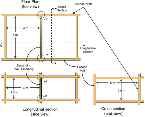
Figure 2: Standard Scenario from the NRC Research Report RR-331
for “horizontal
room pair” case where the rooms are side-by side with a separating wall
assembly between the rooms.
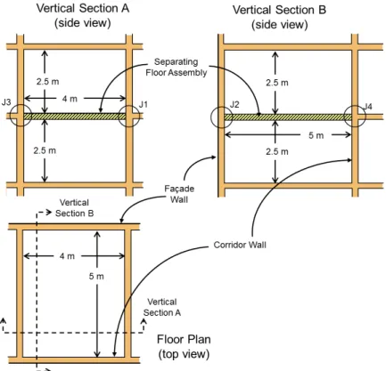
Figure 3: Standard Scenario from the NRC Research Report RR-331
for “vertical
room pair” case where one of the pair of rooms is above the other with a
floor/ceiling assembly between the two rooms.
The pertinent dimensions and junction details of the Standard Scenario rooms are:
For horizontal room pairs (rooms are side-by-side) the separating wall is 2.5 m high by
5 m wide, the flanking floors and ceilings are 4 m by 5 m and the flanking walls are 2.5 m
by 4 m.
For vertical room pairs (one room is above the other) the separating floor/ceiling is 4 m by
5 m and the flanking walls in both rooms are 2.5 m high.
In general, it is assumed that the junctions at one side of the room (at the separating wall
if rooms are side-by-side) are cross junctions, while one or both of the other two junctions
are T-junctions. This enables the examples to illustrate the typical differences between
the two common junction cases.
For a horizontal room pair, the separating wall has T-junctions with the flanking walls at
both the façade and corridor sides and cross junctions at the floor and ceiling.
For a vertical room pair, the façade wall has a T-junction with the separating floor, but the
opposing corridor wall has a cross junction, as do the other two walls.
4. ASTC Examples
Examples of the calculation of the ASTC ratings of mid-rise wood constructions are shown in
the following sections. The examples use the simplified method of the calculations as detailed
in the National Research Council Report RR-331.
4.1 Side-by-Side Rooms: Non-Load Bearing Single Staggered Stud Separating
Wall Assembly
Example Number ASTC Rating Construction Wallboard Room 1 WallboardRoom 2 Floor System
Floor Topping Room 1 Floor Topping Room 2 1 54 One layer of 15.9 mm SilentFX® QuickCut Gypsum Board One layer of 15.9 mm SilentFX® QuickCut Gypsum Board 1 None None 2 50 " One layer of 15.9 mm CertainTeed Type X gypsum board " None " 3 54 " One layer of 15.9 mm SilentFX® QuickCut Gypsum Board " Two layers of 12 mm cementitious flooring underlayment " 4 51 " One layer of 15.9 mm CertainTeed Type X gypsum board " " " 5 54 " One layer of 15.9 mm SilentFX® QuickCut Gypsum Board " 38 mm thick gypsum concrete on a 9 mm closed cell foam " 6 51 " One layer of 15.9 mm CertainTeed Type X gypsum board " " " 44 54 " One layer of 15.9 mm SilentFX® QuickCut Gypsum Board 2 None None 45 50 " One layer of 15.9 mm CertainTeed Type X gypsum board " " "
Example 1: Rooms side-by-side - Non-loadbearing Separating Wall Simplified Method.
Common single staggered wood stud wall.
All other walls are triple staggered wood stud walls.
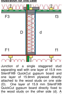
One layer of 15.9 mm (5/8”) CertainTeed SilentFX® QuickCut gypsum board directly fixed to the wood studs of all walls. One layer of 15 mm OSB on the floors.
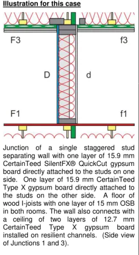
Illustration for this case
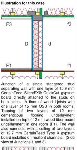
Junction of a single staggered stud separating wall with one layer of 15.9 mm CertainTeed SilentFX® QuickCut gypsum board directly attached to the studs on both sides. A floor of wood I-joists with one layer of 15 mm OSB in both rooms. The wall also connects with a ceiling of two layers of 12.7 mm CertainTeed Type X gypsum board installed on resilient channels.
(Side view of Junctions 1 and 3).
Junction of a single staggered stud separating wall with side walls of triple staggered studs. One layer of 15.9 mm SilentFX® QuickCut gypsum board directly attached to the wood studs in both rooms. (Plan view of Junction 2 or 4).
Separating wall assembly (non-loadbearing) with:
Staggered 38 mm x 89 mm (2x4) wood studs spaced 400 mm on center. Double headers and a single footer 38 mm x 140 mm (2x6). One layer of 15.9 mm SilentFX® QuickCut gypsum board directly
attached to each side of the wood studs.
One layer of 89 mm thick CertainTeed R12 Sustainable Insulation® in the wall cavity.
Junction 1: Bottom Junction (separating wall / floor) with: Joists oriented parallel to the separating wall assembly.
Wood I-joists 302 mm deep spaced 400 mm on center. Rim boards (45 mm thick and 302 mm deep) installed at each end of the I-joists. Subfloor of one layer of 15 mm OSB directly attached to I-joists. One layer of 152 mm thick CertainTeed R20 Sustainable Insulation®
in the floor cavity.
Junction 2 or 4: Each Side (separating wall /abutting side wall) with: Triple staggered 38 mm x 89 mm wood studs spaced 400 mm on
center. Double headers and a single footer 38 mm x 140 mm. One layer of 15.9 mm SilentFX® QuickCut gypsum board directly
attached to each side of the wood studs.
One layer of 89 mm thick CertainTeed R12 Sustainable Insulation® in the wall cavity.
Junction 3: Top Junction (separating wall / ceiling) with: Joists oriented parallel to the separating wall assembly.
Wood I-joists 302 mm deep spaced 400 mm on center. Rim boards (45 mm thick and 302 mm deep) installed at each end of the I-joists. Resilient channels installed perpendicular to wood I-joists and
spaced 400 mm on center.
Two layers of 12.7 mm CertainTeed Type X gypsum board installed on the resilient channels on the ceiling.
One layer of 152 mm thick CertainTeed R20 Sustainable Insulation® in the ceiling cavity.
Room Parameters
See Figure 2 of this report or Figure 1.3 of the National Research Council Report RR-331.
The separating wall is 2.5 m high by 5 m wide. The flanking walls 2.5 m high by 4 m wide. The floor / ceilings are 4 m by 5 m.
Reference Value
Direct STC Rating of Path Dd
Report A1-007750.2 Appendix B 54
Junction 1 - Seperating wall and the floor assembly Flanking Path Ff_1
Report A1-007750.2 Appendix B,C and D 66
Normalization Correction RR-331 Eq. 1.5 3.98
RR-331 Eq. 1.5 70
Flanking Path Fd_1
Report A1-007750.2 Appendix B,C and D 73
Normalization Correction RR-331 Eq. 1.5 3.98
RR-331 Eq. 1.5 77
Flanking Path Df_1
Report A1-007750.2 Appendix B,C and D 73
Normalization Correction RR-331 Eq. 1.5 3.98
RR-331 Eq. 1.5 77
Flanking STC for Junction 1 69
Junction 2 - Separating wall and the flanking wall assemblies Flanking Path Ff_2
Report A1-007750.2 Appendix B,C and D 69
Normalization Correction RR-331 Eq. 1.5 6.99
RR-331 Eq. 1.5 76
Flanking Path Fd_2
Report A1-007750.2 Appendix B,C and D 72
Normalization Correction RR-331 Eq. 1.5 6.99
RR-331 Eq. 1.5 79
Flanking Path Df_2
Report A1-007750.2 Appendix B,C and D 72
Normalization Correction RR-331 Eq. 1.5 6.99
RR-331 Eq. 1.5 79
Flanking STC for Junction 2 73
Junction 3 -Seperating wall and the ceiling assembly Flanking Path Ff_3
Report A1-007750.2 Appendix B,C and D 73
Normalization Correction RR-331 Eq. 1.5 3.98
RR-331 Eq. 1.5 77
Flanking Path Fd_3
Report A1-007750.2 Appendix B,C and D 71
Normalization Correction RR-331 Eq. 1.5 3.98
RR-331 Eq. 1.5 75
Flanking Path Df_3
Report A1-007750.2 Appendix B,C and D 71
Normalization Correction RR-331 Eq. 1.5 3.98
RR-331 Eq. 1.5 75
Flanking STC for Junction 3 71
Junction 4 - Separating wall and the flanking wall assemblies
Flanking STC for Junction 4 - Same as Junction 2 73
54 ASTC due to Direct plus Flanking Transmission RR-331 Equation 1.4
� � � � � � � � � � � � � � � � � � � Example 1
Example 2: Rooms side-by-side - Non-loadbearing Separating Wall Simplified Method.
Common single staggered wood stud wall.
All other walls are triple staggered wood stud walls.
One layer of 15.9 mm (5/8”) CertainTeed SilentFX® QuickCut gypsum board fixed to the wood studs in one room.
One layer of 15.9 mm (5/8”) CertainTeed Type X fixed to the wood studs in the other room.
One layer of 15.9 mm OSB on the floors.
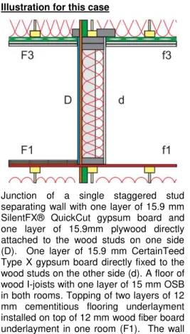
Illustration for this case
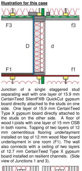
Junction of a single staggered stud separating wall with one layer of 15.9 mm CertainTeed SilentFX® QuickCut gypsum board directly attached to the studs on one side. One layer of 15.9 mm CertainTeed Type X gypsum board directly attached to the studs on the other side. A floor of wood I-joists with one layer of 15 mm OSB in both rooms. The wall also connects with a ceiling of two layers of 12.7 mm CertainTeed Type X gypsum board installed on resilient channels. (Side view of Junctions 1 and 3).
Junction of a single staggered stud separating wall with side walls of triple staggered studs. One layer of 15.9 mm SilentFX® QuickCut gypsum board directly attached to the wood studs in one room. One layer of 15.9 mm CertainTeed Type X gypsum board directly attached to the wood studs in the other room. (Plan view of Junction 2 or 4).
Separating wall assembly (non-loadbearing) with:
Staggered 38 mm x 89 mm (2x4) wood studs spaced 400 mm on center. Double headers and a single footer 38 mm x 140 mm (2x6). One layer of 15.9 mm SilentFX® QuickCut gypsum board directly
attached to one side of the wood studs and one layer of 15.9 mm CertainTeed Type X gypsum board directly attached to the other side of the wood studs.
One layer of 89 mm thick CertainTeed R12 Sustainable Insulation® in the wall cavity.
Junction 1: Bottom Junction (separating wall / floor) with: Joists oriented parallel to the separating wall assembly.
Wood I-joists 302 mm deep spaced 400 mm on center. Rim boards (45 mm thick and 302 mm deep) installed at each end of the I-joists. Subfloor of one layer of 15 mm OSB directly attached to I-joists. One layer of 152 mm thick CertainTeed R20 Sustainable Insulation®
in the floor cavity.
Junction 2 or 4: Each Side (separating wall /abutting side wall) with: Tipple staggered 38 mm x 89 mm wood studs spaced 400 mm on
center. Double headers and a single footer 38 mm x 140 mm. One layer of 15.9 mm SilentFX® QuickCut gypsum board directly
attached to the wood studs in one room (F2 and F4).
One layer of 15.9 mm CertainTeed Type X gypsum board directly attached to the wood studs in the other room (f2 and f4).
One layer of 89 mm thick CertainTeed R12 Sustainable Insulation® in the wall cavities.
Junction 3: Top Junction (separating wall / ceiling) with: Joists oriented parallel to the separating wall assembly.
Wood I-joists 302 mm deep spaced 400 mm on center. Rim boards (45 mm thick and 302 mm deep) installed at each end of the I-joists. Resilient channels installed perpendicular to wood I-joists and
spaced 400 mm on center.
Two layers of 12.7 mm CertainTeed Type X gypsum board installed on the resilient channels on the ceiling.
One layer of 152 mm thick CertainTeed R20 Sustainable Insulation® in the ceiling cavity.
Room Parameters
See Figure 2 of this report or Figure 1.3 of the National Research Council Report RR-331.
The separating wall is 2.5 m high by 5 m wide. The flanking walls 2.5 m high by 4 m wide. The floor / ceilings are 4 m by 5 m.
Reference Value
Direct STC Rating of Path Dd
Report A1-007750.2 Appendix B 51
Junction 1 - Seperating wall and the floor assembly Flanking Path Ff_1
Report A1-007750.2 Appendix B,C and D 66
Normalization Correction RR-331 Eq. 1.5 3.98
RR-331 Eq. 1.5 70
Flanking Path Fd_1
Report A1-007750.2 Appendix B,C and D 64
Normalization Correction RR-331 Eq. 1.5 3.98
RR-331 Eq. 1.5 68
Flanking Path Df_1
Report A1-007750.2 Appendix B,C and D 66
Normalization Correction RR-331 Eq. 1.5 3.98
RR-331 Eq. 1.5 70
Flanking STC for Junction 1 64
Junction 2 - Separating wall and the flanking wall assemblies Flanking Path Ff_2
Report A1-007750.2 Appendix B,C and D 66
Normalization Correction RR-331 Eq. 1.5 6.99
RR-331 Eq. 1.5 73
Flanking Path Fd_2
Report A1-007750.2 Appendix B,C and D 67
Normalization Correction RR-331 Eq. 1.5 6.99
RR-331 Eq. 1.5 74
Flanking Path Df_2
Report A1-007750.2 Appendix B,C and D 68
Normalization Correction RR-331 Eq. 1.5 6.99
RR-331 Eq. 1.5 75
Flanking STC for Junction 2 69
Junction 3 -Seperating wall and the ceiling assembly Flanking Path Ff_3
Report A1-007750.2 Appendix B,C and D 66
Normalization Correction RR-331 Eq. 1.5 3.98
RR-331 Eq. 1.5 70
Flanking Path Fd_3
Report A1-007750.2 Appendix B,C and D 63
Normalization Correction RR-331 Eq. 1.5 3.98
RR-331 Eq. 1.5 67
Flanking Path Df_3
Report A1-007750.2 Appendix B,C and D 65
Normalization Correction RR-331 Eq. 1.5 3.98
RR-331 Eq. 1.5 69
Flanking STC for Junction 3 64
Junction 4 - Separating wall and the flanking wall assemblies
Flanking STC for Junction 4 - Same as Junction 2 69
50 ASTC due to Direct plus Flanking Transmission RR-331 Equation 1.4
� � � � � � � � � � � � � � � � � � � Example 2
Example 3: Rooms side-by-side - Non-loadbearing Separating Wall Simplified Method.
Common single staggered wood stud wall.
All other walls are triple staggered wood stud walls.
One layer of 15.9 mm (5/8”) CertainTeed SilentFX® QuickCut gypsum board directly fixed to the wood studs of all walls. Topping of cementitious flooring in one room.
Illustration for this case
Junction of a single staggered stud separating wall with one layer of 15.9 mm CertainTeed SilentFX® QuickCut gypsum board directly attached to the studs on both sides. A floor of wood I-joists with one layer of 15 mm OSB in both rooms. Topping of two layers of 12 mm cementitious flooring underlayment installed on top of 12 mm wood fiber board underlayment in one room (F1). The wall also connects with a ceiling of two layers of 12.7 mm CertainTeed Type X gypsum board installed on resilient channels. (Side view of Junctions 1 and 3).
Junction of a single staggered stud separating wall with side walls of triple staggered studs. One layer of 15.9 mm SilentFX® QuickCut gypsum board directly attached to the wood studs in both rooms. (Plan view of Junction 2 or 4).
Separating wall assembly (non-loadbearing) with:
Staggered 38 mm x 89 mm (2x4) wood studs spaced 400 mm on center. Double headers and a single footer 38 mm x 140 mm (2x6). One layer of 15.9 mm SilentFX® QuickCut gypsum board directly
attached to each side of the wood studs.
One layer of 89 mm thick CertainTeed R12 Sustainable Insulation® in the wall cavity.
Junction 1: Bottom Junction (separating wall / floor) with: Joists oriented parallel to the separating wall assembly.
Wood I-joists 302 mm deep spaced 400 mm on center. Rim boards (45 mm thick and 302 mm deep) installed at each end of the I-joists. Subfloor of one layer of 15 mm OSB directly attached to I-joists. One layer of 152 mm thick CertainTeed R20 Sustainable Insulation®
in the floor cavity.
Topping of two layers of 12 mm cementitious flooring underlayment installed on top of 12 mm wood fiber board underlayment in one room (F1).
Junction 2 or 4: Each Side (separating wall /abutting side wall) with: Triple staggered 38 mm x 89 mm wood studs spaced 400 mm on
center. Double headers and a single footer 38 mm x 140 mm. One layer of 15.9 mm SilentFX® QuickCut gypsum board directly
attached to each side of the wood studs.
One layer of 89 mm thick CertainTeed R12 Sustainable Insulation® in the wall cavity.
Junction 3: Top Junction (separating wall / ceiling) with: Joists oriented parallel to the separating wall assembly.
Wood I-joists 302 mm deep spaced 400 mm on center. Rim boards (45 mm thick and 302 mm deep) installed at each end of the I-joists. Resilient channels installed perpendicular to wood I-joists and
spaced 400 mm on center.
Two layers of 12.7 mm CertainTeed Type X gypsum board installed on the resilient channels on the ceiling.
One layer of 152 mm thick CertainTeed R20 Sustainable Insulation® in the ceiling cavity.
Room Parameters
See Figure 2 of this report or Figure 1.3 of the National Research Council Report RR-331.
The separating wall is 2.5 m high by 5 m wide. The flanking walls 2.5 m high by 4 m wide. The floor / ceilings are 4 m by 5 m.
Reference Value
Direct STC Rating of Path Dd
Report A1-007750.2 Appendix B 54
Junction 1 - Seperating wall and the floor assembly Flanking Path Ff_1
Report A1-007750.2 Appendix B,C and D 68
Normalization Correction RR-331 Eq. 1.5 3.98
RR-331 Eq. 1.5 72
Flanking Path Fd_1
Report A1-007750.2 Appendix B,C and D 75
Normalization Correction RR-331 Eq. 1.5 3.98
RR-331 Eq. 1.5 79
Flanking Path Df_1
Report A1-007750.2 Appendix B,C and D 73
Normalization Correction RR-331 Eq. 1.5 3.98
RR-331 Eq. 1.5 77
Flanking STC for Junction 1 70
Junction 2 - Separating wall and the flanking wall assemblies Flanking Path Ff_2
Report A1-007750.2 Appendix B,C and D 69
Normalization Correction RR-331 Eq. 1.5 6.99
RR-331 Eq. 1.5 76
Flanking Path Fd_2
Report A1-007750.2 Appendix B,C and D 72
Normalization Correction RR-331 Eq. 1.5 6.99
RR-331 Eq. 1.5 79
Flanking Path Df_2
Report A1-007750.2 Appendix B,C and D 72
Normalization Correction RR-331 Eq. 1.5 6.99
RR-331 Eq. 1.5 79
Flanking STC for Junction 2 73
Junction 3 -Seperating wall and the ceiling assembly Flanking Path Ff_3
Report A1-007750.2 Appendix B,C and D 73
Normalization Correction RR-331 Eq. 1.5 3.98
RR-331 Eq. 1.5 77
Flanking Path Fd_3
Report A1-007750.2 Appendix B,C and D 71
Normalization Correction RR-331 Eq. 1.5 3.98
RR-331 Eq. 1.5 75
Flanking Path Df_3
Report A1-007750.2 Appendix B,C and D 71
Normalization Correction RR-331 Eq. 1.5 3.98
RR-331 Eq. 1.5 75
Flanking STC for Junction 3 71
Junction 4 - Separating wall and the flanking wall assemblies
Flanking STC for Junction 4 - Same as Junction 2 73
54 ASTC due to Direct plus Flanking Transmission RR-331 Equation 1.4
� � � � � � � � � � � � � � � � � � � Example 3
Example 4: Rooms side-by-side - Non-loadbearing Separating Wall Simplified Method.
Common single staggered wood stud wall.
All other walls are triple staggered wood stud walls.
One layer of 15.9 mm (5/8”) CertainTeed SilentFX® QuickCut gypsum board fixed to the wood studs in one room.
One layer of 15.9 mm (5/8”) CertainTeed Type X fixed to the wood studs in the other room.
Topping of cementitious flooring in one room.
Illustration for this case
Junction of a single staggered stud separating wall with one layer of 15.9 mm CertainTeed SilentFX® QuickCut gypsum board directly attached to the studs on one side. One layer of 15.9 mm CertainTeed Type X gypsum board directly attached to the studs on the other side. A floor of wood I-joists with one layer of 15 mm OSB in both rooms. Topping of two layers of 12 mm cementitious flooring underlayment installed on top of 12 mm wood fiber board underlayment in one room (F1). The wall also connects with a ceiling of two layers of 12.7 mm CertainTeed Type X gypsum board installed on resilient channels. (Side view of Junctions 1 and 3).
Junction of single staggered stud separating wall with side walls of triple staggered studs. One layer of 15.9 mm SilentFX® QuickCut gypsum board directly attached to the wood studs in one room. CertainTeed Type X gypsum board directly attached to the wood studs in the other room. (Plan view of Junction 2 or 4). Separating wall assembly (non-loadbearing) with:
Staggered 38 mm x 89 mm (2x4) wood studs spaced 400 mm on center. Double headers and a single footer 38 mm x 140 mm (2x6). One layer of 15.9 mm SilentFX® QuickCut gypsum board directly
attached to one side of the wood studs and one layer of 15.9 mm CertainTeed Type X gypsum board directly attached to the other side of the wood studs.
One layer of 89 mm thick CertainTeed R12 Sustainable Insulation® in the wall cavity.
Junction 1: Bottom Junction (separating wall / floor) with: Joists oriented parallel to the separating wall assembly.
Wood I-joists 302 mm deep spaced 400 mm on center. Rim boards (45 mm thick and 302 mm deep) installed at each end of the I-joists. Subfloor of one layer of 15 mm OSB directly attached to I-joists. One layer of 152 mm thick CertainTeed R20 Sustainable Insulation®
in the floor cavity.
Topping of two layers of 12 mm cementitious flooring underlayment installed on top of 12 mm wood fiber board underlayment in one room (F1).
Junction 2 or 4: Each Side (separating wall /abutting side wall) with: Tipple staggered 38 mm x 89 mm wood studs spaced 400 mm on
center. Double headers and a single footer 38 mm x 140 mm. One layer of 15.9 mm SilentFX® QuickCut gypsum board directly
attached to the wood studs in one room (F2 and F4).
One layer of 15.9 mm CertainTeed Type X gypsum board directly attached to the wood studs in the other room (f2 and f4).
One layer of 89 mm thick CertainTeed R12 Sustainable Insulation® in the wall cavities.
Junction 3: Top Junction (separating wall / ceiling) with: Joists oriented parallel to the separating wall assembly.
Wood I-joists 302 mm deep spaced 400 mm on center. Rim boards (45 mm thick and 302 mm deep) installed at each end of the I-joists. Resilient channels installed perpendicular to wood I-joists and
spaced 400 mm on center.
Two layers of 12.7 mm CertainTeed Type X gypsum board installed on the resilient channels on the ceiling.
One layer of 152 mm thick CertainTeed R20 Sustainable Insulation® in the ceiling cavity.
Room Parameters
See Figure 2 of this report or Figure 1.3 of the National Research Council Report RR-331.
The separating wall is 2.5 m high by 5 m wide. The flanking walls 2.5 m high by 4 m wide. The floor / ceilings are 4 m by 5 m.
Reference Value
Direct STC Rating of Path Dd
Report A1-007750.2 Appendix B 51
Junction 1 - Seperating wall and the floor assembly Flanking Path Ff_1
Report A1-007750.2 Appendix B,C and D 68
Normalization Correction RR-331 Eq. 1.5 3.98
RR-331 Eq. 1.5 72
Flanking Path Fd_1
Report A1-007750.2 Appendix B,C and D 66
Normalization Correction RR-331 Eq. 1.5 3.98
RR-331 Eq. 1.5 70
Flanking Path Df_1
Report A1-007750.2 Appendix B,C and D 66
Normalization Correction RR-331 Eq. 1.5 3.98
RR-331 Eq. 1.5 70
Flanking STC for Junction 1 66
Junction 2 - Separating wall and the flanking wall assemblies Flanking Path Ff_2
Report A1-007750.2 Appendix B,C and D 66
Normalization Correction RR-331 Eq. 1.5 6.99
RR-331 Eq. 1.5 73
Flanking Path Fd_2
Report A1-007750.2 Appendix B,C and D 67
Normalization Correction RR-331 Eq. 1.5 6.99
RR-331 Eq. 1.5 74
Flanking Path Df_2
Report A1-007750.2 Appendix B,C and D 68
Normalization Correction RR-331 Eq. 1.5 6.99
RR-331 Eq. 1.5 75
Flanking STC for Junction 2 69
Junction 3 -Seperating wall and the ceiling assembly Flanking Path Ff_3
Report A1-007750.2 Appendix B,C and D 66
Normalization Correction RR-331 Eq. 1.5 3.98
RR-331 Eq. 1.5 70
Flanking Path Fd_3
Report A1-007750.2 Appendix B,C and D 63
Normalization Correction RR-331 Eq. 1.5 3.98
RR-331 Eq. 1.5 67
Flanking Path Df_3
Report A1-007750.2 Appendix B,C and D 65
Normalization Correction RR-331 Eq. 1.5 3.98
RR-331 Eq. 1.5 69
Flanking STC for Junction 3 64
Junction 4 - Separating wall and the flanking wall assemblies
Flanking STC for Junction 4 - Same as Junction 2 69
51 ASTC due to Direct plus Flanking Transmission RR-331 Equation 1.4
� � � � � � � � � � � � � � � � � � � Example 4
Example 5: Rooms side-by-side - Non-loadbearing Separating Wall Simplified Method.
Common single staggered wood stud wall.
All other walls are triple staggered wood stud walls.
One layer of 15.9 mm (5/8”) CertainTeed SilentFX® QuickCut gypsum board directly fixed to the wood studs of all walls. Topping of 38 mm thick gypsum concrete in one room.
Illustration for this case
Junction of a single staggered stud separating wall with one layer of 15.9 mm CertainTeed SilentFX® QuickCut gypsum board directly attached to the studs on both sides. A floor of wood I-joists with one layer of 15 mm OSB in both rooms. Topping of 38 mm thick gypsum concrete on a 9 mm closed cell foam interlayer in one room (F1). The wall also connects with a ceiling of two layers of 12.7 mm CertainTeed Type X gypsum board installed on resilient channels. (Side view of Junctions 1 and 3).
Junction of a single staggered stud separating wall with side walls of triple staggered studs. One layer of 15.9 mm SilentFX® QuickCut gypsum board directly attached to the wood studs in both rooms. (Plan view of Junction 2 or 4).
Separating wall assembly (non-loadbearing) with:
Staggered 38 mm x 89 mm (2x4) wood studs spaced 400 mm on center. Double headers and a single footer 38 mm x 140 mm (2x6). One layer of 15.9 mm SilentFX® QuickCut gypsum board directly
attached to each side of the wood studs.
One layer of 89 mm thick CertainTeed R12 Sustainable Insulation® in the wall cavity.
Junction 1: Bottom Junction (separating wall / floor) with: Joists oriented parallel to the separating wall assembly.
Wood I-joists 302 mm deep spaced 400 mm on center. Rim boards (45 mm thick and 302 mm deep) installed at each end of the I-joists. Subfloor of one layer of 15 mm OSB directly attached to I-joists. One layer of 152 mm thick CertainTeed R20 Sustainable Insulation®
in the floor cavity.
Topping of 38 mm thick gypsum concrete on a 9 mm closed cell foam interlayer in one room (F1).
Junction 2 or 4: Each Side (separating wall /abutting side wall) with: Triple staggered 38 mm x 89 mm wood studs spaced 400 mm on
center. Double headers and a single footer 38 mm x 140 mm. One layer of 15.9 mm SilentFX® QuickCut gypsum board directly
attached to each side of the wood studs.
One layer of 89 mm thick CertainTeed R12 Sustainable Insulation® in the wall cavity.
Junction 3: Top Junction (separating wall / ceiling) with: Joists oriented parallel to the separating wall assembly.
Wood I-joists 302 mm deep spaced 400 mm on center. Rim boards (45 mm thick and 302 mm deep) installed at each end of the I-joists. Resilient channels installed perpendicular to wood I-joists and
spaced 400 mm on center.
Two layers of 12.7 mm CertainTeed Type X gypsum board installed on the resilient channels on the ceiling.
One layer of 152 mm thick CertainTeed R20 Sustainable Insulation® in the ceiling cavity.
Room Parameters
See Figure 2 of this report or Figure 1.3 of the National Research Council Report RR-331.
The separating wall is 2.5 m high by 5 m wide. The flanking walls 2.5 m high by 4 m wide. The floor / ceilings are 4 m by 5 m.
Reference Value
Direct STC Rating of Path Dd
Report A1-007750.2 Appendix B 54
Junction 1 - Seperating wall and the floor assembly Flanking Path Ff_1
Report A1-007750.2 Appendix B,C and D 73
Normalization Correction RR-331 Eq. 1.5 3.98
RR-331 Eq. 1.5 77
Flanking Path Fd_1
Report A1-007750.2 Appendix B,C and D 81
Normalization Correction RR-331 Eq. 1.5 3.98
RR-331 Eq. 1.5 85
Flanking Path Df_1
Report A1-007750.2 Appendix B,C and D 73
Normalization Correction RR-331 Eq. 1.5 3.98
RR-331 Eq. 1.5 77
Flanking STC for Junction 1 74
Junction 2 - Separating wall and the flanking wall assemblies Flanking Path Ff_2
Report A1-007750.2 Appendix B,C and D 69
Normalization Correction RR-331 Eq. 1.5 6.99
RR-331 Eq. 1.5 76
Flanking Path Fd_2
Report A1-007750.2 Appendix B,C and D 72
Normalization Correction RR-331 Eq. 1.5 6.99
RR-331 Eq. 1.5 79
Flanking Path Df_2
Report A1-007750.2 Appendix B,C and D 72
Normalization Correction RR-331 Eq. 1.5 6.99
RR-331 Eq. 1.5 79
Flanking STC for Junction 2 73
Junction 3 -Seperating wall and the ceiling assembly Flanking Path Ff_3
Report A1-007750.2 Appendix B,C and D 73
Normalization Correction RR-331 Eq. 1.5 3.98
RR-331 Eq. 1.5 77
Flanking Path Fd_3
Report A1-007750.2 Appendix B,C and D 71
Normalization Correction RR-331 Eq. 1.5 3.98
RR-331 Eq. 1.5 75
Flanking Path Df_3
Report A1-007750.2 Appendix B,C and D 71
Normalization Correction RR-331 Eq. 1.5 3.98
RR-331 Eq. 1.5 75
Flanking STC for Junction 3 71
Junction 4 - Separating wall and the flanking wall assemblies
Flanking STC for Junction 4 - Same as Junction 2 73
54 ASTC due to Direct plus Flanking Transmission RR-331 Equation 1.4
� � � � � � � � � � � � � � � � � � � Example 5
Example 6: Rooms side-by-side - Non-loadbearing Separating Wall Simplified Method.
Common single staggered wood stud wall.
All other walls are triple staggered wood stud walls.
One layer of 15.9 mm (5/8”) CertainTeed SilentFX® QuickCut gypsum board fixed to the wood studs in one room.
One layer of 15.9 mm (5/8”) CertainTeed Type X fixed to the wood studs in the other room.
Topping of 38 mm thick gypsum concrete in one room.
Illustration for this case
Junction of a single staggered stud separating wall with one layer of 15.9 mm CertainTeed SilentFX® QuickCut gypsum board directly attached to the studs on one side. One layer of 15.9 mm CertainTeed Type X gypsum board directly attached to the studs on the other side. A floor of wood I-joists with one layer of 15 mm OSB in both rooms. Topping of 38 mm thick gypsum concrete on a 9 mm closed cell foam interlayer in one room (F1). The wall also connects with a ceiling of two layers of 12.7 mm CertainTeed Type X gypsum board installed on resilient channels. (Side view of Junctions 1 and 3).
Junction of a single staggered stud separating wall with side walls of triple staggered studs. One layer of 15.9 mm SilentFX® QuickCut gypsum board directly attached to the wood studs in one room. One layer of 15.9 mm CertainTeed Type X gypsum board directly attached to the wood studs in the other room. (Plan view of Junction 2 or 4).
Separating wall assembly (non-loadbearing) with:
Staggered 38 mm x 89 mm (2x4) wood studs spaced 400 mm on center. Double headers and a single footer 38 mm x 140 mm (2x6). One layer of 15.9 mm SilentFX® QuickCut gypsum board directly
attached to one side of the wood studs and one layer of 15.9 mm CertainTeed Type X gypsum board directly attached to the other side of the wood studs.
One layer of 89 mm thick CertainTeed R12 Sustainable Insulation® in the wall cavity.
Junction 1: Bottom Junction (separating wall / floor) with: Joists oriented parallel to the separating wall assembly.
Wood I-joists 302 mm deep spaced 400 mm on center. Rim boards (45 mm thick and 302 mm deep) installed at each end of the I-joists. Subfloor of one layer of 15 mm OSB directly attached to I-joists. One layer of 152 mm thick CertainTeed R20 Sustainable Insulation®
in the floor cavity.
Topping of 38 mm thick gypsum concrete on a 9 mm closed cell foam interlayer in one room (F1).
Junction 2 or 4: Each Side (separating wall /abutting side wall) with: Tipple staggered 38 mm x 89 mm wood studs spaced 400 mm on
center. Double headers and a single footer 38 mm x 140 mm. One layer of 15.9 mm SilentFX® QuickCut gypsum board directly
attached to the wood studs in one room (F2 and F4).
One layer of 15.9 mm CertainTeed Type X gypsum board directly attached to the wood studs in the other room (f2 and f4).
One layer of 89 mm thick CertainTeed R12 Sustainable Insulation® in the wall cavities.
Junction 3: Top Junction (separating wall / ceiling) with: Joists oriented parallel to the separating wall assembly.
Wood I-joists 302 mm deep spaced 400 mm on center. Rim boards (45 mm thick and 302 mm deep) installed at each end of the I-joists. Resilient channels installed perpendicular to wood I-joists and
spaced 400 mm on center.
Two layers of 12.7 mm CertainTeed Type X gypsum board installed on the resilient channels on the ceiling.
One layer of 152 mm thick CertainTeed R20 Sustainable Insulation® in the ceiling cavity.
Room Parameters
See Figure 2 of this report or Figure 1.3 of the National Research Council Report RR-331.
The separating wall is 2.5 m high by 5 m wide. The flanking walls 2.5 m high by 4 m wide. The floor / ceilings are 4 m by 5 m.
Reference Value
Direct STC Rating of Path Dd
Report A1-007750.2 Appendix B 51
Junction 1 - Seperating wall and the floor assembly Flanking Path Ff_1
Report A1-007750.2 Appendix B,C and D 73
Normalization Correction RR-331 Eq. 1.5 3.98
RR-331 Eq. 1.5 77
Flanking Path Fd_1
Report A1-007750.2 Appendix B,C and D 71
Normalization Correction RR-331 Eq. 1.5 3.98
RR-331 Eq. 1.5 75
Flanking Path Df_1
Report A1-007750.2 Appendix B,C and D 66
Normalization Correction RR-331 Eq. 1.5 3.98
RR-331 Eq. 1.5 70
Flanking STC for Junction 1 68
Junction 2 - Separating wall and the flanking wall assemblies Flanking Path Ff_2
Report A1-007750.2 Appendix B,C and D 66
Normalization Correction RR-331 Eq. 1.5 6.99
RR-331 Eq. 1.5 73
Flanking Path Fd_2
Report A1-007750.2 Appendix B,C and D 67
Normalization Correction RR-331 Eq. 1.5 6.99
RR-331 Eq. 1.5 74
Flanking Path Df_2
Report A1-007750.2 Appendix B,C and D 68
Normalization Correction RR-331 Eq. 1.5 6.99
RR-331 Eq. 1.5 75
Flanking STC for Junction 2 69
Junction 3 -Seperating wall and the ceiling assembly Flanking Path Ff_3
Report A1-007750.2 Appendix B,C and D 66
Normalization Correction RR-331 Eq. 1.5 3.98
RR-331 Eq. 1.5 70
Flanking Path Fd_3
Report A1-007750.2 Appendix B,C and D 63
Normalization Correction RR-331 Eq. 1.5 3.98
RR-331 Eq. 1.5 67
Flanking Path Df_3
Report A1-007750.2 Appendix B,C and D 65
Normalization Correction RR-331 Eq. 1.5 3.98
RR-331 Eq. 1.5 69
Flanking STC for Junction 3 64
Junction 4 - Separating wall and the flanking wall assemblies
Flanking STC for Junction 4 - Same as Junction 2 69
51 ASTC due to Direct plus Flanking Transmission RR-331 Equation 1.4
� � � � � � � � � � � � � � � � � � �
Example 44: Rooms side-by-side - Non-loadbearing Separating Wall Simplified Method.
Common single staggered wood stud wall.
All other walls are triple staggered wood stud walls.
One layer of 15.9 mm (5/8”) CertainTeed SilentFX® QuickCut gypsum board directly fixed to the wood studs of all walls. Fire rated floor BXUV.M5351 with a bare 15 mm OSB subfloor.2
Illustration for this case
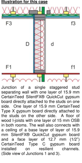
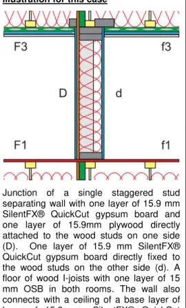
Junction of a single staggered stud separating wall with one layer of 15.9 mm CertainTeed SilentFX® QuickCut gypsum board directly attached to the studs on both sides. A floor of wood I-joists with one layer of 15 mm OSB in both rooms. The wall also connects with a ceiling of a base layer of layer of 15.9 mm SilentFX® QuickCut gypsum board and a face layer of 12.7 mm (1/2”) CertainTeed Type C gypsum board installed on resilient channels.
(Side view of Junctions 1 and 3).
Junction of a single staggered stud separating wall with side walls of triple staggered studs. One layer of 15.9 mm SilentFX® QuickCut gypsum board directly attached to the wood studs in both rooms. (Plan view of Junction 2 or 4).
Separating wall assembly (non-loadbearing) with:
Staggered 38 mm x 89 mm (2x4) wood studs spaced 400 mm on center. Double headers and a single footer 38 mm x 140 mm (2x6). One layer of 15.9 mm SilentFX® QuickCut gypsum board directly
attached to each side of the wood studs.
One layer of 89 mm thick CertainTeed R12 Sustainable Insulation® in the wall cavity.
Junction 1: Bottom Junction (separating wall / floor) with: Joists oriented parallel to the separating wall assembly.
Wood I-joists 241 mm (9.5”) deep spaced 406 mm (16”) on center. Doubled rim boards (32 mm (1-1/4”) thick and 241 mm deep) installed at each end of the I-joists.
Subfloor of 15 mm (19/32”) OSB directly attached to the I-joists. One layer of 152 mm thick CertainTeed R20 Sustainable Insulation®
in the floor cavity.
Junction 2 or 4: Each Side (separating wall /abutting side wall) with: Triple staggered 38 mm x 89 mm wood studs spaced 400 mm on
center. Double headers and a single footer 38 mm x 140 mm. One layer of 15.9 mm SilentFX® QuickCut gypsum board directly
attached to each side of the wood studs.
One layer of 89 mm thick CertainTeed R12 Sustainable Insulation® in the wall cavity.
Junction 3: Top Junction (separating wall / ceiling) with: Joists oriented parallel to the separating wall assembly.
Wood I-joists 241 mm (9.5”) deep spaced 406 mm (16”) on center. Doubled rim boards (32 mm (1-1/4”) thick and 241 mm deep) installed at each end of the I-joists.
Resilient channels installed perpendicular to wood I-joists and spaced 305 mm (12”) on center.
One layer of 152 mm thick CertainTeed R20 Sustainable Insulation® in the ceiling cavity.
Base layer of layer of 15.9 mm SilentFX® QuickCut gypsum board and a face layer of 12.7 mm (1/2”) CertainTeed Type C gypsum board installed on the resilient channels on the ceiling.
Room Parameters
See Figure 2 of this report or Figure 1.3 of the National Research Council Report RR-331.
The separating wall is 2.5 m high by 5 m wide. The flanking walls 2.5 m high by 4 m wide. The floor / ceilings are 4 m by 5 m.
Example 44 Reference Value
Direct STC Rating of Path Dd
Laboratory Measured STC Rating Report A1-007750.2 Appendix B 54
Junction 1 - Junction between the seperating wall and the floor assembly Flanking Path Ff_1
Reports A1-007750.2 and A1-012057.1 63
Normalization Correction RR-331 Eq. 1.5 3.98
RR-331 Eq. 1.5 67
Flanking Path Fd_1
Reports A1-007750.2 and A1-012057.1 72
Normalization Correction RR-331 Eq. 1.5 3.98
RR-331 Eq. 1.5 76
Flanking Path Df_1
Reports A1-007750.2 and A1-012057.1 72
Normalization Correction RR-331 Eq. 1.5 3.98
RR-331 Eq. 1.5 76
Flanking STC for Junction 1 66
Junction 2 - Junction between the separating wall and the flanking wall assemblies Flanking Path Ff_2
Report A1-007750.2 Appendix B, C, and D 69
Normalization Correction RR-331 Eq. 1.5 6.99
RR-331 Eq. 1.5 76
Flanking Path Fd_2
Report A1-007750.2 Appendix B, C, and D 72
Normalization Correction RR-331 Eq. 1.5 6.99
RR-331 Eq. 1.5 79
Flanking Path Df_2
Report A1-007750.2 Appendix B, C, and D 72
Normalization Correction RR-331 Eq. 1.5 6.99
RR-331 Eq. 1.5 79
Flanking STC for Junction 2 73
Junction 3 - Junction between the seperating wall and the ceiling assembly Flanking Path Ff_3
Reports A1-007750.2 and A1-012057.1 70
Normalization Correction RR-331 Eq. 1.5 3.98
RR-331 Eq. 1.5 74
Flanking Path Fd_3
Reports A1-007750.2 and A1-012057.1 70
Normalization Correction RR-331 Eq. 1.5 3.98
RR-331 Eq. 1.5 74
Flanking Path Df_3
Reports A1-007750.2 and A1-012057.1 70
Normalization Correction RR-331 Eq. 1.5 3.98
RR-331 Eq. 1.5 74
Flanking STC for Junction 3 69
Junction 4 - Junction between the separating wall and the flanking wall assemblies Flanking STC for Junction 4 - Same as Junction 2 73
54 ASTC due to Direct plus Flanking Transmission RR-331 Section 1.4
� � � � � � � � � � � � � � � � � �
Example 45: Rooms side-by-side - Non-loadbearing Separating Wall Simplified Method.
Common single staggered wood stud wall.
All other walls are triple staggered wood stud walls.
One layer of 15.9 mm (5/8”) CertainTeed SilentFX® QuickCut gypsum board fixed to the wood studs in one room.
One layer of 15.9 mm (5/8”) CertainTeed Type X fixed to the wood studs in the other room.
Fire rated floor BXUV.M5351 with a bare 15 mm OSB subfloor.2
Illustration for this case
Junction of a single staggered stud separating wall with one layer of 15.9 mm CertainTeed SilentFX® QuickCut gypsum board directly attached to the studs on one side. One layer of 15.9 mm CertainTeed Type X gypsum board directly attached to the studs on the other side. A floor of wood I-joists with one layer of 15 mm OSB in both rooms. The wall also connects with a ceiling of a base layer of layer of 15.9 mm SilentFX® QuickCut gypsum board and a face layer of 12.7 mm (1/2”) CertainTeed Type C gypsum board installed on resilient channels. (Side view of Junctions 1 and 3).
Junction of a single staggered stud separating wall with side walls of triple staggered studs. One layer of 15.9 mm SilentFX® QuickCut gypsum board directly attached to the wood studs in one room. One layer of 15.9 mm CertainTeed Type X gypsum board directly attached to the wood studs in the other room. (Plan view of Junction 2 or 4).
Separating wall assembly (non-loadbearing) with:
Staggered 38 mm x 89 mm (2x4) wood studs spaced 400 mm on center. Double headers and a single footer 38 mm x 140 mm (2x6). One layer of 15.9 mm SilentFX® QuickCut gypsum board directly
attached to one side of the wood studs and one layer of 15.9 mm CertainTeed Type X gypsum board directly attached to the other side of the wood studs.
One layer of 89 mm thick CertainTeed R12 Sustainable Insulation® in the wall cavity.
Junction 1: Bottom Junction (separating wall / floor) with: Joists oriented parallel to the separating wall assembly.
Wood I-joists 241 mm (9.5”) deep spaced 406 mm (16”) on center. Doubled rim boards (32 mm (1-1/4”) thick and 241 mm deep) installed at each end of the I-joists.
Subfloor of 15 mm (19/32”) OSB directly attached to the I-joists. One layer of 152 mm thick CertainTeed R20 Sustainable Insulation®
in the floor cavity.
Junction 2 or 4: Each Side (separating wall /abutting side wall) with: Tipple staggered 38 mm x 89 mm wood studs spaced 400 mm on
center. Double headers and a single footer 38 mm x 140 mm. One layer of 15.9 mm SilentFX® QuickCut gypsum board directly
attached to the wood studs in one room (F2 and F4).
One layer of 15.9 mm CertainTeed Type X gypsum board directly attached to the wood studs in the other room (f2 and f4).
One layer of 89 mm thick CertainTeed R12 Sustainable Insulation® in the wall cavities.
Junction 3: Top Junction (separating wall / ceiling) with: Joists oriented parallel to the separating wall assembly.
Wood I-joists 241 mm (9.5”) deep spaced 406 mm (16”) on center. Doubled rim boards (32 mm (1-1/4”) thick and 241 mm deep) installed at each end of the I-joists.
Resilient channels installed perpendicular to wood I-joists and spaced 305 mm (12”) on center.
One layer of 152 mm thick CertainTeed R20 Sustainable Insulation® in the ceiling cavity.
Base layer of layer of 15.9 mm SilentFX® QuickCut gypsum board and a face layer of 12.7 mm (1/2”) CertainTeed Type C gypsum board installed on the resilient channels on the ceiling.
Room Parameters
See Figure 2 of this report or Figure 1.3 of the National Research Council Report RR-331.
The separating wall is 2.5 m high by 5 m wide. The flanking walls 2.5 m high by 4 m wide. The floor / ceilings are 4 m by 5 m.