Publisher’s version / Version de l'éditeur:
Vous avez des questions? Nous pouvons vous aider. Pour communiquer directement avec un auteur, consultez la
première page de la revue dans laquelle son article a été publié afin de trouver ses coordonnées. Si vous n’arrivez pas à les repérer, communiquez avec nous à [email protected].
Questions? Contact the NRC Publications Archive team at
[email protected]. If you wish to email the authors directly, please see the first page of the publication for their contact information.
https://publications-cnrc.canada.ca/fra/droits
L’accès à ce site Web et l’utilisation de son contenu sont assujettis aux conditions présentées dans le site LISEZ CES CONDITIONS ATTENTIVEMENT AVANT D’UTILISER CE SITE WEB.
Proceedings of the 32nd Annual ACM Symposium on User Interface Software and
Technology, pp. 1045-1057, 2019-10-17
READ THESE TERMS AND CONDITIONS CAREFULLY BEFORE USING THIS WEBSITE. https://nrc-publications.canada.ca/eng/copyright
NRC Publications Archive Record / Notice des Archives des publications du CNRC :
https://nrc-publications.canada.ca/eng/view/object/?id=5f05ea1c-8aec-4b51-9829-457b7a56a9f4
https://publications-cnrc.canada.ca/fra/voir/objet/?id=5f05ea1c-8aec-4b51-9829-457b7a56a9f4
NRC Publications Archive
Archives des publications du CNRC
This publication could be one of several versions: author’s original, accepted manuscript or the publisher’s version. / La version de cette publication peut être l’une des suivantes : la version prépublication de l’auteur, la version acceptée du manuscrit ou la version de l’éditeur.
For the publisher’s version, please access the DOI link below./ Pour consulter la version de l’éditeur, utilisez le lien DOI ci-dessous.
https://doi.org/10.1145/3332165.3347907
Access and use of this website and the material on it are subject to the Terms and Conditions set forth at
Tip-Tap: battery-free discrete 2D fingertip input
Katsuragawa, Keiko; Wang, Ju; Shan, Ziyang; Ouyang, Ningshan; Abari,
Omid; Vogel, Daniel
Tip-Tap: Battery-free Discrete 2D Fingertip Input
Keiko Katsuragawa
1,2, Ju Wang
1, Ziyang Shan
1, Ningshan Ouyang
1, Omid Abari
1, Daniel Vogel
1 1School of Computer Science, University of Waterloo,
2National Research Council Canada
[email protected], {ju.wang, z7shan, nouyang, omid.abari, dvogel}@uwaterloo.ca
ABSTRACT
We describe Tip-Tap, a wearable input technique that can be implemented without batteries using a custom RFID tag. It recognizes 2-dimensional discrete touch events by sensing the intersection between two arrays of contact points: one array along the index fngertip and the other along the thumb tip. A formative study identifes locations on the index fnger that are reachable by different parts of the thumb tip, and the results determine the pattern of contacts points used for the technique. Using a reconfgurable 3×3 evaluation device, a second study shows eyes-free accuracy is 86% after a very short period, and adding bumpy or magnetic passive haptic feedback to contacts is not necessary. Finally, two battery-free prototypes using a new RFID tag design demonstrates how Tip-Tap can be implemented in a glove or tattoo form factor.
Author Keywords
interaction techniques; wearable input; RFID
INTRODUCTION
Creating wearable input devices that minimize movement for comfort [17, 25] and social acceptability [10, 21, 43] are important goals for researchers [11, 37] and entrepreneurs [26]. Using small fnger movements is perhaps the most subtle style of input, but can be challenging to sense reliably. Methods like mounting a camera on or near the hand [3, 14, 40], using sensors on a smartwatch [6], or magnetic feld sensing [4, 5] can track continuous movements of fngers, but all are limited by accuracy, bulk, and power demands.
Tip-Tap is an interaction technique and related RFID-based sensing method that simplifes fnger input to a discrete set of input events. By not pursuing fne-grained continuous input, the method can be robust, small, simple, and “battery-free” (meaning no power source is attached to the wearable device). The technique creates an addressable matrix of discrete input events by detecting different pinch points at the intersection of two arrays of contacts, mounted near the tips of the index fnger and thumb (Figure 1).
The positioning of contacts on the fnger and thumb tips is based on the results of a formative user study that identifed Permission to make digital or hard copies of all or part of this work for personal or classroom use is granted without fee provided that copies are not made or distributed for proft or commercial advantage and that copies bear this notice and the full citation on the frst page. Copyrights for components of this work owned by others than ACM must be honored. Abstracting with credit is permitted. To copy otherwise, or republish, to post on servers or to redistribute to lists, requires prior specifc permission and/or a fee. Request permissions from [email protected].
UIST’19,Oct 20–23, 2019, New Orleans, MS, USA © 2019 ACM. ISBN 978-1-4503-6816-2/19/10. . . $15.00 DOI: 10.1145/3332165.3347907
2,2 3,1
(a) (b) (c)
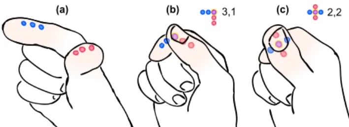
Figure 1. Tip-Tap showing 3×3 example: (a) arrays of discrete contact points along the index and thumb tips; (b and c) pressing thumb to index creates 9 different 2D inputs.
comfortable thumb-to-index-fnger pinch points. To explore performance and device variations, we built a 3×3 evaluation prototype with contacts that can be reconfgured for different types of passive haptic feedback. A controlled experiment compares time and accuracy when using contacts that felt smooth, bumpy, and with magnetic attraction. The results show a simple smooth-feeling design is comparable to using magnets for the fastest speed, and comparable to bumps for highest accuracy. To show Tip-Tap is practical for battery-free sensing, we created a novel RFID tag design featuring two half-antennas and multiple RFID chips. We use this design in two prototype Tip-Tap devices, a glove with a range of 4m, and an on-skin tattoo. Such devices are useful for issuing simple commands when a user cannot easily hold an input device and the usage context is a defned area. For example, factory workers, surgeons, or people exercising in a gym. We make three contributions: 1) a two-dimensional thumb-to-index fngertip input technique using two contact arrays; 2) empirical results for thumb-to-index reachable areas, perfor-mance, and how to design contacts; 3) an RFID-based method to recognize two-dimensional discrete input without a battery.
RELATED WORK
We focus on battery-free fnger sensing methods, and previous techniques and studies related to thumb-to-fnger input.
Sensing of Finger Input
A common approach is to use computer vision. Finger move-ments can be tracked precisely using motion tracking systems, but small retro-refective markers need to be attached [28]. These systems are typically only used for lab experiments or developing techniques for future high quality hand tracking. Current marker-less vision tracking, like the Leap Motion [1], or projects like Digits [14], need power if mounted on the body for wearable input. With vision-based methods in gen-eral, very fne fnger movements may be occluded by the hand or other fngers, and may be diffcult to track.
Non-vision approaches, like FinDroidHR [42] and Pyro [7], sense fnger movements using a wearable powered device, such as a smartwatch. Other technical approaches include magnetic-feld based sensing like Abracadabra [8] and mm-Wave based sensing like Soli [32]. However, these require a powered receiver or sensor to be placed nearby, typically 30 cm or less.
Battery-Free Sensing using RFID
Radio frequency identifcation (RFID) tags are common battery-free sensing methods that have a range up to several meters. For example, RFID tags have been attached to hands [30], and objects [38, 39, 44] to track coarse trajectories, but these methods are not able to track fne-grained movements like a thumb-to-fnger pinch. Pradhan et al. [23] detect touch and swipe on RFID tags using the Received Signal Strength (RSS) and phase of the signal. However, they require the tag to remain at a fxed location or else the calibrated RSS and phase will change, making this approach unsuitable for wearable input. Bainbridge and Paradiso [2] explored attaching WISP RFID tags and 3-axis accelerometers to each fnger for gesture recognition. However, they require attaching a powered tag reader and antenna to the arm and hand, which limits real-world applications. Moreover, a WISP tag is much more expensive than commodity RFID tags. To detect discrete input with RFID, several approaches for interactively enabling and disabling tags have been proposed. Marquardt et al. [20] demonstrated how to control access to information by connecting or disconnecting a single chip to an antenna. PaperID [15] enables a wide range of interactions by also connecting and disconnecting single chips to their anten-nas through various means. This system also supports using RSS for detecting continuous input, but as discussed above, RSS changes when a tag moves making it unsuitable for wear-able input. RFIBricks [9] extend the idea to simultaneously connecting or disconnecting multiple chips with their anten-nas. The resulting pattern of enabled tags is used to identify how large building blocks connect. RFIMatch [16] uses the simultaneous co-absence of two tags as an input event. Each tag is placed in a housing with a magnet and a magnetic reed switch that connects the tag to an antenna by default. When two tags approach, the magnets counteract causing the reed switches to disconnect both chips at the same time. Our ap-proach signifcantly extends the idea of enabling and disabling one or more single tags. We use patterns created when dif-ferent combinations of two chips connect to a single antenna, which unlike the works above, enables a dense 2D input space suitable for wearable fngertip input.
On-Skin Input
Related to our approach, techniques attaching input sensors directly on the skin have been proposed. iSkin [33] is a fexi-ble on-skin sensor using a low conductivity silicon polymer to enable discrete capacitive and resistive sensing with two levels of touch pressure. DuoSkin [12], Skintillates [18], and SkinMark [34] present different fabrication methods to create on-skin user interfaces that work as capacitive sensors. Skin-Mark [34] is also on-skin electronics enabled localization of on-skin widgets using tactile and visual feedback from body
landmarks like knuckles. These on-skin sensors are thin and light, and can support a reasonable density of about 1 com-mand per cm2. Although not used for input, Tacttoo [36] is a very thin material for multi-dimensional electro-tactile output on a fnger tip. It also requires external electronics and power. All of these methods require a power source and additional electronics like micro-controllers to also be worn or carried. They are not battery-free.
Thumb-to-Finger Interaction Techniques and Studies
Previous works allocate multiple commands to different fn-gers. DigiTouch [35] mapped up to 5 commands for each fnger on both hands to create a QWERTY keyboard. Con-ductive fabric mounted on the surface of each fnger of a thin glove is used for resistive sensing. DigiTap [24] mapped 3 commands to all four fngers, 12 commands in total. A wrist mounted mini camera is used to detect thumb to fnger tap events using computer vision. TIMMi [41] detects 3 discrete touch inputs at the side of the index fnger as well as fnger bending. A fnger worn textile made from conductive silicon rubber measures resistance. These input methods only dis-tinguish touch points on the fnger, not the thumb, meaning thumb-to-index input is one-dimensional.
Previous work identifed discrete thumb-to-index input as com-fortable, and provided guidelines for contact density. Pratorius et al. [24] and Huang et al. [11] show tapping on the proximal phalanx (the lower part of the fnger) is less comfortable than tapping on the distal phalanx (the tip), and that touching the thumb to the index or middle fnger is most comfortable. How-ever, these studies only evaluated pre-determined positions on the inside of the fngers without controlling for what part of the thumb was used to contact. Our reachability study controls for specifc thumb points for contacting, and our task seeks to map out the full range of how the thumb tip can contact to fnger tip. Some thumb-to-index fnger input systems allocate touch points at the side of the index fnger [27, 41], but we are not aware of any formative study that investigates thumb reachability to multiple sides of fngers.
EXPERIMENT 1: REACHABILITY
Our goal of the frst study is to identify which areas on the index fnger are comfortably reachable using different parts of the thumb. This extends Huang et al. [11] by not restricting fnger locations or surfaces a priori, and introducing a control for what part of the thumb is used.
Participants
We recruited 8 participants (5 males, 3 females, 1 left handed, ages 23 to 38). We measured various parts of their dominant thumb (Figure 2a): pad length h, top pad width tw, and bottom pad width bw. Participant thumbs had h from 26 to 34 mm, tw
from 22 to 25 mm, and bw from 26 to 32 mm. Apparatus
To measure the reachable area, participants wore latex exami-nation gloves (Figure 2d) and we recorded patterns made on the index fnger by a felt pad soaked with ink that was attached to different points on the thumb using magnets. The thumb part of the glove and remaining part of the glove with index
CT CM CB IT IB OT OB tw bw h h 5mm a b c d e f
Figure 2. Reachability Experiment: (a) thumb measurements; (b) method of attaching felt ink pad to glove using magnets; (c) position of 7 thumb points; (d) making marks on the index fnger during the ex-periment; (e) fattened index fnger part of glove; (f) area after scanning.
fnger were separate pieces, so we could reuse the thumb part and measure the fnger part. Three sizes of gloves were used: 2 participants used small, 4 used M, and 2 used L.
To precisely control the thumb points, seven small magnets (3.2 mm diameter × 0.8 mm thick) were attached to the inside
of the glove at the points we wished to test (Figure 2b). To record reachability of a specifc point, the felt pad had an embedded magnet to attach it to the corresponding point. The 7 thumb points are illustrated in Figure 2c: Centre-Bottom (CB) located 5 mm above the thumb joint; Centre-Top (CT) located h above the joint; Centre-Middle (CM) midway between CT
and CB; Inner-Top (IT) and Outer-Top (OT) located at extents of tw midway between CM and CT; and Inner-Bottom (IB) and
Outer-Bottom (OB) located at extents of tb midway between
CM and CB.
Study Procedure
The participant wore both parts of the glove on their dominant hand, and the felt ink pad was attached to the point to be tested. Then, they tapped their thumb on their index fnger in positions they could reach comfortably (Figure 2d). The experimenter traced the bounds of the inked area with a marker pen with the participant’s confrmation, this defned the reachable area. In addition, the fnger joints, centerline, and sidelines of the index were marked to enable calibration with other participants. The fnger part of the glove was changed, the felt moved to the next position on the thumb, and process was repeated. This was repeated for all 7 thumb points.
Analysis and Results
After the study, we cut off the index fnger part of the glove and opened it from the middle fnger side (Figure 2e). The center of the opened glove was the thumb side of the index fnger. We scanned all opened gloves (7 positions × 8
partici-pants = 56 gloves) and calibrated the images using the marked
Common Area OT CB CM CT IB IT OB
Figure 3. Heat maps showing the area where a specifc point on the thumb can touch an index fnger. IT, IB, CT, CM, CB, OT, and OB are the 7 thumb point positions tested (illustrated in Figure 2c). Blue coloured areas show where participants could reach, darker areas could be reached by more participants, the darkest “common area” is where all participants could reach. The red dotted line is the thumb side of the index fnger, black horizontal lines are fnger joints.
joint positions (Figure 2f). The results from the left-handed participant were fipped vertically.
Our result is Figure 3, a heat map showing areas of the in-dex fnger that can be comfortably reached by each thumb point. Horizontal black dashed lines represent the location of joints. Although fnger fexibility, and therefore reachability, varies among the participants, there were ‘common areas’ all participants could reach comfortably. The common area is emphasized with dark blue. The red dashed line indicates the side of the fnger, and the black dashed line at the left of the red line indicate the front center line of the fnger. Previous works [11, 24] reported lower comfort ratings for the lower section of the fnger and this was confrmed by our result as well. We did not fnd any common area at the palm side of the lower section of the fnger. However, our result suggests that participants have a wider comfort interaction area at the side of the fnger, than on the palm side of the fnger.
Comfortable Thumb-Index Interactions
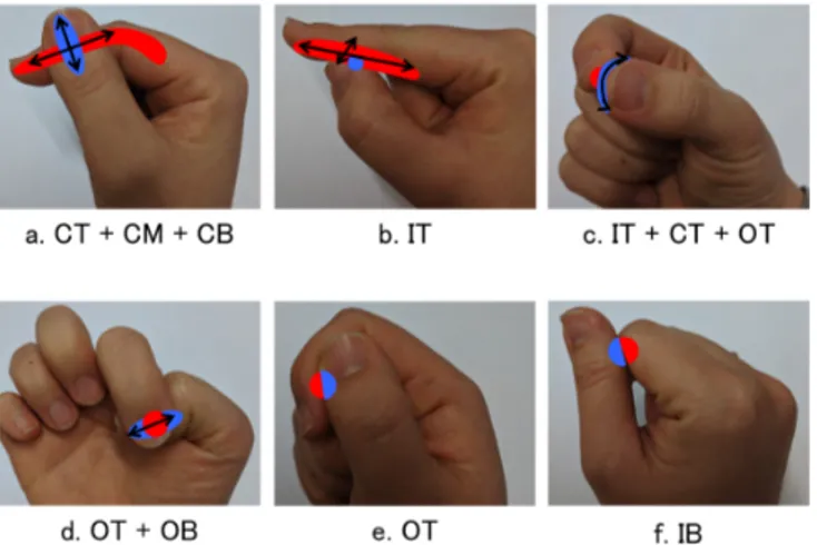
From the ‘common areas’ in Figure 3, we identify six sug-gested thumb-index touch interactions combining different thumb points and index fnger areas. All six areas can be used for thumb-to-index fnger discrete input, and some areas could be suitable for continuous input. Since our focus is simple battery-free sensing, we focus on discrete input.
Thumb Area and Index Finger Area
From the combination of CT, CM and CB of Figure 3, we see people can touch a wide range of the thumb side of the
Figure 4. Suggested thumb-index interactions: index fnger reachable area shown in red; thumb points shown in blue.
index fnger with any points at the center of the thumb (Figure 4a). With a combination of up-and-down movement of tip of index fnger and left-and-right movement of thumb, the contact point of the index fnger and the thumb can create 2 dimensional positioning. This is the largest interaction within all 6 interaction.
Thumb Point and Index Finger Area
The area reached by IT in Figure 3 indicates the upper inside part of the thumb can reach a wide range of the palm side of the index fnger (Figure 4b), confrming Huang et al. [11]. This thumb point to index fnger contact can be used for discrete input along with the index fnger [11] and the slide gesture input for continuous value input. The area reached by IT also indicates that the thumb can move along the width direction of the index fnger while the tip of the inside of the thumb touches the index fnger between the thumb side and the center of the palm side. Although this is a small distance, it can be used for swipe input (slide thumb left or right on the surface of the index fnger) or for confrmation or cancellation of a slide gesture.
Thumb Area and Index Finger Point
We also found two possible thumb area and index fnger point contacts. The combination of areas reachable by IT, CT and OT in Figure 3 indicate the top of the index fnger can reach both sides of the top of the thumb (Figure 4c). When the top of the index fnger slides around the thumb top, it creates a semicircle, suitable for dial input.
Touching the outside of the thumb from the nail side (Figure 4e) was a fnger position most of participants were not aware of until the experimenter asked if they could do it. This was likely because this is not a continuing position from any other fnger position. At the same time, this is similar to making a fst, which all the participants could make. Since this is a unique position from any others described here, it can be used for a binary switch or confrmation.
Thumb Point and Index Finger Point
With some areas of the thumb, participants could reach a limited area on the fnger. With the outside of the top of the
Figure 5. Reconfgurable evaluation device with smooth pad. Two termi-nals connect to complete a circuit for detection.
thumb, only a small part of the top of the fnger is reached by thumb point OT in Figure 3. Figure 4e shows a possible contact point of OT on the fnger. The area that can be reached with the lower inside part of thumb (IB) seems to vary between participants (Figure 3). Some participants could reach a wide area of the index fnger, but others could reach very limited area. At the end, the overlapping area of all participants was very limited. Overall, the area all participants could touch with IB on the index fnger was the area around the palm side of the second joint (Figure 4f).
When considering specifc touch points, our result shows com-fortable interaction areas all around one side of the fnger. Moreover, these areas take advantage of different thumb points for contact, so sensors located only on the index fnger [11, 24, 27, 41] would only distinguish some of the potential two-dimensional contact points possible by instrumenting both fnger and thumb. Utilizing the largest interaction area on the side of the index fnger (Figure 4a), Tip-Tap places arrays of contact sensors on both the thumb and fnger to detect a wider thumb-to-fnger touch input space.
RECONFIGURABLE EVALUATION DEVICE
Our ultimate goal is a battery-free device, but we frst created a powered prototype to evaluate input performance, and secon-darily, to test whether contacts need passive haptic feedback. The device has two 3-contact arrays to create a 3×3 matrix of possible input. We chose a 3×3 layout because it can be used like a discrete joystick (e.g. prev/next, up/down) or as 3 rows of related commands (e.g. volume, track, system). These two-dimensional semantic layouts are advantageous compared to a simpler linear layout.
We refer to these arrays as “pads,” and they can be reconfgured to provide smooth, bump, or magnetic haptic feedback. These represent the simplest forms of battery-free haptic feedback. More complex methods like vibration require a high-power electromagnetic feld and have a limited range [22].
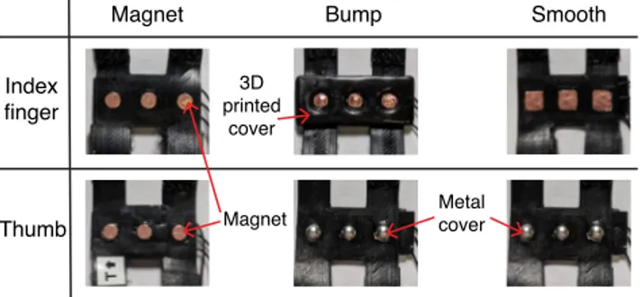
Each pad has three evenly spaced conductive contacts inserted into 3D printed non-conductive fexible material (Figure 5). Each pad attaches to the distal phalanges (the tips) of the
Index finger Thumb Smooth Bump Magnet Magnet 3D printed cover Metal cover
Figure 6. 3D printed fnger pads for three types of haptic feedback. The magnets were covered with adhesive copper tape. Copper tape were placed at the bottom of the indents of the bump pad. Each pad is con-nected to a connector plug with extra thin wires.
thumb and fnger using thin bands with hook and loop fasten-ers. The distance between the center of each contact is 7.5 mm and the width of the fnger pads is about 2 cm. The size of the pads were chosen to ft the participant with the smallest hand in the previous study. The contact density was guided by Huang et al. [11] who found the thumb can accurately se-lect 7 discrete points spread across the distal and intermediate phalanges of the index fnger (the tip and middle segments). Since our device uses only the distal phalanx, 3 discrete points is optimum.
Detection is by completing an electronic circuit. Each contact is conductive, with the thumb contacts connected to a 5 V power source and index contacts to ground. Extra thin core silicon-covered wires are used for connections to avoid affect-ing fnger range of motion. An Arduino board reads voltages for each contact, and streams values to a computer application which identifes touching contacts using a threshold.
Different Haptic Feedback Pads
We wished to test different types of passive haptic feedback since we suspected it may hard for people to register contacts from the thumb to the fnger reliably. For this reason, we created three sets of pads (Figure 6), two with simple haptic feedback (magnet, bump) and one “smooth” version as a no haptic feedback baseline.
Magnets – Magnets are a battery-free way to make passive
haptics feel “active”. Three small magnets are placed inside contacts with polarity oriented to create an attractive force between index and thumb. The magnets are cylindrical N52-grade Neodymium, each 0.8 mm thick and 3.2 mm diameter. Each is covered in copper tape to have a better connection with the core wire. Magnet strength was chosen to be noticeable, but not too powerful. In iterative testing, we tried thicknesses from 0.5 to 1.6 mm.
Bumps – For mechanical guidance, 4 mm hemispherical metal
bumps on the thumb are combined with slightly larger indent holes on the index. The bumps are half of a bead tip knot cover (a smooth metal part used for handmade accessories) and the indents are 3D printed and coated with UV-cured resin to make it smooth. One bump per contact can be considered the simplest form of possible haptic textures.
Smooth – To create a smooth feeling, the thumb pad bumps
are paired with a smooth index pad composed of three pieces of copper tape for contacts. Each of these square contacts are 4.5 × 4.5 mm. Note the index pad is thick enough that it does
not transmit any noticeable haptic feedback.
EXPERIMENT 2: PERFORMANCE
We use the reconfgurable prototype to evaluate input speed and accuracy for Tip-Tap input, as well as the effect of contacts with passive haptic feedback. Our expectation was that adding magnetic attraction, or bumps with mechanical ft to contacts would make it easier to align contacts by feel.
Participants
12 right-handed participants, recruited from the general student body of our institution, completed the experiment (9 male, 3 female, 23 to 28 years old). Each was remunerated with $10.
Apparatus and Task
The participant wore the reconfgurable device on their right hand, and was seated in front of a laptop computer. They completed multiple trials of tasks with and without real-time visual feedback. During both task trials, the participant kept their hand inside a box so they could not see the device.
Visual-Feedback Task
The objective of this task is to measure performance time with real-time interface feedback. The laptop displayed a stimulus indicating how to touch the two arrays of contacts together. When a contact-to-contact touch is detected by the device, the position is shown on the display (Figure 7 left). A blue border indicated the position matched the stimulus. To avoid counting accidental touches as the matched position, a touch was recorded as correct when held for at least 500 ms. Once the correct touch position was registered, the trial ended.
No-Visual-Feedback Task
The objective of this task is to measure time and accuracy without real-time visual feedback. This task is based on Huang et al.’s eyes-free thumb-to-fnger tapping accuracy test [11]. As before, the computer displayed a stimulus indicating how to touch the two arrays of contacts together. However, no visual feedback was given for the recognized touch position aside from a grey border indicating that two contacts were touching (Figure 7 right). To confrm the touch position is their fnal position, the participant pressed space on the keyboard. After confrmation, the same feedback from the visual-feedback task was displayed (Figure 7 left) with a blue border indicating the position was correct and a red border otherwise. This enabled participants to learn the correct positions.
Design and Procedure
This is a within subject design, with two sequential task con-ditions: visual-feedback and no-visual-feedback. Each part had 1 block of practice trials and 5 blocks of timed trials. The independent variable is HAPTIC condition with three levels:
MAGNET, BUMP, SMOOTH.
The order of HAPTIC was counterbalanced, and for each haptic
condition, the visual-feedback task preceded the no-visual-feedback task as a form of training. Before each HAPTIC
condition, participants familiarized themselves with the type of haptic feedback, adjusted the position of the fnger pads, and completed practice trials. This typically took one to fve minutes, but for their very frst condition, some participants spent up to 10 minutes on this phase.
Within a block, 9 trials represented every one of the 9 possible positions created by the two three contact arrays. The order of trials was randomized. To avoid the effect of the distance from the previous trial, our experiment system moved to the next trial only after the user released their fngers from the previous trial position more than 500 ms. All sensor readings, system events (trial initiation), and user events (touches, key inputs) were logged with timestamps.
The task completion time dependent measure for the
visual-feedback task is defned as the duration from the time when the contact position was shown on the display until the touch event matched the correct position. The 500 ms dwell time was not included. For the no-visual-feedback task, task completion
time was defned as the duration from the trial initiation until
the last touch event before the space key, and only correct trials are used.
The no-visual-feedback task also has a dependent measure of input accuracy, defned as the proportion of trials in a block
that were correct. Note there is no accuracy measure for the visual-feedback condition since all trials had to be completed correctly.
We treated the frst block of each task as training and excluded its data from analysis. In summary, 3 HAPTIC types × 5
BLOCKS × 9 positions × 12 participants = 1,620 data points
for each task variation.
Results
We removed outlier data points with selection times more than 3 standard deviations from the task mean. This removed 56 (1.73%) data points in total. A one-way ANOVA with Holm-Bonferroni corrected post hoc pairwise t-tests is used for all analysis. When sphericity was violated, degrees of freedom were corrected using Greenhouse-Geisser (ε < 0.75).
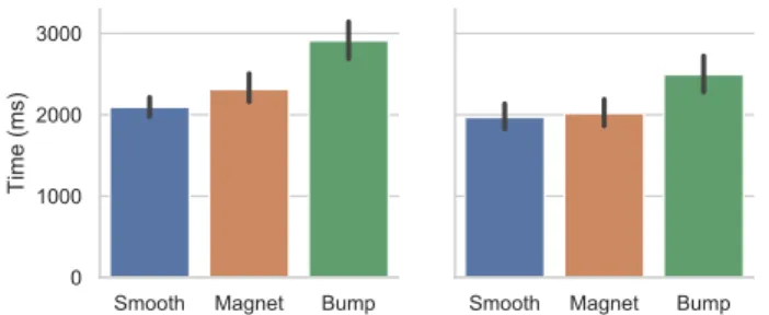
Task Completion Time
In the visual-feedback task, using smooth contacts is 28% faster than using bump feedback (Figure 8 left). There was a signifcant main effect for HAPTIC on task completion time
(F2,22 = 4.87, p = .018. Post hoc pairwise comparisons revealed
signifcant differences between BUMP (2910 ms) and SMOOTH
(2094 ms) (p = .017). We also found the two top rows of con-tacts accessed using the top of the thumb were faster than the
Figure 7. Experiment 2 user interface: (left) visual-feedback task showing stimulus and real-time feedback during trial; (right) no-visual-feedback task where only stimulus is shown during trial.
Figure 8. Task completion time by HAPTIC conditions: (left) visual-feedback task; (right) no-visual-visual-feedback task. Error bars are 95% CI.
Figure 9. Input Accuracy by HAPTIC in no-visual-feedback task. Error bars are 95% CI.
bottom row accessed using the heel of the thumb: 2192 ms and 2315 ms versus 2821 ms (all p < .001).
With the no-visual-feedback task, using smooth contacts is comparable in terms of time to other haptic conditions (Figure 8 right). There was no signifcant main effect for HAPTIC
on task completion time (F2,22 = 2.54, p = .10). Note the
visual-feedback task result included correction time. If all trials with an initial wrong touch are removed, visual-feedback is only 500 ms slower than no-visual-feedback.
Input Accuracy
Input accuracy only applies to the no-visual-feedback task. Us-ing smooth contacts or bump haptic feedback is more accurate than using magnetic feedback when no real-time feedback is provided (Figure 9). A repeated-measures ANOVA revealed
HAPTIC has signifcant effect on input accuracy (F2,22 = 8.35, p < .01). Post hoc pairwise comparisons revealed signifcant differences between BUMP (86.3%) and MAGNET (76.2%) (p < .001) as well as SMOOTH (86.4%) and MAGNET (p < .001).
User Preference
At the end of the experiment, participants were asked what kind of haptic feedback they preferred overall: 6 chose MAG
-NET, 5 chose SMOOTH, and one chose BUMP. Some of the participants who did not chose smooth said it was hard to locate their fngers at the correct position without any haptic feedback: with MAGNET or BUMP they had a good idea when two contacts were aligned. Those who preferred MAGNET , said it felt more discrete.
However, participants also stated it was easier to move their fnger around a smooth surface. Passing over intermediate contacts meant they had to overcome magnetic attraction or slide the bump out of an indent, which made the task more tiring. Many said MAGNET forced them to align the desired contacts with fnger and thumb slightly separated, and that
made the task more diffcult. There is some evidence that participants landed on more incorrect contacts before selecting the right one in the visual-feedback task. The average number of pad contacts before the fnal contact was: 0.89 for BUMP, 0.95 for MAGNET, and 0.67 for SMOOTH.
Discussion
Contrary to our expectation, a simple smooth contact design with no passive haptic feedback works well. In terms of quan-titative measures, smooth contacts are comparable to adding magnets in terms of the highest measured speeds, and compara-ble to using contacts with bumps in terms of highest accuracy. User preference also suggests little difference between smooth contacts and magnets, but more pronounced dislike for bumps. Based on observations and comments, we think this pattern of results is related to how magnets and bumps affect pointing movements. Common strategies were “touch anywhere and then correct” and “try for correct position on frst touch”. The problem is that bumps make longer movements diffcult due to “friction” created when each contact bump on the thumb is momentarily caught inside an intermediate contact indent on the fnger. The attractive force of magnets is less discrete, so these fast movements are easier. However, during a slow corrective movement, the pull of the magnet becomes more pronounced, and can snap to the wrong contact. The smooth profle of the bumps meant nearby contact boundaries can be “felt” before committing. As we explained in the results section, these problems with magnet and bump often led some participants to adopt a less optimal strategy, where they kept their fnger and thumb slightly separated until they made a fnal pinch to select.
The mean time for selection with smooth contacts is 2.1s in the visual-feedback task, somewhat slower than expected. We believe this is partly due to some participants pausing at in-termediate contact positions during the task. To see how this may have affected the time, we examined task completion times where participants only registered a single contact po-sition (54.5% of all trials). This reduces the mean time for smooth contacts to 1.5s, and a signifcant haptic main effect (F2,22 = 5.70, p = .025) but no signifcant differences in corrected
post hoc tests.
In terms of overall accuracy, our results are comparable to Huang et al. They show selecting among 3 to 4 one-dimensional positions on the distal phalanx can have more than 90% accuracy, but when also selecting additional po-sitions on the middle phalanx, accuracy drops to less than 60% [11]. Tip-Tap accuracy is comparable to one-dimensional input with 6-7 positions, but with more nuanced 2D input creating 9 positions. Placing all input contacts on the distal phalanx of the index fnger likely contributed to higher accu-racy compared to Huang et al.’s results for fewer positions spanning two segments of the fnger.
Tip-Tap achieved higher accuracy than Huang et al. [11], but 86% is likely not suitable for critical operations. However, if commands can be easily reverted, corrected, or attempted a second time, it may be fne. For example, volume up/down when exercising, or page next/prev to navigate content.
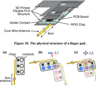
More-8cm 3D Printed Flexible PLA Structure PCB Board RFID Chip Core Wire Antenna
Solder Contact
Figure 10. The physical structure of a fnger pad.
chips contacts 8cm antenna 2,2 3,1 (a) (b) (c)
Figure 11. Custom multi-chip RFID tag: (a) each fnger pad has 3 chips connected to half of a dipole antenna, and each chip is connected to a contact; (b), (c) when contacts on two pads touch, a full dipole antenna is created and one chip in each pad is activated to detect a 2D position.
over, our results are average accuracy across all participants. It is notable that two participants already reached 95% in the Smooth condition, so more training would surely lead to higher average accuracy.
BATTERY-FREE TIP-TAP DEVICE USING RFID
In this section, we describe two functioning prototypes for battery-free sensing of Tip-Tap using a custom designed pas-sive RFID tag.
RFID is an automatic identifcation and data capture mecha-nism using the radio frequency electromagnetic feld. Passive RFID tags are battery-free, low cost (few cents) and commonly used in settings like retail stores to prevent shoplifting and track inventory levels of individual items. Each passive RFID tag stores a unique ID. An RFID reader can read the ID from a relatively long distance (up to 10 m). A passive RFID tag consists of a chip and an antenna. The antenna receives the reader’s radio wave and powers up the chip. If the chip is de-coupled from the antenna or the part of the antenna is missing, the RFID tag cannot respond to the reader. This feature can be used as a switch [15, 29], or disabling tag by detaching the chip from the antenna [13].
We use this coupling mechanism between the RFID chip and the antenna for our implementation. We note that using an RFID tag as a switch is not novel. However, past work (e.g. [9, 15, 20]) require a full RFID tag (one antenna and one chip) for each touch state which makes the design quite large for our target fngertip application. In contrast, we designed a custom multi-chip RFID tag consisting of a single antenna and a matrix of 6 chips to detect nine distinct touch states.
Custom Multi-chip RFID Tag
The Tip-Tap device has two fnger pads, each composed of 3 RFID chips and half of a dipole antenna (Figure 10). To each half-antenna, we connect three commercially available UHF
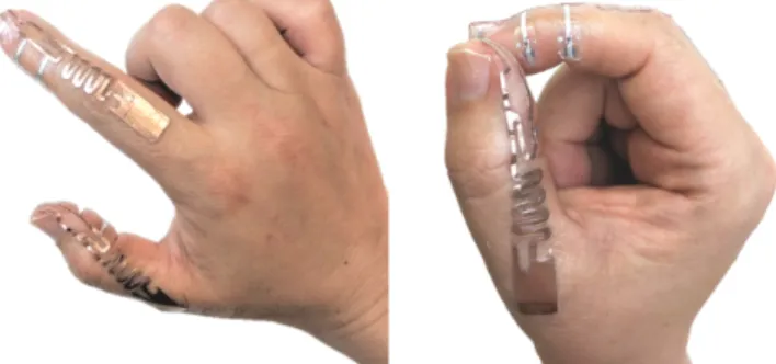
Figure 12. RFID Tip-Tap device on a glove with smooth pads. Pressing thumb and index contacts together connects two RFID chips in series, and two fexible core wires work as a single dipole antenna.
RFID chips (Alien Higgs-3 SOT IC). Specifcally, for each RFID chip, one terminal is connected to the half-antenna, and the other terminal is left open. When an open terminal of a chip with a half-antenna touches the open terminal of a chip attached to the other half-antenna (Figure 11), a complete an-tenna circuit is created, and two RFID chips will be connected in series to a single antenna. When the tag’s antenna receives the RF signal, it resonates and generates current which goes through only the two chips which are in series with the antenna. Therefore, only those two chips respond.
By attaching one fnger pad to the index fnger, and another one to the thumb, we can detect 2D positions. Using two half-antennas that activate only two chips when connected to form a circuit is mechanically simple and reduces space compared to using a full-antenna for each chip with switches for activation. We use this approach in two device Tip-Tap prototypes: on gloves, and as an on-skin tattoo.
Tip-Tap Device on Gloves
We use fexible wire with a length of ∼8 cm (i.e. half a wavelength of the RFID signal) as half of a dipole antenna. We solder three RFID chips to each wire. Specifcally, each RFID chip has two terminals, we solder one terminal of the chip to the wire and leave the other open. For the thumb pad, we solder metal bumps on the RFID chips’ open terminals, and for the index fnger pad, we place small fat metal pieces covered with copper sheet on the chip’s open terminal to create a smooth surface (Figure 12). We 3D print a fexible PLA structure to hold the chips on the fnger. Finally, we route the half-antennas to the back of gloves to minimize the attenuation of radio frequency (RF) signals by the hand.
Tip-Tap Device on Skin
Inspired by previous work [12, 18, 34], we use temporary tattoo paper to apply our custom multi-chip RFID tag directly to the user’s hand (Figure 13). To make the half-antennas, we created a modifed shape based on Alien Squiggle ALN-9740 RFID tags. These are more compact and durable than an 8 cm dipole antenna, important qualities for a tattoo. To reduce how much the body absorbs and dissipates RF energy, we used long connection traces between the chips and the half-antennas to minimize tag occlusion. A desktop vinyl cutting
Figure 13. RFID Tip-Tap device as an on-skin tattoo. Each contact array has 3 RFID chips connected to a copper tape half-antenna shaped like half of a ALN-9740 RFID tag.
machine is used to cut the copper tape into the half-antenna shapes, and these are placed on tattoo papers. Note that Kao et al. [12] found tattoo paper did not adhere to copper tape, but we found it worked well. One terminal of each RFID chip is attached to a loop section of each half antenna and a small magnet is placed behind the other chip terminal to create a reliable contact. The two tattoo papers, each with 3 chips and a half-antenna, are affxed to the skin with temporary tattoo adhesive.
Software and System Confguration
For an UHF RFID reader, we use the IMPINJ Speedway Revo-lution R420 with a panel RFID antenna (S9028PCR/S8658PR). Whenever the reader detects any RFID chip, it sends the chip ID to a notebook computer using the Octane SDK .NET (ver-sion 2.30.2) via an Ethernet cable. The RFID reader operates at 30 dBm, and complies with Federal Communications Com-mission (FCC) regulations. We developed software that knows the ID map of the chips on the two RFID fnger pads. When-ever the software detects a pair of chip IDs on the index fnger and thumb, the software recognizes a touch event and what part of each contact array is touching.
Performance
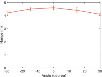
The accompanying video demonstrates both devices. The working range of the on-glove device was tested in our lab at different positions within a 60◦ arc centred on the reader. We measured the maximum distance from the reader where all 9 touch locations could still be detected. This was repeated 10 times. Our results found the maximum range to be approxi-mately 4 m for the on-glove device (see Appendix for details). Using a simpler procedure, we found the maximum range of the on-skin device to be 0.5 m. For comparison, when the RFID chip used in the devices is attached to a single dipole antenna, the maximum read distance is 7 m.
We believe these shorter ranges, compared to a single chip and antenna, are mainly due to powering two chips with one antenna and placing the antenna near the body. The insulating property of the glove mitigates this affect enough to make its range practical for many applications. However, the on-skin version demonstrates how challenging it is to use RFID when mounted very close to the body. Placing an antenna near or directly on the body signifcantly changes its impedance, causing impedance mismatch between the RFID chips and the
antenna. Furthermore, connecting two chips in series no doubt exacerbated the impedance mismatch problem.
Impedance mismatch is not a fundamental problem, and we believe it can be further improved by designing a custom on-body antenna design with a matching circuit to maximize power transfer from the antenna to the chips by matching their impedance. Moreover, new RFID beamforming techniques have improved RFID range by a factor of 4 or 5 [19, 31], suggesting the range of our on-skin prototype could increase to 2 to 3 m. The exploration of these range boosting methods is an interesting area for future research, but it was not the focus for our proof-of-concept.
In terms of mechanical robustness, the contact method for the glove version is very similar to the tethered reconfgurable prototype device used in Experiment 2. That device has been used for dozens of hours during testing, piloting, and develop-ment, so we believe this simple design is likely to be reliable. We would not expect the a temporary tattoo version to be as robust. However, our antenna shapes are designed to enable placement such that they avoid areas of high joint movement. During development, this device lasted more than 8 hours after application, even surviving a few hand washes.
Applications
Our two example devices suggest applications for Tip-Tap interaction. For example, factory workers and machine opera-tors often wear thick work gloves, making it hard to control small switches or use a keyboard or touch panel. With an on-glove Tip-Tap device, they could issue key commands (e.g. stop, start, next, previous, etc.) to a nearby display or control panel without taking off their gloves or approaching it. The on-skin version could be applied to thin latex gloves, so lab workers, or surgeons could issue commands to a computer. For example, surgeons could navigate a 3D scan of the pa-tient’s anatomy used to guide a complex procedure (e.g. up, down, left, right, in, out, prev, next. etc.). With Tip-Tap, there is no contamination risk from using a touch screen or mouse, the commands can be issued in a subtle way without mov-ing far from the surgical site, and the cost of Tip-Tap gloves would be low enough that they can be discarded after use (as is common practice for surgical gloves now).
Other applications could be for non-work activites and enter-tainment. For example, a Tip-Tap device could be used during gym-based exercise to control a music player, adjust machine speed, and monitor exercise progress, all without changing posture or balance mid-exercise. RFID reader antennas could be placed in exercise machines to work with on-skin Tip-Tap, or multiple antennas could be mounted throughout the gym while the user wears Tip-Tap weight-lifting gloves. Museum or amusement park patrons could receive a disposable Tip-Tap glove on admission, then reader antennas mounted in exhibits or rides would enable manipulating exhibit information, an-swering quizzes, or playing simple games. Finally, in movie theaters where smartphone use is discouraged, multiple reader antennas mounted in seats would allow interactive audience participation with Tip-Tap.
In general, RFID is only applicable when used in a well-defned area. Despite this limitation, RFID has many advan-tages: it is cheap and available; small and fexible; the range can be increased with more reader antennas; and it has robust sensing due to simplicity and limited environment interference. Because Tip-Tap can be mounted in a (possibly disposable) glove, it is simple to instrument the user, especially if they already wear gloves in a target application.
CONCLUSION
We described Tip-Tap, an interaction technique and related sensing method that simplifes fnger input to a discrete set of input events. The design was shaped by an investigation of reachable areas on the index fnger using different points on the thumb tip. This revealed six possible thumb-to-index-fnger interactions. A second experiment using a reconfgurable eval-uation device found participants could select positions with 86% accuracy without looking, even though this was with a rel-atively short training time. In addition, the results show more elaborate haptic feedback methods appear unnecessary, us-ing simple smooth contacts was comparable to other methods with the highest accuracy and fastest time. Informed by these experiments, two prototype Tip-Tap devices were created, a glove and a temporary tattoo, to demonstrate the feasibility of battery-free two-dimensional discrete fnger tip input. Both devices feature a new type of custom RFID tag using two half-antennas and multiple chips in two arrays,
Our exploration focused on nine discrete inputs. Extending to more than 9 contacts (using larger contact arrays) may reduce input accuracy and increase antenna design complexity. However, assigning one command to each contact combination is only a basic interaction. For example, recognizing double-taps or triple-double-taps on the same contacts would extend the input space. Using touch patterns as simple gestures, such as a quick succession of touches across all three contacts from left-to-right, would enlarge the input space even further. Although our input method is fundamentally discrete, we be-lieve it is still expressive. Considering it can be realized in a simple, low-cost, and battery-free wearable form factor, we think the trade-off compared to high-resolution, continuous wearable input that requires a power source is compelling.
ACKNOWLEDGEMENTS
This work made possible by the NRC-Waterloo Collaboration on Artifcial Intelligence, Internet of Things, and Cybersecu-rity program 927517 “Battery-Free Touch Sensors for Inter-net of Things (IOT)”, the NSERC USRA Program for under-graduate research, NSERC Discovery Grants 2018-05187 and 2018-05269, the Canada Foundation for Innovation Infrastruc-ture Fund 33151 “Facility for Fully Interactive Physio-digital Spaces,” and Ontario Early Researcher Award ER16-12-184.
REFERENCES
[1] 2018. Leap Motion. (2018). https://www.leapmotion.com
[2] Rachel Bainbridge and Joseph A Paradiso. 2011. Wireless Hand Gesture Capture through Wearable Passive Tag Sensing. In 2011 International Conference
on Body Sensor Networks. 200–204. DOI:
http://dx.doi.org/10.1109/BSN.2011.42
[3] Liwei Chan, Yi-Ling Chen, Chi-Hao Hsieh, Rong-Hao Liang, and Bing-Yu Chen. 2015. CyclopsRing: Enabling Whole-Hand and Context-Aware Interactions Through a Fisheye Ring. In Proceedings of the 28th Annual ACM
Symposium on User Interface Software and Technology
(UIST ’15). ACM, New York, NY, USA, 549–556. DOI:
http://dx.doi.org/10.1145/2807442.2807450
[4] Liwei Chan, Rong-Hao Liang, Ming-Chang Tsai, Kai-Yin Cheng, Chao-Huai Su, Mike Y Chen, Wen-Huang Cheng, and Bing-Yu Chen. 2013. FingerPad: Private and Subtle Interaction Using Fingertips. In Proceedings of the 26th Annual ACM
Symposium on User Interface Software and Technology
(UIST ’13). ACM, New York, NY, USA, 255–260. DOI:
http://dx.doi.org/10.1145/2501988.2502016
[5] Ke-Yu Chen, Kent Lyons, Sean White, and Shwetak Patel. 2013. uTrack: 3D Input Using Two Magnetic Sensors. In Proceedings of the 26th Annual ACM
Symposium on User Interface Software and Technology
(UIST ’13). ACM, New York, NY, USA, 237–244. DOI:
http://dx.doi.org/10.1145/2501988.2502035
[6] Jun Gong, Xing-Dong Yang, and Pourang Irani. 2016. WristWhirl: One-handed Continuous Smartwatch Input Using Wrist Gestures. In Proceedings of the 29th
Annual ACM Symposium on User Interface Software
and Technology (UIST ’16). ACM, New York, NY, USA,
861–872. DOI:
http://dx.doi.org/10.1145/2984511.2984563
[7] Jun Gong, Yang Zhang, Xia Zhou, and Xing-Dong Yang. 2017. Pyro: Thumb-Tip Gesture Recognition Using Pyroelectric Infrared Sensing. In Proceedings of the
30th Annual ACM Symposium on User Interface
Software and Technology (UIST ’17). ACM, New York,
NY, USA, 553–563. DOI:
http://dx.doi.org/10.1145/3126594.3126615
[8] Chris Harrison and Scott E Hudson. 2009. Abracadabra: Wireless, High-precision, and Unpowered Finger Input for Very Small Mobile Devices. In Proceedings of the
22nd Annual ACM Symposium on User Interface
Software and Technology (UIST ’09). ACM, New York,
NY, USA, 121–124. DOI:
http://dx.doi.org/10.1145/1622176.1622199
[9] Meng-Ju Hsieh, Rong-Hao Liang, Da-Yuan Huang, Jheng-You Ke, and Bing-Yu Chen. 2018. RFIBricks: Interactive Building Blocks Based on RFID. In
Proceedings of the ACM Conference on Human Factors
in Computing Systems (CHI ’18). ACM, New York, NY,
USA, 189:1–189:10. DOI:
http://dx.doi.org/10.1145/3173574.3173763
[10] Yi-Ta Hsieh, Antti Jylhä, Valeria Orso, Luciano Gamberini, and Giulio Jacucci. 2016. Designing a Willing-to-Use-in-Public Hand Gestural Interaction Technique for Smart Glasses. In Proceedings of the ACM
Conference on Human Factors in Computing Systems
(CHI ’16). ACM, New York, NY, USA, 4203–4215.
DOI:http://dx.doi.org/10.1145/2858036.2858436
[11] Da-Yuan Huang, Liwei Chan, Shuo Yang, Fan Wang, Rong-Hao Liang, De-Nian Yang, Yi-Ping Hung, and Bing-Yu Chen. 2016. DigitSpace: Designing
Thumb-to-Fingers Touch Interfaces for One-Handed and Eyes-Free Interactions. In Proceedings of the ACM
Conference on Human Factors in Computing Systems
(CHI ’16). ACM, New York, NY, USA, 1526–1537.
DOI:http://dx.doi.org/10.1145/2858036.2858483
[12] Hsin-Liu (Cindy) Kao, Christian Holz, Asta Roseway, Andres Calvo, and Chris Schmandt. 2016. DuoSkin: Rapidly Prototyping On-skin User Interfaces Using Skin-friendly Materials. In Proceedings of the 2016
ACM International Symposium on Wearable Computers
(ISWC ’16). ACM, New York, NY, USA, 16–23. DOI:
http://dx.doi.org/10.1145/2971763.2971777
[13] Günter Karjoth and Paul A Moskowitz. 2005. Disabling RFID Tags with Visible Confrmation: Clipped Tags Are Silenced. In Proceedings of the 2005 ACM Workshop on
Privacy in the Electronic Society (WPES ’05). ACM,
New York, NY, USA, 27–30. DOI:
http://dx.doi.org/10.1145/1102199.1102205
[14] David Kim, Otmar Hilliges, Shahram Izadi, Alex D Butler, Jiawen Chen, Iason Oikonomidis, and Patrick Olivier. 2012. Digits: Freehand 3D Interactions Anywhere Using a Wrist-worn Gloveless Sensor. In Proceedings of the 25th Annual ACM Symposium on
User Interface Software and Technology (UIST ’12).
ACM, 167–176. DOI:
http://dx.doi.org/10.1145/2380116.2380139
[15] Hanchuan Li, Eric Brockmeyer, Elizabeth J Carter, Josh Fromm, Scott E Hudson, Shwetak N Patel, and Alanson Sample. 2016. PaperID: A Technique for Drawing Functional Battery-Free Wireless Interfaces on Paper. In Proceedings of the ACM Conference on Human Factors
in Computing Systems (CHI ’16). ACM, New York, NY,
USA, 5885–5896. DOI:
http://dx.doi.org/10.1145/2858036.2858249
[16] Rong-Hao Liang, Meng-Ju Hsieh, Jheng-You Ke, Jr-Ling Guo, and Bing-Yu Chen. 2018. RFIMatch: Distributed Batteryless Near-Field Identifcation Using RFID-Tagged Magnet-Biased Reed Switches. In Proceedings of the 31st Annual ACM Symposium on
User Interface Software and Technology (UIST ’18).
ACM, New York, NY, USA, 473–483. DOI:
http://dx.doi.org/10.1145/3242587.3242620
[17] Mingyu Liu, Mathieu Nancel, and Daniel Vogel. 2015. Gunslinger: Subtle Arms-down Mid-air Interaction. In Proceedings of the 28th Annual ACM Symposium on
User Interface Software and Technology (UIST ’15).
ACM, 63–71. DOI:
http://dx.doi.org/10.1145/2807442.2807489
[18] Joanne Lo, Doris Jung Lin Lee, Nathan Wong, David Bui, and Eric Paulos. 2016. Skintillates: Designing and Creating Epidermal Interactions. In Proceedings of the
2016 ACM Conference on Designing Interactive Systems
(DIS ’16). ACM, New York, NY, USA, 853–864. DOI:
http://dx.doi.org/10.1145/2901790.2901885
[19] Yunfei Ma, Zhihong Luo, Christoph Steiger, Giovanni Traverso, and Fadel Adib. 2018. Enabling Deep-tissue Networking for Miniature Medical Devices. In
Proceedings of the 2018 Conference of the ACM Special
Interest Group on Data Communication (SIGCOMM
’18). ACM, New York, NY, USA, 417–431. DOI:
http://dx.doi.org/10.1145/3230543.3230566
[20] Nicolai Marquardt, Alex S Taylor, Nicolas Villar, and Saul Greenberg. 2010. Rethinking RFID: Awareness and Control for Interaction with RFID Systems. In
Proceedings of the ACM Conference on Human Factors
in Computing Systems (CHI ’10). ACM, New York, NY,
USA, 2307–2316. DOI:
http://dx.doi.org/10.1145/1753326.1753674
[21] Jess McIntosh, Charlie McNeill, Mike Fraser, Frederic Kerber, Markus Löchtefeld, and Antonio Krüger. 2016. EMPress: Practical Hand Gesture Classifcation with Wrist-Mounted EMG and Pressure Sensing. In
Proceedings of the ACM Conference on Human Factors
in Computing Systems (CHI ’16). ACM, New York, NY,
USA, 2332–2342. DOI:
http://dx.doi.org/10.1145/2858036.2858093
[22] Jess McIntosh, Paul Strohmeier, Jarrod Knibbe, Sebastian Boring, and Kasper Hornbæk. 2019. Magnetips: Combining Fingertip Tracking and Haptic Feedback for Around-Device Interaction. In
Proceedings of the ACM Conference on Human Factors
in Computing Systems (CHI ’19). ACM, New York, NY,
USA, 408:1–408:12. DOI:
http://dx.doi.org/10.1145/3290605.3300638
[23] Swadhin Pradhan, Eugene Chai, Karthikeyan
Sundaresan, Lili Qiu, Mohammad A Khojastepour, and Sampath Rangarajan. 2017. RIO: A Pervasive
RFID-based Touch Gesture Interface. In Proceedings of
the 23rd Annual International Conference on Mobile
Computing and Networking (MobiCom ’17). ACM, New
York, NY, USA, 261–274. DOI:
http://dx.doi.org/10.1145/3117811.3117818
[24] Manuel Prätorius, Dimitar Valkov, Ulrich Burgbacher, and Klaus Hinrichs. 2014. DigiTap: An Eyes-free VR/AR Symbolic Input Device. In Proceedings of the
20th ACM Symposium on Virtual Reality Software and
Technology (VRST ’14). ACM, New York, NY, USA,
9–18. DOI:http://dx.doi.org/10.1145/2671015.2671029
[25] Shaishav Siddhpuria, Keiko Katsuragawa, James R Wallace, and Edward Lank. 2017. Exploring At-Your-Side Gestural Interaction for Ubiquitous Environments. In Proceedings of the 2017 Conference
on Designing Interactive Systems (DIS ’17). ACM, New
York, NY, USA, 1111–1122. DOI:
http://dx.doi.org/10.1145/3064663.3064695
[26] Statista. 2018. Statistics & Facts on Wearable Technology. (2018). https:
//www.statista.com/topics/1556/wearable-technology/
[27] Koji Tsukada and Michiaki Yasumura. 2002. Ubi-Finger : Gesture Input Device for Mobile Use. In Proceedings of APCHI 2002, Vol. 1. 388–400.
[28] Daniel Vogel and Ravin Balakrishnan. 2005. Distant Freehand Pointing and Clicking on Very Large, High Resolution Displays. In Proceedings of the 18th Annual
ACM Symposium on User Interface Software and
Technology (UIST ’05). ACM, 33–42. DOI:
http://dx.doi.org/10.1145/1095034.1095041
[29] Ju Wang, Omid Abari, and Srinivasan Keshav. 2018. Challenge: RFID Hacking for Fun and Proft. In Proceedings of the 24th Annual International
Conference on Mobile Computing and Networking.
ACM, 461–470. DOI:
http://dx.doi.org/10.1145/3241539.3241561
[30] Jue Wang, Deepak Vasisht, and Dina Katabi. 2014. RF-IDraw: Virtual Touch Screen in the Air Using RF Signals. In Proceedings of the 2014 ACM Conference on
SIGCOMM (SIGCOMM ’14). ACM, New York, NY,
USA, 235–246. DOI:
http://dx.doi.org/10.1145/2619239.2626330
[31] Jingxian Wang, Junbo Zhang, Rajarshi Saha, Haojian Jin, and Swarun Kumar. 2019. Pushing the Range Limits of Commercial Passive RFIDs. In Proceedings of the
16th USENIX Symposium on Networked Systems Design
and Implementation (NSDI ’19). USENIX Association,
Boston, MA, 301–316. https://www.usenix.org/ conference/nsdi19/presentation/wangjingxian
[32] Saiwen Wang, Jie Song, Jaime Lien, Ivan Poupyrev, and Otmar Hilliges. 2016. Interacting with Soli: Exploring Fine-Grained Dynamic Gesture Recognition in the Radio-Frequency Spectrum. In Proceedings of the 29th
Annual ACM Symposium on User Interface Software
and Technology (UIST ’16). ACM, New York, NY, USA,
851–860. DOI:
http://dx.doi.org/10.1145/2984511.2984565
[33] Martin Weigel, Tong Lu, Gilles Bailly, Antti Oulasvirta, Carmel Majidi, and Jürgen Steimle. 2015. iSkin: Flexible, Stretchable and Visually Customizable On-Body Touch Sensors for Mobile Computing. In Proceedings of the ACM Conference on Human Factors
in Computing Systems (CHI ’15). ACM, New York, NY,
USA, 2991–3000. DOI:
http://dx.doi.org/10.1145/2702123.2702391
[34] Martin Weigel, Aditya Shekhar Nittala, Alex Olwal, and Jürgen Steimle. 2017. SkinMarks: Enabling Interactions on Body Landmarks Using Conformal Skin Electronics. In Proceedings of the ACM Conference on Human
Factors in Computing Systems (CHI ’17). ACM, New
York, NY, USA, 3095–3105. DOI:
http://dx.doi.org/10.1145/3025453.3025704
[35] Eric Whitmire, Mohit Jain, Divye Jain, Greg Nelson, Ravi Karkar, Shwetak Patel, and Mayank Goel. 2017. DigiTouch: Reconfgurable Thumb-to-Finger Input and Text Entry on Head-mounted Displays. Proceedings of
the ACM on Interactive, Mobile, Wearable and
Ubiquitous Technologies 1, 3 (9 2017), 113:1–113:21.
DOI:http://dx.doi.org/10.1145/3130978
[36] Anusha Withana, Daniel Groeger, and Jürgen Steimle. 2018. Tacttoo: A Thin and Feel-Through Tattoo for On-Skin Tactile Output. In Proceedings of the 31st
Annual ACM Symposium on User Interface Software
and Technology (UIST ’18). ACM, New York, NY, USA,
365–378. DOI:
http://dx.doi.org/10.1145/3242587.3242645
[37] Katrin Wolf, Anja Naumann, Michael Rohs, and Jörg Müller. 2011. Taxonomy of Microinteractions: Defning Microgestures Based on Ergonomic and
Scenario-dependent Requirements. In Proceedings of
the 13th IFIP TC 13 International Conference on
Human-computer Interaction - Volume Part I
(INTERACT’11). Springer-Verlag, Berlin, Heidelberg, 559–575.
http://dl.acm.org/citation.cfm?id=2042053.2042111
[38] Fu Xiao, Zhongqin Wang, Ning Ye, Ruchuan Wang, and Xiang-Yang Li. 2018. One More Tag Enables
Fine-Grained RFID Localization and Tracking. IEEE/ACM Trans. Netw. 26, 1 (2 2018), 161–174. DOI:
http://dx.doi.org/10.1109/TNET.2017.2766526
[39] Lei Yang, Yekui Chen, Xiang-Yang Li, Chaowei Xiao, Mo Li, and Yunhao Liu. 2014. Tagoram: Real-time Tracking of Mobile RFID Tags to High Precision Using
COTS Devices. In Proceedings of the 20th Annual
International Conference on Mobile Computing and
Networking (MobiCom ’14). ACM, New York, NY,
USA, 237–248. DOI:
http://dx.doi.org/10.1145/2639108.2639111
[40] Xing-Dong Yang, Tovi Grossman, Daniel Wigdor, and George Fitzmaurice. 2012. Magic Finger:
Always-available Input Through Finger Instrumentation. In Proceedings of the 25th Annual ACM Symposium on
User Interface Software and Technology (UIST ’12).
ACM, New York, NY, USA, 147–156. DOI:
http://dx.doi.org/10.1145/2380116.2380137
[41] Sang Ho Yoon, Ke Huo, Vinh P Nguyen, and Karthik Ramani. 2015. TIMMi: Finger-worn Textile Input Device with Multimodal Sensing in Mobile Interaction. In Proceedings of the Ninth International Conference on
Tangible, Embedded, and Embodied Interaction (TEI
’15). ACM, New York, NY, USA, 269–272. DOI:
http://dx.doi.org/10.1145/2677199.2680560
[42] Yu Zhang, Tao Gu, Chu Luo, Vassilis Kostakos, and Aruna Seneviratne. 2018. FinDroidHR: Smartwatch Gesture Input with Optical Heartrate Monitor. Proc. ACM Interact. Mob. Wearable Ubiquitous Technol. 2, 1
(3 2018), 56:1–56:42. DOI:
http://dx.doi.org/10.1145/3191788
[43] Yang Zhang and Chris Harrison. 2015. Tomo: Wearable, Low-Cost Electrical Impedance Tomography for Hand Gesture Recognition. In Proceedings of the 28th Annual
ACM Symposium on User Interface Software and
Technology (UIST ’15). ACM, New York, NY, USA,
167–173. DOI:
http://dx.doi.org/10.1145/2807442.2807480
[44] Wang Zhongqin, Ye Ning, Reza Malekian, Fu Xiao, and Wang Ruchuan. 2016. TrackT: Accurate tracking of RFID tags with mm-level accuracy using frst-order taylor series approximation. Ad Hoc Networks 53 (2016).
DOI:http://dx.doi.org/10.1016/j.adhoc.2016.09.026
APPENDIX
This Appendix provides additional results from working range tests. All tests use the on-glove Tip-Tap RFID device.
Figure 14. Average working range from a single RFID reader antenna at different angular positions. The 0◦ angle is when standing along the nor-mal vector of the reader antenna. Each data point is the mean distance from the reader where all nine contact combinations can be detected, measured over 10 trials. Error bars are standard deviation.
Index Left Index Middle Index Right Thumb Top -56 dBm -55 dBm -60 dBm Thumb Middle -54 dBm -51 dBm -55 dBm Thumb Bottom -57 dBm -56 dBm -61 dBm
Table 1. (Received Signal Strength (RSS) by RFID Tip-Tap contact com-bination. Each measurement was taken when the Tip-Tap device faced the reader’s antenna (angle of 0◦). Each cell shows the RSS when two chips are connected.