APPLICATION OF FAST SWEEP SYNCHROSCOPE
TO MEASUREMENT OF RAPIDLY RISING PULSES
D. F. WINTER AND
O.
T. FUNDINGSLAND
TECHNICAL REPORT NO. 27
JANUARY 21, 1947
?....
RESEARCH LABORATORY OF ELECTRONICS
The research reported in this document was made possible
through support extended the Massachusetts Institute of
Tech-nology, Research Laboratory of Electronics, jointly by the Army
Signal Corps, the Navy Department (Office of Naval Research),
and the Army Air Forces- (Air Materiel Command), under the
Signal Corps Contract No. W-36-039 sc-32037.
MASSACHUSETTS INSTITUTE OF TECHNOLOGY Research Laboratory of Electronics
Technical Report No. 27 January 21, 1947
APPLICATION OF FAST SWEEP SYNCHROSCOPE TO MEASUREIENT OF RAPIDLY RISING PULSES
by
D. F. Winter and 0. T. Fundingsland
Abstract
This report is concerned rimarily with performance and applications of f te-Fast Sweep 0 h' 1 1 Syfichroscope) which was first described in M.I.T.
Radiation Laboratory Report No. 001 entitled "lTinterscope or Fast Sweep Synchro-scope". The salient features of the instrument are reviewed briefly. The sweep-phasing circuit has been modified to reduce time jitter between the sweep voltage
and the output trigger pulse,. In the improved circuit, phasing is accomplished
X at high level (1000 volts) ty means of a tapped delay network,thereby eliminating .-. all electronic stages between the trigger voltage source, a biased blocking
oscil-lator, and the points ofjutilization which are the sweep thyratron grid and the output trigger voltage./ ith this circuit the output trigger pulse has no observ-i able jobserv-itter on the 75 n./sec sweep observ-if the fobserv-ilament of the sweep thyratron observ-is
J heated from a d-c supply. '/~demonstrate the utility of the Fast Sweep Synchro-scope for studying magnetron starting behavior, a pulse generator has been built I
?
which produces an output pulse rising to 1; kv in less than 0.01 Isec on a 1000-ohm resistance load. A hydrogen thyratron driver is used with four 5D21's
(tetrodes) to obtain this fast build-up of output pulse voltage. This pulser was used to modulate a 725A magnetron (3-cm wavelength) and the resulting plate
current and plate voltage pulses were observed. Representative photographs are presented which show a form of magnetron instability indicated by time varia-tions in plate current build-up. Other photographs show samples of individual
successive voltage, current, and r-f envelope pulses from an unstable 10-cm magnetron. Also included are photographs of random noise generated in a
30-Mc/sec amplifier.
APPLICATION OF AST SWEEP SYNCHROSCOPE TO MESURE1NT OF APIDLY RISING PULSES
1. Introduction
The Fast Sweep Synchroscope originally described in L Report No. 1001,
"Winter-scope or Fast Sweep Synchro"Winter-scope", was designed to study individual voltage transients in
the millimicrosecond region. To demonstrate the utility of this synchroscope for studying magnetron starting behavior, it was necessary first to modify the sweep phasing circuit- to reduce time Jitter between the sweep voltage and the output trigger pulse, and second, to build a special pulse generator. The salient features of the synchrjoscope a4-certain improvemens whieh have-been made in-the sweep phasing circuit are evered in Sec. 2.
Section 3 discusses the problems of designing a pulser circuit capable of generating rapidly rising high voltage pulses, synchronized precisely from the synchroscope output trigger pulse. Results are given in Sec. 4 in the form of photographs. Some of these show short, rapidly rising pulses obtained with both resistance and magnetron loads, while others illustrate additional applications including records of random noise generated in a 30-mc/sec ampli-fier.
2. The Oscilloscope
This oscilloscope is suitable for making photographic records of voltage tran-sients in the millimicrosecond region. The time of transit of the electrons through the deflecting plates is computed to be between 2 and 3 x 100 seconds which insures a signal amplitude reduction of less than 10 per cent at 1000 Mc/sec compared to a d-.c deflecting voltage. Conventional low-voltage cathode-ray tubes are not satisfactory for measurements in this region as their transit times are in the range of 10'9 seconds or greater. Further-more, the trace intensity of low-voltage tubes is not sufficient to record a. single transient with a spot writing speed of more than 20 to 30 in./ sec. It can be shown (from considera-tion of spot size, deflecconsidera-tion sensitivity, and time interval to be rsolved) that spot writing speed of 200 in./tsec is desirable to record photographically millimicrosecond
tran-sients. A special tube (ype K1017) was designed for this oscilloscope by the A. B. Dumont Laboratory, Passaic, New Jersey. When operated with the cathode at -5 kv and the screen at +20 kv a signal of about 180 volts amplitude produces a deflection of ne inch on the screen. Careful electron optical design and post deflection acceleration results in a finely focused spot of high intensity. The tube has its horizontal and vertical deflecting plate systems isolated from one another. Electrical contact with each plate in the shielded deflecting chamber is made through co-axial connectors in the neck of the tube. This precaution effec-tively eliminates electrostatic coupling between the horizontal and vertical deflecting plates at 1000 Me/sec. Taking into account the spot size of this cathode-ray tube we find that a sweep speed greater than 50 in./bsec is needed to measure time intervals of 10 seconds to a precision of 10 per cent.
Figure 1 is a block diagram showing the component circuits of the oscilloscope. The most important features of these circuits are described in some detail below.
TIMING
SIGNAL
Figure 1. Block diagram of High Speed Oscilloscope.
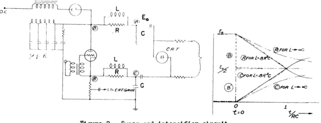
The circuit employe to develop linear sweep speeds of 50-100 in./Lsec is shown in ig. 2. With L = 0.8 R 2, the voltages of opposite sign at 0 and will be linear functions within 5 per cent from t = 0 to t = RO. The value of the time constant RC is
Figure 2. Sweep and intensifier circuit.
determined by the sweep speed required, the voltage sensitivity of the cathode-ra1 tube, and the supply voltage Eo . The voltage at @ is a pulse of amplitude equal to which
is coincident with the start of the sweep so that an appropriate portion may be used to gate the electron beam during the sweep. This pulse is applied to the cathode-ray tube grid and drives it arlmost to zero bias to obtain the maximum light output from the trace on the screen. After each sweep the circuit is recharged through the resonant choke and hold-off diode shown at the upper left. Linear sweeps from 0.1 to 100 in./.sec have been gener-ated with this circuit. Repetitive sweeps to 2000 per second (or higher) as wall as single
sweeps can be obtained.-
-To synchronize the sweep and the voltage transient being studied, two trigger voltages are needed which are free of time Jitter with respect to one another. In the
-2-/
experimental model of the synchroscope the phasing of these two trigger pulses was accom-plished at low level. After being phased these two pulses triggered two independent,biased blocking oscillators, one to supply a voltage pulse to the sweep thyratron and the other
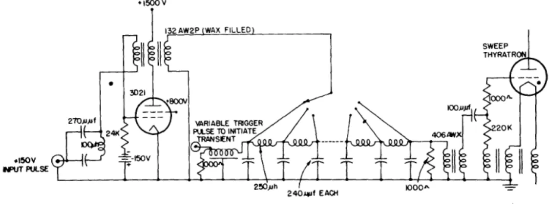
to supply an output trigger pulse to initiate the transient. It was found necessary to reduce the time itter in this scheme and after testing several other methods we decided to use a one-pulse source and do the phasing at high level by means of a tapped delay net-work. Figure 3 shows a 1500-volt biased blocking oscillator which may be run repetitively or used for a single pulse. The output of the transformer is fed into a lumped constant
1500 V
4150V NIUT PULSE
Figure 3. Sweep-phasing circuit.
delay network which has a 0.25-.sec delay per section. The pulse coming out of the right end triggers the thyratron in the sweep circuit. The pulse reaching the left end is fed into a continuously wound delay line having a total delay of 0.8 sec. The sliding contact on the continuously wound line, together with the switch on the lumped network, allow the two pulses to be continuously varied 5 sec with respect to one another. High level phasing eliminates the difficulties of bias ripple, heater pickup, etc., which are present in electronic phasing schemes. With the circuit shown in Fig. 3 there is no observable time itter between the sweep and the synchroscope output trigger pulse on a 75-in./$sec sweep, if d-c heater power is used on the sweep thyratron. For a-c thyratron heater power there is a small time variation,due to heater or cathode conditions,which amounts to about 1 or 2 x 10'9 seconds.
-2 M-eigm picture} of the completed oscilloscope are-shown in Figs. 13 andmif-4agad a complete circuit dAagriaa ---isa-dS w -ig. . Photographic records are obtained on 35-mm Eastman Orthochromatic film No. 5211 by means of an fl.5 coated lens. Individual successive traces are obtained by running the film continuously and thus obtaining a record every time the beam is on. (The decay time constant of the screen is about 10 seconds and there is
practically no smearing of the trace for the film speed needed to record 500 pulses per second). If it is desired to show two or more pulses superimposed, the camera can be momentarily stopped. The sample photographs shown in Figs. 7 through 12 have been enlarged from the 35-mm film; Eastman Kodabromide F5 paper was used to obtain maximum contrast.
This synchroscope may be used to study transient voltages which occur at repeti-tion frequencies up to 2000 per second or it may be used for single transients as well. A
si.x-position internal audio oscillator is provided as well as connections for an external oscillator and/or trigger pulse. There are four sweep speeds: (1)% 1.3 in./lsec,
(2) 7 in./.Jsec, (3) 17 in./4sec, and (4) Z-75 in./4sec. With new film and new cathode-ray tubes, single trace writing speeds up to 300 inches per Asec have been recorded.
3. ExPerimental Pulser
The- need for a. suitable instrument to stud-y the starting-behavior of a pulsed
maetr5tl7ani 'th interaction between Modulator and -- ngnetron constituted thfy original mo-.--ation for the design and cons ytion of the-rat SweepySynchroscope )6cribei above.
n
or'e-r
to demonstrate the ut ty of this synchroscope for observing magnetron startingh4.-r- and- for other a cations involving measurements in the mil!4 microsecond region,
eadecida~L K tmtlIt i. ar er -capab! *of generat i rniigh voltage pug s l ) having a
leading edge whi approaches a ideal step fupntion. Specifiolly, we '&ed to obtain a
pulse having rise time 0.01 Lsec, with X linear rising
edge
and a sharp leading corner an, with rious ripples and other iregularities reduced to a minimum Expediency dic-tated lEe use of a pulser switch which could be synchronized precisely from the synchro-scope trigger pulse and a circuit as near to conventional design as practicable.The basic problem in the design of a pulser for generating a fast rising voltage pulse is to obtain high current immediately after closing the switch, in order to charge th3 output capacitance to full value within the desired time of rise. Intrinsic limita-tions of the switch ae therefore the first consideration. Spark gap switches generally X" "4k'_-v, ,'~ti:.- ~.--.~=b_%~:~_L't~__^~~. f To ~the best of our knc 4ed e, enclosed
triggered gaps cannot be synchronized to less than 0.01 Aisec. Hydrogen thyratrons can be synchronized satisfactorily but have an inherent ionization time of the order of 0.02 sec, Ionization time is also a limitation of spark gap switches but probably to a lesser extent :.n those of the open-air non-synchronous type. The objections to the above types of
-witches, the pulse.shaping limitations of lumped parameter pulse-forming networks (with a
ltrw
-f4 number of sections), and the imperfect response of iron core pulse transformers arenmgiesignificant factors which precluded the use of a line-type pulser for our purpose.
A conventional hard tube pulser output circuit consisting of a high voltage storage capacitor aed a vacuum tube switch (preferably a tetrode) proved to be suitable. The chi3f limitations of this type of switch for obtairing rapidly rising pulses are that the tube cannot be turned on instantly with any practically designed driver circuit, and that the late current obtainable from the tube cannot exceed a certain maximum value.
if, as a irst approximation, we assume that the switch can be turned on
instantly to full current, the value of the current required for a given rise time of the ovutput pulse can be estimated from the relation
c +
-- t 2 (1)
G. N. Glasoe and J. V. Lebacqz, "PuJlse Generators", MII' RL Series, Vol. 5, McGraw-Hill, 1947.
where 0 = the output shunt capacitance (including that of the load) R the load resistance
V = the maximum pulse voltage across the load t = the time of rise.
For example, with reduced to a minimum of say 30 If and R 1000 ohms, the current required for a rise time of 0.01 lisec and maximum voltage of 12 kv is approximately
-12 3 3
I
30 x 10
-x 12 x 10 +12 x 10
10-8 2 x 10³
Z42 amp.
The rate of build-up of plate current, however, depends directly upon the rate of. rise of grid voltage which in turn is determined by the instantaneous power delivered from the driver circuit to the grid input conductance and susceptance of the switch tube. During the positive swing of grid voltage the grid current may become excessive, thus requiring a driving voltage source with very low internal impedance to maintain a rapid rise of grid voltage. In a practical circuit the time required for the plate current to build up may be comparable to the rise time desired for the load voltage pulse. Hence, the actual current required in the output circuit to give a specified time of rise is greater than the value indicated by Eq. (1), the correction factor depending upon the characteristics of the driver and the equivalent input circuit of the vacuum tube switch.
Because of this high current requirement and other considerations we decided to build a hard-tube pulser, using several 5D21 tubes in parallel for the pulser switch. With the 5D211s biased considerably beyond cut-off only a small fraction of the driver pulse amplitude is effective in producing positive grid swing on that part of the eg-4p
characteristic hich corresponds to the steep rise of plate current (i.e. where
-9e is high), hence the total time of rise of the driver pulse may be appreciably greater than the rise time of the output pulse to the load.
For our driver circuit, we therefore decided to use a line-type pulser circuit with a 3045 hydrogen thyratron switch. To avoid the use of a pulse transformer a positive pulse was obtained from a 1000-ohm resistor connected between ground and the thyratron cathode which was capacity coupled to the 5D21 grids. The choice of optimum number of output switch tubes depends upon several factors;
(1) For these short times, the instantaneous current needed to charge the distributed capacity of the load is more than one tube can supply.
(2)
Adding more tubes to obtain more output current necessarily increases the loading of the driver by the grid input circuit of the 5D21's.(3) The exact nature of the e -ip curves for these short pulses is not known and one can only extrapolate from data obtained with longer pulses.
(4) The variation of thyratron impedance as a function of time is not known accurately, and most reasonable assumptions add a non-linear element to the circuit problem.
It is difficult to establish criteria for determining experimentally the optimum number of switch tubes. For example, a very rapidly rising pulse can be obtained with two or three tubes when the grid drive is excessive. The leading corner of the pulse is not
-square, however, but has a spike of about 10-20 per cent amplitude and several millimicro-seconds' duration. If a flat top pulse is desired, the grid drive must be reduced, and a slower rising pulse results. Depending on the particular shape desired, the optimum number of tubes is somewhere between two and six.
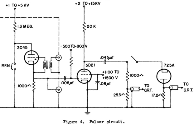
After some preliminary tests with one and two 5D21 tubes on a breadboard model, the circuit shown in Pig. 4 seemed satisfactory, and we decided to construct a large unit with provision to use a maximum of eight 5D21lu in parallel, with a single 3045 driver. It should be pointed out that the various circuit constants indicated in the figure are not necessarily considered to be optimum values. We did not pursue analysis and experi-mentation with the circuit more than was necessary to meet our design objectives, and we were not particularly concerned with economy in power and other engineering refinements which are of secondary importance in a temporary laboratory unit.
TO C.R.T.
Figure 4. Pulser circuit.
The driver is enclosed in a separate copper housing to insure adequate shielding against "pick-up" in the viewing system. Several pulse-forming networks were tried. For long pulses best results were obtained with a length of Federal Telephone and Radio cable RG71/U with a small capacitance connected in parallel with the cable output. For very
short (0,01 sec) pulses we used a capacitance of 100-500 ilf connected in series with a parallel L-R corrective network2 .
Inductance of connecting leads is minimized by the symmetrical arrangement
2. 0. T. Fundingsland and G. J. Wheeler, "Constant Current Circuits", Electronics, 19, pp. 130-133, November 1946.
illustrated in the sketch of ig. 5. The control grids of the 5D21 tubes are connected through individual small resistors to a common "drive" ring. The screen grids are like-wise connected to a common ring and a mica capacitor bypasses each screen to cathode as close to the tube as possible. The plates are all connected to a single conductor which supports the output high voltage capacitor.
D
Figure 5. Pulse generator and load.
The resistance load consists of two 500-ohm WE six-inch tubular carbon-ceramic resistors in series with a 25-ohm BTL coaxial "current-viewing" resistor 3
A similar coaxial current-viewing resistor is connected in series with the ground return of the magnetron. When the magnetron is connected the resistance load also serves as a voltage divider for viewing the magnetron voltage.
The pulses are transmitted to the synchroscope through three-foot lengths of shielded coaxial cable (Federal Telephone and Radio RG71/U). The signal delay in such a cable is comparable to the rise times to be measured. Therefore, in order to avoid unde-sirable reflections, it was necessary to match closely the characteristic impedance of the cable, by means of a shunt resistance at the cathode-ray tube. The cable impedance
measured under pulse conditions was found to be 95 1 ohms.
4. Experimental Results
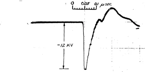
Figure 6 shows a 15-kv pulse obtained with two lD21 tubes operating into a 1000-ohm resistance load. This pulse was viewed on aModel 5 schroscope which had been modified to produce a sweep speed of about 9 in./Lsec. The rise time appears to be less
than 0.005 tsec (measured from 10 per cent to 90 per cent amplitude) and the duration at 90 per cent amplitude is about 0.01 sec. The pulse repetition frequency was 2000 per second. This photograph, however, may not be a true representation of the actual pulse
- O AM 58 Of sac~0
Figure 6. Voltage pulse on 1000-ohm load (leading edge retraced because of low intensity of trace on Model 5 synchroscope).
because we were crowding the upper frequency limit for which low voltage cathode-ray tubes are considered satisfactory. For example, there may have been high frequency oscillations or other irregularities on the actual pulse which were smoothed out in this presentation. Furthermore, the coupling between signal plates and sweep plates on the cathode-ray tube may be sufficient to affect the apparent rate of rise of the pulse even though no gross
"cross talk" involving backward motion of the sweep is obvious.
i
A 725A magnetron (3-cm band) was connected in parallel with the resistance load without otherwise changing the circuit or the operating voltages. The added capacitance of the magnetron and its filament transformer caused some decrease in the voltage rate-of-rise, but the magnetron failed to "fire"; i.e. no conduction current flowed and no r-f output radiation was detectable. Apparently the magnetron behaved only as a capacitance. The only observable current was proportional to the rate-of-rise of applied voltage and when the amplitude of the applied voltage was varied the current did not change in
accord-ance with the dynamic impedaccord-ance characteristic for normal, conduction current during
oscillation. Even with appreciably higher voltage than is normally applied to the tube it was necessary to increase the pulse duration to more than 0.02 "sec at 90 per cent
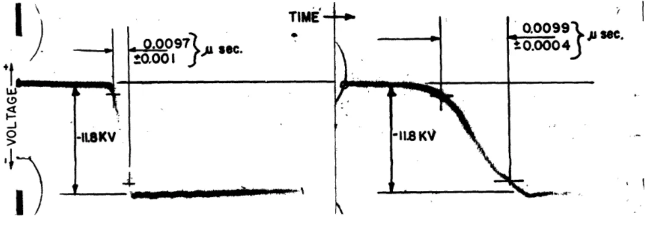
amplitude before a true conduction current appeared and r-f radiation was detectable. The remaining photographs (Figs. 7 through 12) were obtained with the fast sweep synchroscope. The pulser was adjusted to produce pulses of longer duration to insure normal magnetron operation. Figure 7 shows the voltage pulse with the resistance load
only, on both slow and fast sweeps. The pulse repetition frequency was 60 per second.
Figure 7. Voltage pulse on 1000-olm load.
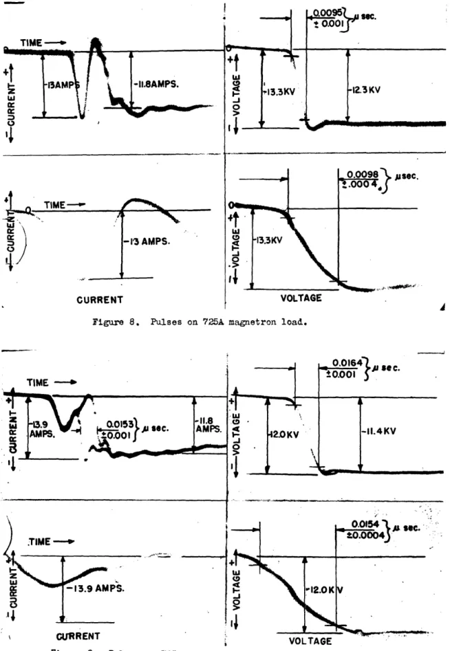
Figure 8 shows corresponding magnetron current and voltage pulses with the same circuit condition. The amplitudes and rise times are indicated on the photographs. Measurements were made from full size prints with the aid of a drafting machine.
Reducing the grid drive effected a slower rising pulse, and induced the magne-tron instability illustrated in Fig. 9. This instability does not appear to be mode Jumping, because the final amplitudes of voltage and current are the same on all pulses. However, it is clear that the main build-up of conduction current occurs at two distinct times on different cycles, with reference to the applied voltage pulse. The lower left photograph of this figure gives a much better resolution of the fine stricture in the region where the current differs on different cycles. Small variations in the leading corner of the voltage pulse are also apparent. Other forms of magnetron instability were observed when the circuit conditions were varied over a wider range.
-9-__11_1_
1 _ _ II
I
I
Figure 8. Pulses on 725A magnetron load.
ig-e VVL I Ae
Figure 9. Pulses on 725A magnetron load with reduced rid drive.
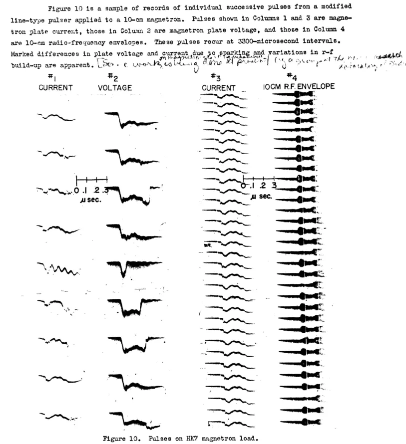
Figure 10 is a sample of records of individual successive pulses from a modified line-type pulser applied to a 10-cm magnetron. Pulses shown in Columns 1 and 3 are magne-tron plate current, those in Column 2 are magnemagne-tron plate voltage, and those in Column 4 are 10-m radio-frequency envelopes. These pulses recur at 3300-microsecond intervals.
Marked differences in plate voltage and current due o pakjngand variations in r-f
build-up are
apparent.
pL•-
J
>i
'at I;1
2
3
VOLTAGE
CURRENT -- -4·"' °--' ~Im ...,--~ .- ' --- St."~"I - - -vsv---1-
2 -
'
-'
0.,)
.1 .2 .'
A sec.
\ A A -A 14Flr ad# - Ir Figure 10. Pulses on HK IOCM R.F. ENVELOPE---. 4t,.,e~-
d
,,_ _ '"-~ sec.'_.
_. an~ __-~im
| { _ _ ^0- 1.2rrE~ - lF.,.: a'",u
sec.
^,.llIj~
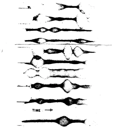
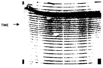
^~-r~t · _ _t -, 1_11~ de __4,.l~n - _ __ magnetron load.Figure 11 shows how the output of a 30-Mc/sec amplifier is affected by random
noise generated in the first stage. The 30-Mc/sec equipment was supplied by G. E. Dvall r ~/aL
t L-IsA
-11-CURRENT
amplifier is in constant operation and the sweep was run at a 60-cycle/sec repetition frequency. *1, Uaff
{' e
n
_
-'
''v'~~~~~~~~~~~s~i
Is itrr L, f~~~~~~0~
iTIME ;
Figure 11. Output of a 30-Mc/sec amplifier modulated by random noise,
This oscilloscope can also be used to study repetitive transients which occur at irregular intervals. Figure 12 shows several sweeps on which no signal appears and only two where the transient happened to occur during the sweep interval. These pictures were obtained from a capacitor which was discharged by a mechanical switch into a resist-. ance load. The oscilloscope sweep and mechanical switch were run from the same 6
00-cycle source but the mechanical switch had an inherent time itter of * 2 sec.
5. Conclusion
The photographs of voltage transients presented here serve as an indication of some of the types of problems which can be studied with the aid of the Fast Sweep
Synchroscope. While the primary objective in the design of the synchroscope was to -12-ICo----· -.11 N,~
t
-rr~~__~~~
__ -~~~rr~
Ilcu o; - --a
TIME
-, . .,--
I
. A i, ... ,
Figure 12. Non-synchronous pulses (condenser discharged by a mechanical switch)
provide a method of recording high speed voltage transients such as those encountered in radar transmitters, an attempt has been made to make this instrument as flexible as possible and already several applications outside of the original field have been made. Provisionsfor direct access to the cathode-ray tube deflecting plates and control grids make possible a wide variety of applications where sweep voltages other than those already available might be used.
In their present form, the synchroscopes show some trace defocussing at sweep repetition frequencies above 2000 per second. This difficulty can probably be eliminated by readjusting time constants of circuits associated with the control grid. There is a
small amount of vertical centering modulation (0.01 to 0.03 in.) at 60 cycles whose source we have been unable to determine.
Although the calculated transit time is small enough to give a 95 per cent response to a 1000-Hc signal, we have not tested the synchroscope to its limit of time
resolution in pulse measurements because of the inherent limitations of pulse generators and auxillary pulse-viewing equipment. Specifically no video amplifier has yet been designed with a 1000-Mc bandwidth for amplifying low voltage signals, and in order to
struct high voltage pulse attenuators with adequate frequency response (balanced time con-stants), it would be necessary to design special high voltage resistors and capacitors which have small physical size and whose distributed inductance and capacitance are made negligibly small. Other considerations include the viewing cable frequency characteristics
and the impedance-matching problem. Our experiments have demonstrated satisfactory perform-ance of the Fast Sweep Synchroscope within the limitations of the auxiliary apparatus
described in this report and conventional pulse-viewing systems.
The assistance of Mr. L. A. Hartis in the development of the sweep-phasing circuit and the work of Messrs. S. R. Ames and A. M. Belinski in the construction and testing of these two synchroscopes are gratefully acknowledged. We also wish to express our appreciation of the friendly interest of many others both inside and out-side the Research Laboratory of Electronics.
-13-L _
FOCUS 8 INTENSITY CONTROLS. CRT FILAMEI TRANSFORME: CATHODE RA TUBES. VARIAC FOR -5KV SUPPLY. PHASE) FIN -ADJ JCOARS INTERNAL AUDK OSCILLATOR.
-SKINAL INPUT TRACE
CENTFRINC. rt¥Xc HIGH VOLTAGE CONTACTOR. MAIN POWER SWITCH. MONEL BRAID 8
D C VOLTAGE CONTROL FOR SILVER PLATE
SIGNAL CALIBRATION. FOR SHIELDING.
/SWEEP LENGTH. SWEEP SPEED.
SELF SYNCHRONOUS TRIGGER INPUT. EXTERNAL AUDI( OSCILLATOR a I IlWIL-tK INU I IIT'DIMI i'1D EXTERNAL SELECTO. TR INTENSITY . TRACE FOCUS. SCREEN ILLUMINATION CONTROL. _
MAIN LINE SWITCH. -5KV SUPPLY METER SWITCH AND FUSE.
*1500VOLT REGULATED
SUPPLY FOR SWEEP
-CIRCUIT.
BLOWER SWITCH.
-- +20KV SUPPLY METER.
SWITCH, FUSE.
-SIGNAL INPUT TO
VER-TICAL DEFLECTING PLATES OF C.R.T.,S.
-SWEEP VOLTAGE CHECK(
POINTS.
-DIRECT CONNECTION
TO DEFLECTING PLATE. -20 AMP LINE FUSES.
-POWER INPUT IIOV
12A I 60 .
-CONVENIENCE OUTLETS
AND SWITCH. VOLTAGE AND CURRENT
-METERS FOR 1500 V SWEEP SUPPLY.
Fast Sweep Synchroscope, front view.
-14-Figure 13.
-CRT POST DEFLECTION ACCELERATOR RINGS cRWAFPD CHACSISI +1500VOLT INPUT.- --POWER INPUTOV 2A bVU IN&'. RAY TUBE (CRT) 3 PLATE FOR )IVIDER AND CONDENSER. AMENT TRANS-S IPPLY RECTIFIER. LTER CONDENSER. LEEDER AND MULTIPLIER. RFACES BETWEEN FRAME AND PLATES ARE BRAID BETWEEN .S REDUCES ANCES INSIDE OF E TO EXTERNAL SUPPLY DIVIDER. UPPLY DIVIDER. SUPPLY TRANSFORM-RECTIFIER TUBES. _- FILTER CONDENSER +20 KV SUPPLY
TRANSFORM-Bast Sweep Synchroscope, top and rear views.
REAH Vlt w Figure 14.
-15-I -15-I_
C_1 I
__·
II bU'V W ERI
I
I
I-C' Itli
(i
-I
C) _ _ __D1 _ 1 - 2 bI ;Ia I It >> l ouA0
i
I
I
I
I
I
I
I
I
I
I
I i
I 1
lI
i0
I
-II
I h Ir¼ OD 0 P'b ' t r) jR I '4% ' at-80o.o
Il---ll·l----l-*·--C--·111_11111·--_-·-N m i_o 1 .-0 )3 I, lK
in
'9 0t~
-I tj 1
ll
a
2
By4:
Ib
I I I I I I Ii
I
I~o·i
; 0 t I I ?vw QD + 0 i:~~~~~~~~4 .aAn
~~~L
xvgI
1-
'~~~~
'
O
; t 4 I NA ts to61F pXI . 11l'rika
it-- -
-lb 4kk
~T§
3 I i lL
II
______j_
.
i____._
I
~~~~~~~~~~~~~~~~~
~ ~ ~ ~
-~-~~~~~~
~
L_'
_Ul r Iw~~~~~
~~
N
oo
ik
oT
L
aI~
_ti <N
s
3et
o
i~~~~~r~v b 1 L a i oS hp i Si W.I 1~~~~~
~~~~~Ci~~~
L~
'
X~~~l
I~
~
0
~ "
t-~
++t.
j
0
C
·