Canada for Buildings 2017
Issued by the
Canadian Commission on Building and Fire Codes
National Research Council of Canada
Natural Resources
Canada
Ressources naturelles
Canada
This publication was made possible with the technical
and financial support of:
ISBN 0-660-25778-5 NR24-24/1-2017E-PDF
NRCC-CONST-56247E
© National Research Council of Canada 2019 Ottawa
World Rights Reserved
Printed in Canada First Printing
2 4 6 8 10 9 7 5 3 1
Aussi disponible en français :
Guide de l’utilisateur du Code national de l’énergie pour les bâtiments – Canada 2017 NRCC-CONST-56247F
ISBN 0-660-25780-8 NR24-24/1-2017F-PDF
Introduction
Commentary on Part 3
Building Envelope
Commentary on Part 4
Lighting
Commentary on Part 5
Heating, Ventilating and Air-conditioning Systems
Commentary on Part 6
Service Water Systems
Commentary on Part 7
Electrical Power Systems and Motors
This is the third edition of the User’s Guide – National Energy Code of Canada for Buildings (NECB). It is intended to complement the NECB 2017 and increase users’ understanding of the Code’s intent and application in the field; as such, it is not to be used as a standalone document. The User’s Guide contains background information, explanatory material and, in some cases, suggested approaches to certain design or compliance matters, but does not contain mandatory requirements and is neither a textbook nor a design guide. The figures it contains are schematic only and the examples are illustrative only: they do not represent design recommendations.
The User’s Guide comprises commentaries on NECB Parts 3 to 8 but does not address each and every Article of the NECB: content was developed for subject areas that were deemed to require further explanation or detailed examples and calculations.
Development
This edition of the User’s Guide is based on the 2015 edition of the User’s Guide. New content was developed for the 2017 edition to address new and updated requirements in the NECB 2017. The User’s Guide was prepared by the Working Group on User’s Guide of the Standing Committee on Energy Efficiency in Buildings. Members of the Working Group include:
D. Bartel (Chair) M. Kelly
R. Cardinal K.W. Lau
H. Hayne M. Roy
The following Codes Canada staff members provided technical and administrative support to the Working Group:
T. Achour P. Tardif
G. Fairthorne R. Ullah
E. Girgis M. Zeghal
M. Mihailovic
Codes Canada owes a special thanks to E. Richman and N. Smirnov for contributing their technical expertise to the development of this User’s Guide.
Overview of the NECB
Objectives
As with the other National Model Construction Codes, the NECB is an objective-based code. Its primary objective is to limit the negative impact of building design and construction on the environment (objective “OE Environment”). Specifically, its provisions aim to limit the probability that buildings will use an excessive amount of energy (sub-objective “OE1.1 excessive use of energy”). Whereas the other Codes address different objectives of safety, health, protection of buildings and accessibility, the NECB’s sole objective is energy efficiency. For example, while the NECB contains requirements related to the power demand of ventilation fan systems, it does not have ventilation flow requirements as these primarily address the health objective and are found in the National Building Code of Canada.
Parts 3 to 8 of Division B: Part 3: Building Envelope Part 4: Lighting
Part 5: Heating, Ventilating and Air-conditioning Systems Part 6: Service Water Systems
Part 7: Electrical Power Systems and Motors
Part 8: Building Energy Performance Compliance Path Compliance
There are three compliance paths in the NECB: the prescriptive path, the trade-off path and the performance path (see the flow chart in NECB Figure A-1.1.2.1. of Division B).
The prescriptive path is a formulaic approach to achieving building design compliance whereby the provisions in NECB Sections 3.2., 4.2., 5.2., 6.2., and 7.2. are applied as stated. For example, to achieve a Code-compliant building envelope using the prescriptive path method, a designer would follow the provisions presented in NECB Section 3.2., Prescriptive Path.
If a builder, designer or building owner wants to use a particular building system or parameter that does not meet the minimum performance level required in the prescriptive path, it may still be possible to demonstrate compliance using the trade-off path provisions in NECB Sections 3.3., 4.3., 5.3., and 6.3. (there are no trade-off options in NECB Part 7). The trade-off path affords some degree of flexibility in the application of the prescriptive requirements, with limitations. One overriding limitation is that each trade-off path is Part-specific: component performance cannot be traded between different building systems or parameters. For example, the HVAC trade-off path cannot be used to trade efficiencies between the HVAC system and the building envelope. But it could be used to trade-off a boiler that does not meet the prescriptive path requirements against air handler units with high-efficiency motors driven by variable frequency drives, as these exceed the minimum performance level of the applicable prescriptive requirements. Other limitations are specific to individual trade-off paths: for example, the lighting trade-off path applies only to interior lighting and not to exterior lighting.
The overriding principle behind the trade-off paths is that the total energy used by the proposed building system or parameter must be less than or equal to that of the reference building system or parameter, which is based on the prescriptive path. The main advantage of the trade-off-path is the flexibility it allows designers over the prescriptive path.
A designer can use any of the simple prescriptive or trade-off options presented in each Part or a combination of simple prescriptive for some building parameters and trade-off for others. The building energy performance compliance path in NECB Part 8 is a whole building approach. The path compares the performance of a proposed building to that of a reference building, i.e., one that follows the prescriptive path. The performance path allows performance losses in one building system or parameter to be offset by performance gains in another. For example, a proposed building with a boiler that is less efficient than required in the prescriptive path could have a building envelope with better thermal performance than required in the prescriptive path. If the total energy consumption of the proposed building is less than or equal to that of the reference building, the design is considered NECB-compliant. The performance path cannot be used to test the compliance of individual building systems or parameters; if chosen, it must be used for the compliance of all building systems and parameters.
Due to the complexity of the calculations involved (e.g., hourly calculations) in applying the performance path provisions, computer simulations are typically used to demonstrate compliance. Referenced Standards
Unless otherwise specified, the applicable editions of the standards referenced in this User’s Guide are the editions referenced in the NECB 2017, including any updates to those standards published by Codes Canada.
insight into the Code development process, the structure of the NECB, and the relationship between its Divisions, as well as a deeper understanding of the objective-based approach and how it opens the door to innovation.
Building Envelope
Scope (Article 3.1.1.1.)
1. NECB Part 3 addresses the transfer of heat and air through the building envelope and establishes
the minimum acceptable measures for the adequate thermal performance of the building envelope materials, components and assemblies. The NECB defines the building envelope as the collection of components that separate conditioned space (including semi-heated space) from unconditioned space, the exterior air or the ground, or that separate interior spaces intended to be conditioned to temperatures differing by more than 10°C at design conditions. The building envelope, which includes the walls, roofs, floors, fenestration and doors of a building, plays an important role in determining the amount of energy required to accommodate the occupancy of a building. The transfer of heat and air through the building envelope is an important consideration for energy efficiency.
Application (Article 3.1.1.2.)
2. The requirements in NECB Part 3 apply to all new buildings and additions that are equipped with
space-conditioning systems or have provisions for the future installation of such systems and that have a heating and/or cooling system output capacity that is equal to or greater than 10 W/m2of
floor surface area. The requirements do not apply to unconditioned spaces or to farm buildings.
Compliance (Article 3.1.1.3.)
3. Compliance with NECB Part 3 can be achieved by following one of three paths: the prescriptive
path, the trade-off path, or the performance path. The three paths allow designers the flexibility to either strictly apply the NECB prescriptive requirements, use trade-offs to meet the requirements, or apply a more detailed whole building energy performance approach to their design. The flow chart in NECB Figure A-3.1.1.3.(1) shows the available options for building envelope compliance. The three compliance paths are explained in Paragraphs 42 to 68.
Thermal Characteristics of Building Assemblies (Article 3.1.1.5.)
4. The thermal characteristics of building envelope materials are typically determined through testing
in accordance with relevant material standards, many of which are referenced in the National Building Code of Canada 2015 (NBC). Where no standard exists for a particular material, or where a particular standard does not address the thermal characteristics of a material, this data can be obtained through testing in accordance with ASTM C 177, “Steady-State Heat Flux Measurements and Thermal Transmission Properties by Means of the Guarded-Hot-Plate Apparatus,” or ASTM C 518, “Steady-State Thermal Transmission Properties by Means of the Heat Flow Meter Apparatus.” Manufacturers often reference these standards in their material literature along with the thermal properties of their materials.
5. An understanding of heat transfer fundamentals, including the concepts of thermal conductivity
and thermal resistance, is essential to the design, selection and evaluation of building envelope assemblies that comply with the NECB Part 3 requirements.
6. Heat spontaneously travels from an area of high temperature to an area of low temperature in an
attempt to reach thermal equilibrium. Heat flow in building envelope assemblies occurs through a combination of convection, radiation and conduction. The NECB requirements address conduction. Heat transfer in building envelope assemblies can be minimized by using a combination of building components that resist heat flow and by controlling air leakage.
7. The overall thermal transmittance (U-value) is a measure of the rate, in W/(m2∙K), at which heat is
transferred through a building assembly whose two faces are simultaneously exposed to different temperatures. The U-value represents the amount of heat transferred through a unit area, in a unit of time, induced under steady-state conditions by a unit temperature difference between the environments on its two faces. The U-value reflects the capacity of all elements to transfer heat through the thickness of the assembly, including through air films. The effective thermal resistance (RSI value, in metric units) is the reciprocal of the overall thermal transmittance, as shown in the following equation, and is measured in (m2∙K)/W:
where
RSI = effective thermal resistance, in (m2∙K)/W, and
U = overall thermal transmittance, in W/(m2∙K).
8. Ideally, building envelope assemblies are selected or designed based on the building type, use, and
location since they must be appropriate for both internal and external loads. They can drastically improve a building’s overall performance and energy efficiency. Building envelope assemblies do not require the direct use of energy and have a significant impact on thermal comfort and building heating and cooling loads. The consideration of outdoor conditions to which a building envelope assembly will be subjected is one of the first steps in the design and selection process.
9. A reasonable estimate of annual heating energy consumption can be obtained from the demand
and the heating degree-days (HDD) of the building location. The NECB Part 3 requirements for the maximum U-value of building envelope assemblies are related to the applicable HDD category for the building location. An HDD value is the sum of the differences between the mean temperature for the day and 18°C for every day in the year when the mean temperature is below 18°C. Values for selected locations in Canada are listed in NECB Table C-1. For locations not listed, HDD values may be obtained from Environment and Climate Change Canada (www.ec.gc.ca).
10. The NECB uses the following six HDD categories, known as Zones:
Table 3-1
Heating Degree-Day Zones
Zone Heating Degree-Days of Building Location,
Celsius Degree-Days 4 < 3000 5 3000 to 3999 6 4000 to 4999 7A 5000 to 5999 7B 6000 to 6999 8 ≥ 7000
11. In general, the ascending numbered Zones designate southern to northern areas of Canada. The
Zones are based on the climate zones found in ANSI/ASHRAE/IES 90.1, “Energy Standard for Buildings Except Low-Rise Residential Buildings.” Canada has no locations falling under Zones 1 to 3; Zone 4 is the mildest zone in Canada (Victoria, British Columbia, is an example of a Zone 4 location), while Zone 8 is the coldest (Yellowknife, Northwest Territories, is an example of a Zone 8 location). In the NECB Part 3 requirements, the maximum overall thermal transmittance of building assemblies decreases (i.e., becomes more stringent) as the HDD value increases. For example, the maximum overall thermal transmittance for roofs in Zone 4 is 0.193 W/(m2∙K) compared to
Accounting for Thermal Bridging Elements (Sentence 3.1.1.5.(5) and
Article 3.1.1.7.)
12. In the 2011 and 2015 editions of the NECB, thermal bridging of only a few building elements was
factored into the calculation of the overall thermal transmittance of building envelope assemblies. The surface areas of these elements were considered as heat transfer paths. This approach
disregarded other heat transfer paths, such as window-to-wall transitions, which have no definable area but are a source of significant heat transfer. Not accounting for all occurrences of thermal bridging across the building envelope meant that opaque building assemblies could have greater actual overall thermal transmittance values than those required by the NECB—possibly two or more times higher than the values determined from calculation methods that ignore the cumulative effect of thermal bridging.
13. The consequences of not appropriately accounting for the impact of all thermal bridges include
higher energy use than expected based on the results of energy use analyses carried out with inaccurate input values, missed opportunities to achieve lower energy costs, and wasted resources (e.g., when a high level of thermal insulation is called for in a design and the assumed benefit is not achieved due to thermal bridging).
14. The 2017 edition of the NECB requires that thermal bridging of many more elements be accounted
for, which should motivate designers to mitigate its effects through improved construction details. Current methods of determining overall thermal transmittance produce more accurate values by using linear and point transmittance data to account for thermal bridging.
15. See the 2016 edition of the “Building Envelope Thermal Bridging Guide” for an example on how
to determine the thermal characteristics of a building envelope assembly using the ISO 14683 standard for a generic building interface or using both a clear field assembly and the Guide’s linear and point transmittance catalogue.
Calculation of Overall Thermal Transmittance (Article 3.1.1.7.)
16. A thorough understanding of the methods used in determining or calculating the U-value of opaque
building envelope assemblies is important for demonstrating compliance with NECB Part 3.
17. NECB Sentence 3.1.1.7.(4) provides a credit for any unconditioned space protecting a component
of the building envelope. The enclosure’s assumed overall thermal transmittance (U-value) of 6.25 W/(m2∙K) allows the effective thermal resistance (RSI value) for the protected areas
of above-ground opaque building envelope assemblies to be reduced by 0.16 (m2∙K)/W, as
demonstrated in Example 3-1. The credit provided in NECB Sentence 3.1.1.7.(4) does not apply to vented spaces because such spaces are considered to be part of the exterior space (see NECB Note A-3.1.1.7.(5)).
Example 3-1 – Maximum Overall Thermal Transmittance of an Exterior Above-Ground Opaque Wall Protected by an Enclosed Unconditioned Space
In Regina, Saskatchewan, an exterior above-ground opaque wall is protected by an enclosed unconditioned space. According to NECB Table C-1, Regina has an HDD of 5600, which corresponds to Zone 7A (see Table 3-1 in Paragraph 10). The maximum overall thermal transmittance (U-value) for above-ground opaque walls in Zone 7A is 0.21 W/(m2∙K) according to NECB Table 3.2.2.2. To
apply the credit of 6.25 W/(m2∙K) provided in NECB Sentence 3.1.1.7.(4), both the credit and the
maximum overall thermal transmittance must be converted to RSI values as follows:
The adjusted RSI value for the protected wall is then calculated as follows:
To obtain the adjusted maximum overall thermal transmittance (U-value) for the protected wall, the adjusted RSI value is converted to a U-value as follows:
Therefore, the adjusted maximum overall thermal transmittance for the protected wall is 0.217 W/(m2∙K).
18. Building envelope assemblies are typically composed of several components, which may include
building materials, thermal insulation, and air spaces (or air cavities). Each component has its own ability to resist heat flow. Since heat transfer occurs across the entire assembly, the thermal resistance (RSI value) of each component, including any air space, is used to calculate the U-value of the assembly. Air films on the interior and exterior surfaces of the assembly also have an impact on heat transfer and must be considered in the calculation of the U-value. The thermal resistance of these air films is affected by their position in the assembly, the direction of heat transfer, the temperature of the surface and the air, the difference between the temperature of the surface and that of the surroundings, and the surface’s long-wave emittance.
19. In cases where the U-value of a building envelope assembly has not already been determined
through computer analysis and/or laboratory tests, it can be calculated using the simplified calculation procedures described in the “ASHRAE Handbook – Fundamentals.” The method of calculation used depends on the type of assembly in question. Three methods of calculating the U-value of a building envelope assembly are described below:
• Isothermal Planes Method: method for assemblies with continuous components and no thermal bridging effects. Refer to Figure 3-1 in Paragraph 27.
• Isothermal Planes and Parallel Path Method: method that applies to wood-frame assemblies where heat flow through the thermal bridge is parallel to heat flow through the insulation and the temperature at each plane in the assembly is constant. This method differs from the Isothermal Planes Method, which applies only to assemblies with continuous components. Refer to Figure 3-2 in Paragraph 32.
• Metal-frame Assembly Method: method that applies to metal-frame assemblies where an effective value for the insulation/framing portion is used and the Isothermal Planes Method is used for continuous material layers. Refer to Figure 3-3 in Paragraph 35.
20. To calculate the U-value of a building assembly using the three methods described in Paragraph 19,
the following information is required:
• the RSI values of air spaces that form part of the assembly (see Paragraph 22),
• the RSI values of indoor and outdoor air film resistances, as applicable (see Paragraph 23), and • the type, size and spacing of repetitive framing members that form part of the assembly and
have a thermal bridging effect on the assembly (see Paragraph 24).
21. Typical RSI values for some common insulation and building envelope materials are listed in
Tables 3-4 to 3-8 (see Paragraph 70). RSI values can also be obtained from material manufacturers and the “ASHRAE Handbook – Fundamentals.”
22. The RSI value of air spaces varies with heat flow direction. Typical RSI values for air spaces are listed
in Table 3-8 (see Paragraph 70) according to the type of assembly (i.e., ceiling, floor or wall) and the thickness of the air space. For air space geometries not shown, data can be sourced from the “ASHRAE Handbook – Fundamentals.”
23. The RSI value of air films also varies with heat flow direction. For exterior air films, the RSI values
depend on wind speed. Typical RSI values for air films are listed in Table 3-8 (see Paragraph 70) according to type (interior or exterior) and location (ceiling, floor or wall). For air film types not shown, data can be sourced from the “ASHRAE Handbook – Fundamentals.”
24. Values for framing percentages for typical wood-frame assemblies are listed in Table 3-9 (see
Paragraph 70) according to assembly type and frame spacing. Values for framing percentages can also be calculated based on actual construction. These values are needed to calculate U-values in the Isothermal Planes and Parallel Path Calculation Method for wood-frame assemblies.
25. For all of the methods described above, the effects of fasteners, brick ties and connectors through
the building envelope components are typically ignored in assemblies with continuous insulation since these components have little effect on U-value. In an uninsulated cavity, the effect of metal wall ties is negligible. In any cavity, the effect of plastic ties is negligible. In some cases, the RSI value of certain building components, such as polyethylene vapour barriers, metal decks, fabric or paper sheeting products, is so low as to be considered negligible, and as such they are assigned an RSI value of zero in the U-value calculations.
U-value Calculation for Building Assemblies with Continuous Insulation – Isothermal Planes Calculation Method
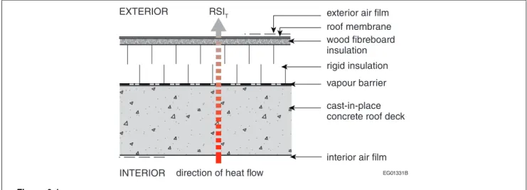
26. Where a building assembly contains only continuous materials, the simplest method of calculating
the U-value can be used, which is the one-dimensional Isothermal Planes Calculation Method. It applies, for example, to building assemblies that do not use framing within the insulating portion of the assembly, such as flat roofs or a fully insulated floor slab. The method involves adding together the thermal resistances of each component of the assembly. The reciprocal of this sum is the U-value of the assembly, UT, which is calculated as follows:
where
RSIT = sum of the thermal resistances of the components of the assembly, including interior and
exterior air films, in (m2∙K)/W.
27. Figure 3-1 shows a graphical representation of the Isothermal Planes Method heat flow calculation
EG01331B cast-in-place concrete roof deck vapour barrier rigid insulation roof membrane wood fibreboard insulation RSIT
direction of heat flow
interior air film exterior air film EXTERIOR
INTERIOR Figure 3-1
Graphical representation of U-value calculation using the Isothermal Planes Calculation Method
28. Examples of U-value calculations using the Isothermal Planes Calculation Method are presented in
Examples 3-2 to 3-5.
Example 3-2 – Floor: Insulated Concrete Slab-on-Grade
Figure A shows an insulated concrete slab-on-grade with radiant heating.
EG01336B 152-mm gravel base
vapour barrier
64-mm expanded polystyrene (EPS) insulation (Type 2) 100-mm cast-in-place concrete with radiant heating interior air film
INTERIOR
EXTERIOR
RSIT
direction of heat flow
Figure A
Insulated concrete slab-on-grade (section view)
Since the assembly contains only continuous materials, the Isothermal Planes Calculation Method is used to calculate the overall thermal transmittance. The RSI values of all the assembly’s components can be obtained from Tables 3-4 to 3-8 (see Paragraph 70), taking into account the thickness of the materials and the RSI value of the interior air film. The overall thermal transmittance, UT, can be
calculated as follows:
Assembly Components RSI, (m2·K)/W
Interior air film 0.16
100-mm cast-in-place concrete slab (normal density aggregate) 0.04
Vapour barrier 0.00
64-mm EPS insulation (Type 2) 1.79
RSIT 1.99
Example 3-3 – Roof: Flat Roof (4-ply built-up roofing (BUR) and steel deck) Figure A shows a roofing assembly with 4-ply BUR and a steel deck.
EG01337B 25-mm wood
fibreboard insulation 127-mm polyisocyanurate insulation
4-ply roof membrane
vapour barrier steel deck interior air film exterior air film EXTERIOR
INTERIOR
RSIT
direction of heat flow Figure A
Flat roof – 4-ply BUR and steel deck (section view)
Since the assembly contains only continuous materials and the metal decking does not penetrate the thermal insulation, the Isothermal Planes Calculation Method is used to calculate the overall thermal transmittance. The RSI values of all the assembly’s components can be obtained from Tables 3-4 to 3-8 (see Paragraph 70), taking into account the thickness of the materials and the RSI values of the interior and exterior air films. If the roof insulation is tapered to allow roof drainage, the average insulation thickness would be taken into account in the calculations. The overall thermal transmittance, UT, can be calculated as follows:
Assembly Components RSI, (m2·K)/W
Exterior air film 0.03
4-ply roof membrane (built-up roofing, 10 mm) 0.06
25-mm wood fibreboard insulation (insulating fibreboard) 0.40
127-mm polyisocyanurate insulation 4.85
Vapour barrier 0.00
Steel deck 0.00
Interior air film 0.11
RSIT 5.45
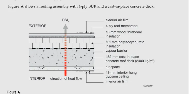
Example 3-4 – Roof: Flat Roof (4-ply BUR and cast-in-place concrete deck)
Figure A shows a roofing assembly with 4-ply BUR and a cast-in-place concrete deck.
EG01338B 13-mm interior hung
gypsum ceiling
13-mm wood fibreboard insulation
interior air film INTERIOR vapour barrier air space 101-mm polyisocyanurate insulation 152-mm cast-in-place
concrete roof deck (2400 kg/m3) 4-ply roof membrane
exterior air film EXTERIOR
RSIT
direction of heat flow
Figure A
Flat roof – 4-ply BUR and concrete deck (section view)
Since the assembly contains only continuous materials, the Isothermal Planes Calculation Method is used to calculate the overall thermal transmittance. The RSI values of all the assembly’s components can be obtained from Tables 3-4 to 3-8 (see Paragraph 70), taking into account the thickness of the materials and the RSI values of the interior and exterior air films. The overall thermal transmittance, UT, can be calculated as follows:
Assembly Components RSI, (m2·K)/W
Exterior air film 0.03
4-ply roof membrane (built-up roofing, 10 mm) 0.06
13-mm wood fibreboard insulation (insulating fibreboard) 0.21
101-mm polyisocyanurate insulation (permeably faced) 3.86
Vapour barrier 0.00
152-mm cast-in-place concrete roof deck 0.06
38-mm air space 0.16
13-mm gypsum board 0.08
Interior air film 0.11
RSIT 4.57
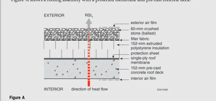
Example 3-5 – Roof: Flat Roof (protected membrane and pre-cast concrete deck)
Figure A shows a roofing assembly with a protected membrane and pre-cast concrete deck.
EG01346B 60-mm crushed stone (ballast) filter fabric exterior air film
152-mm extruded polystyrene insulation
152-mm pre-cast concrete roof deck interior air film protection sheet single-ply roof membrane
INTERIOR
EXTERIOR RSIT
direction of heat flow Figure A
Flat roof – single-ply membrane and concrete deck (section view)
Since the assembly contains only continuous materials, the Isothermal Planes Calculation Method is used to calculate the overall thermal transmittance. The RSI values of all the assembly’s components can be obtained from Tables 3-4 to 3-8 (see Paragraph 70), taking into account the thickness of the materials and the RSI values of the interior and exterior air films. The overall thermal transmittance, UT, can be calculated as follows:
Assembly Components RSI, (m2·K)/W
Exterior air film 0.03
60-mm crushed stone (ballast) 0.04
Filter fabric 0.00
152-mm extruded polystyrene insulation 5.32
Single-ply roofing membrane 0.00
Protection sheet 0.00
152-mm pre-cast concrete roof deck 0.06
Interior air film 0.11
RSIT 5.56
U-value Calculation for Wood-frame Construction – Isothermal Planes and Parallel Path Calculation Method
29. For building assemblies that use wood-frame construction, the U-value can be calculated using the
Isothermal Planes Method for the continuous material layers and the parallel path method for the framing portion of the assembly. The method involves adding the thermal resistances of each component of the assembly together for the continuous material layers and using the parallel path method to calculate the thermal resistance of the assembly along the line that goes through the framing portion of the assembly, and along the line that goes through the cavity portion of the assembly. For the parallel path method, the values are combined in proportion to the relative areas of the framing and insulation to calculate the effective RSI value.
30. The effective (i.e., overall) thermal resistance, RSIT, using the parallel path method is calculated
as follows:
where
RSIF = thermal resistance of the framing portion of the assembly, and
RSIC = thermal resistance of the cavity portion of the assembly.
31. The values for the framing and cavity percentages can be obtained from Table 3-9 (see Paragraph 70)
or can be calculated based on the actual construction. The reciprocal of RSITis the overall U-value of
the assembly, UT
32. Figure 3-2 shows a graphical representation of the Isothermal Planes and Parallel Path Method heat
flow calculation through a wood-frame wall assembly.
EG01333B gypsum board exterior air film EXTERIOR INTERIOR cladding insulating sheathing wood stud air/vapour barrier RSIC
RSIthrough isothermal planes(1) sheathing
paper cavity insulation
RSIF
direction of heat flow
interior air film
Figure 3-2
Graphical representation of U-value calculation using the Isothermal Planes and Parallel Path Calculation Method Note to Figure 3-2:
(1) All materials are continuous on either side of framed portion.
33. Examples of U-value calculations using the Isothermal Planes and Parallel Path Method are
Example 3-6 – Roof: Attic-Type Wood Truss
Figure A shows an attic-type wood truss assembly.
EG01348B 13-mm gypsum board vapour barrier vented air space
interior air film
bottom chord wood truss 38 x 89 mm@ 610 mm o.c. 89-mm blown cellulose insulation
140-mm blown cellulose insulation
exterior air film
INTERIOR EXTERIOR
RSIT
direction of heat flow
Figure A
Attic-type wood truss (section view)
Since the assembly contains wood framing, the Isothermal Planes and Parallel Path Method is used to calculate the overall thermal transmittance. The RSI values of all the assembly’s components can be obtained from Tables 3-4 to 3-8 (see Paragraph 70), taking into account the thickness of the materials and the RSI values for the interior and exterior air films. The framing percentages can be obtained from Table 3-9 (see Paragraph 70). The overall thermal transmittance, UT, can be
calculated as follows:
Assembly Components RSI, (m2·K)/W
Roof air space (exterior air film) 0.03
Blown cellulose insulation 3.50
% Area Framing % Area Cavity
Framing percentages (wood trusses @ 610 mm o.c.)
11 89
RSIFthrough bottom chord, (m2·K)/W
RSICthrough cavity, (m2·K)/W
Bottom chord (89 mm x 0.0085 RSI/mm) 0.757 −
Blown cellulose insulation − 2.14
1.78
Vapour barrier 0.00
13-mm gypsum board 0.08
Interior air film 0.11
RSIT 5.50
Example 3-7 – Wall: Wood-Frame Wall (brick masonry veneer)
Figure A shows a wood-frame wall with brick masonry veneer.
EG01349B 13-mm gypsum board
100-mm brick masonry veneer 20-mm insulating fibreboard 38-mm air space
sheathing membrane, breather-type vapour barrier
interior air film INTERIOR EXTERIOR
exterior air film batt insulation
38 x 140 mm wood stud @ 610 mm o.c.
RSIT direction of heat flow
Figure A
Wood frame wall – brick masonry veneer (plan view)
Since the assembly contains wood framing, the Isothermal Planes and Parallel Path Method is used to calculate the overall thermal transmittance. The RSI values of all the assembly’s components can be obtained from Tables 3-4 to 3-8 (see Paragraph 70), taking into account the thickness of the materials and the RSI values of the interior and exterior air films. The framing percentages can be obtained from Table 3-9 (see Paragraph 70). The overall thermal transmittance, UT, can be
calculated as follows:
Assembly Components RSI, (m2·K)/W
Exterior air film 0.03
100-mm brick masonry veneer 0.07
38-mm air space(1) 0.18
Sheathing membrane, breather-type 0.00
20-mm insulating fibreboard 0.32
% Area Framing % Area Cavity
Framing percentages (wood studs @ 610 mm o.c.)
20 80
RSIFthrough stud, (m2·K)/W RSICthrough cavity, (m2·K)/W)
Wood studs (140 mm x 0.0085 RSI/mm) 1.19 −
Batt insulation − 4.23
2.80
13-mm gypsum board 0.08
Interior air film 0.12
RSIT 3.60
UT= 1/RSIT 0.278
(1) The air space in this Example’s masonry cladding system with weep holes at its base is considered, in this illustrative calculation
only, to be an enclosed air space as described in the “ASHRAE Handbook – Fundamentals.” The most appropriate means of determining the overall thermal values, whether by calculation or by laboratory testing per NECB Sentence 3.1.1.5.(5), must be carefully considered for each situation.
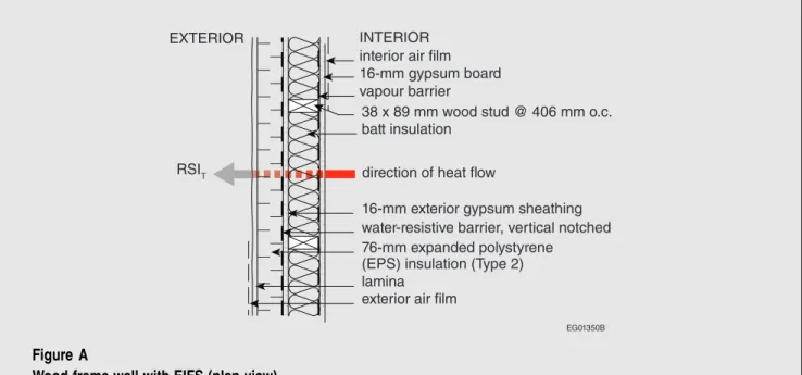
Example 3-8 – Wall: Wood-frame Wall (exterior insulation and finish system)
Figure A shows a wood-frame wall with an exterior insulation and finish system (EIFS).
EG01350B 16-mm gypsum board
16-mm exterior gypsum sheathing water-resistive barrier, vertical notched 76-mm expanded polystyrene (EPS) insulation (Type 2) vapour barrier
interior air film INTERIOR EXTERIOR
batt insulation
lamina exterior air film
38 x 89 mm wood stud @ 406 mm o.c.
RSIT direction of heat flow
Figure A
Wood-frame wall with EIFS (plan view)
Since the assembly contains wood framing, the Isothermal Planes and Parallel Path Method is used to calculate the overall thermal transmittance. The RSI values of all the assembly’s components can be obtained from Tables 3-4 to 3-8 (see Paragraph 70), taking into account the thickness of the materials and the RSI values of the interior and exterior air films. The framing percentages can be obtained from Table 3-9 (see Paragraph 70). The overall thermal transmittance, UT, can be
calculated as follows:
Assembly Components RSI, (m2·K)/W
Exterior air film 0.03
Lamina −
76-mm EPS insulation (Type 2) 2.13
Water-resistive barrier (vertical notched)
0.00 16-mm exterior gypsum
sheathing
0.101
% Area Framing % Area Cavity
Framing percentages (wood studs @ 406 mm o.c.)
23 77
RSIFthrough stud, (m2·K)/W RSICthrough cavity, (m2·K)/W Wood studs (89 mm x 0.0085 RSI/mm) 0.757 − Batt insulation − 2.47 1.62 Vapour barrier − 16-mm gypsum board 0.098
Interior air film 0.12
RSIT 4.10
Example 3-9 – Wall: Wall in Contact with Ground (concrete wall with wood framing) Figure A shows a concrete wall with wood framing in contact with the ground.
EG01351B 200-mm below-grade concrete foundation wall
16-mm gypsum board
ground
dampproofing and drainage layer vapour barrier
interior air film INTERIOR EXTERIOR
batt insulation
moisture protection coating
38 x 140 mm wood stud @ 610 mm o.c.
RSIT direction of heat flow
Figure A
Wall in contact with ground – interior wood framing (plan view)
Since the assembly contains wood framing, the Isothermal Planes and Parallel Path Method is used to calculate the overall thermal transmittance. The RSI values of all the assembly’s components can be obtained from Tables 3-4 to 3-8 (see Paragraph 70), taking into account the thickness of the materials and the RSI values of the interior and exterior air films. The framing percentages can be obtained from Table 3-9 (see Paragraph 70). The overall thermal transmittance, UT, can be
calculated as follows:
Assembly Components RSI, (m2·K)/W
Dampproofing and drainage layer
0.00
200-mm concrete 0.08
Moisture protection coating 0.00
% Area Framing % Area Cavity
Framing percentages (wood studs @ 610 mm o.c.)
13 87
RSIFthrough stud, (m2·K)/W RSICthrough cavity, (m2·K)/W Wood studs (140 mm x 0.0085 RSI/mm) 1.19 − Batt insulation − 4.23 3.18 Vapour barrier 0.00 16-mm gypsum board 0.098
Interior air film 0.12
RSIT 3.48
U-value Calculation for Metal-frame Construction – Variation on the Isothermal Planes Method
34. For building assemblies that use metal-frame construction, a variation on the Isothermal Planes
Method can be used in which the framed portion is treated as a continuous layer since its effective thermal resistance is known. The effective thermal resistance of the insulation/framing is obtained from Tables 3-2 and 3-3 for the framed portion of the assembly and added to the sum of the thermal resistance value of each component of the assembly to obtain the overall thermal resistance of the assembly. The use of Tables 3-2 and 3-3 should be limited to the rated RSI value of insulation shown in the Table and interpolation within those Table values. The Table values should not be extrapolated as an accurate result will not be obtained.
Table 3-2
Effective RSI Values of the Insulation/Framing Layer in Metal-frame Roof and Floor Assemblies (1.2 m on centre)(1)
Rated RSI Value of Insulation Correction Factor Effective Framing/Cavity RSI Value
0.00 1.00 0.00 0.70 0.97 0.68 0.88 0.96 0.85 1.41 0.94 1.32 1.76 0.92 1.62 1.94 0.91 1.76 2.11 0.90 1.90 2.29 0.90 2.06 2.64 0.88 2.32 2.82 0.87 2.45 3.35 0.86 2.88 3.52 0.85 2.99 3.70 0.84 3.11 4.23 0.82 3.46 4.40 0.81 3.57 5.28 0.79 4.17 6.16 0.76 4.68 6.69 0.74 4.95 7.04 0.73 5.14 7.92 0.71 5.63 8.80 0.69 6.07 9.68 0.67 6.49
Table 3-3
Effective RSI Values of the Insulation/Framing Layer in Metal-frame Wall Assemblies(1)
Nominal Depth of Cavity,
mm Actual Depth of Cavity, mm
Rated RSI Value of Air Space or Insulation
Effective Framing/Cavity RSI Value at 406 mm o.c.
Effective Framing/Cavity RSI Value at 610 mm o.c. Empty Cavity, No Insulation
100 89 0.16 0.14 0.16 Insulated Cavity 100 89 1.94 0.97 1.16 100 89 2.29 1.06 1.27 100 89 2.64 1.13 1.37 150 152 3.35 1.25 1.51 150 152 3.70 1.30 1.58 200 203 4.40 1.37 1.69
(1) This Table is reproduced from Table A9.2B of ANSI/ASHRAE/IES 90.1-2010 with permission (©ASHRAE).
35. Figure 3-3 shows a graphical representation of the U-value calculation for metal-frame construction.
EG01332B gypsum board
interior air film INTERIOR EXTERIOR
exterior air film cladding
insulating sheathing air/vapour barrier
effective framing/cavity RSI value steel stud
cavity insulation
RSIT direction of heat flow
sheathing paper
Figure 3-3
Graphical representation of U-value calculation for metal-frame construction
36. An example of a U-value calculation for metal-frame construction assemblies is presented in
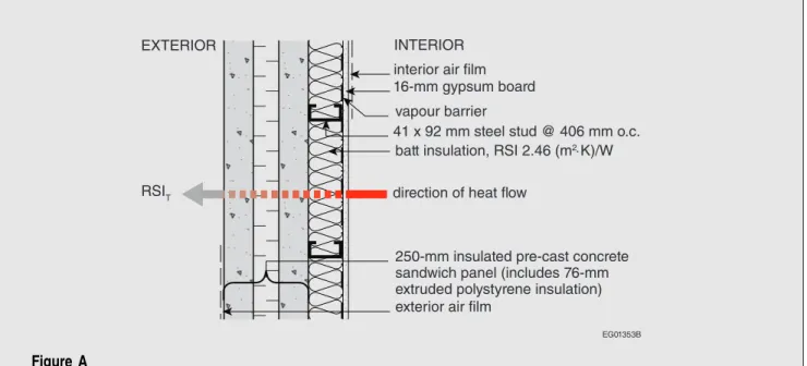
Example 3-10 – Wall: Metal-frame Wall (insulated pre-cast concrete panels)
Figure A shows a metal-frame wall with insulated pre-cast concrete panels.
EG01353B 16-mm gypsum board
250-mm insulated pre-cast concrete sandwich panel (includes 76-mm extruded polystyrene insulation) batt insulation, RSI 2.46 (m2⋅K)/W 41 x 92 mm steel stud @ 406 mm o.c.
vapour barrier interior air film INTERIOR EXTERIOR
exterior air film
RSIT direction of heat flow
Figure A
Metal-frame wall – insulated pre-cast concrete panels (plan view)
Since the assembly contains metal framing, the Isothermal Planes Method for calculating the overall thermal transmittance is used with the effective insulation/framing layer U-values from Tables 3-2 and 3-3 (see Paragraph 32) for the framed portion of the assembly. The RSI value of the assembly’s other components can be obtained from Tables 3-4 to 3-8 (see Paragraph 70), taking into account the thickness of the materials and the RSI values of the interior and exterior air films. The overall thermal transmittance, UT, can be calculated as follows:
Assembly Components RSI, (m2·K)/W
Exterior air film 0.03
250-mm precast concrete sandwich panel (includes 76-mm extruded polystyrene)
2.73 Effective RSI value steel studs/batt insulation interpolated from
Table 3-3, batt = 2.46 (m2·K)/W
1.094
Vapour barrier 0.00
16-mm gypsum board 0.098
Interior air film 0.12
RSIT 4.072
37. Where building assemblies are more complex, such as in metal and glass curtain wall systems, the
thermal bridging that occurs due to mullions and other components must be considered in the determination of the U-value. For complex assemblies, computer analysis and/or laboratory testing will provide greater accuracy in the determination of the U-value.
38. In wood- or metal-frame assemblies, heat transfer across the portion of the assembly that includes
the framing members is greater than through the portion that is insulated (cavity). These framing members reduce the overall thermal efficiency of the assembly and the impact can be substantial since framing materials can account for 20% or more of the surface area of an assembly. This thermal bridging effect depends on the type of assembly, the type of framing material used, and the spacing of the framing member. These factors are considered in the U-value calculations. Values for framing percentages for typical wood assemblies are listed in Table 3-9. Effective insulation/framing RSI values for metal framing are listed in Tables 3-2 and 3-3.
39. Advanced framing is a technique used to reduce the quantity of materials used in wood-frame
construction by engineering each framing element, as opposed to using standard framing details. Not only does it result in lower construction costs, since fewer materials and less labour are required, it also improves the energy efficiency of assemblies. Since fewer framing members are required, the effects of thermal bridging are reduced and therefore the effective thermal resistance of the assembly improves. Advanced framing is an energy-efficient alternative to standard wood-framing methods. Framing percentages associated with advanced wood framing are also listed in Table 3-9.
U-value Calculation for Masonry Block Wall Construction
40. For building assemblies that use concrete masonry units with insulation inserts, hollow or filled
cores, with or without wood- or metal-framing, the U-value of the assembly is calculated using the method that best suits the construction type. If the assembly uses wood framing on the interior, the Isothermal Planes and Parallel Path Method can be used; if the assembly uses metal framing or does not use any framing, the Isothermal Planes Method can be used.
41. An example of a U-value calculation for masonry block wall construction is presented in
Example 3-11.
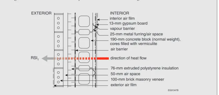
Example 3-11 – Wall: Concrete Masonry Wall (no interior framing)
Figure A shows a concrete masonry wall with no interior framing.
13-mm gypsum board
25-mm metal furring/air space
100-mm brick masonry veneer interior air film
INTERIOR EXTERIOR
exterior air film 50-mm air space air barrier vapour barrier
76-mm extruded polystyrene insulation 190-mm concrete block (normal weight), cores filled with vermiculite
EG01347B
RSIT direction of heat flow
Figure A
Example 3-11 – Wall: Concrete Masonry Wall (no interior framing) (Continued)
Since the wall assembly does not use framing, the Isothermal Planes Method is used to calculate the overall thermal transmittance of the wall. The RSI values of all the assembly’s components can be obtained from Tables 3-4 to 3-8 (see Paragraph 70), taking into account the thickness of the materials and the RSI values of the interior and exterior air films. The overall thermal transmittance, UT,
can be calculated as follows:
Assembly Components RSI, (m2·K)/W)
Exterior air film 0.03
100-mm brick masonry veneer 0.07
50-mm air space(1) 0.18
76-mm extruded polystyrene insulation 2.66
Liquid-applied air barrier 0.00
190-mm concrete block (normal weight), cores filled with vermiculite
0.51
25-mm air space 0.18
Vapour barrier 0.00
13-mm gypsum board 0.08
Interior air film 0.12
RSIT 3.83
UT= 1/RSIT 0.261
(1) The air space in this Example’s masonry cladding system with weep holes at its base is considered, in this illustrative calculation
only, to be an enclosed air space as described in the “ASHRAE Handbook – Fundamentals.” The most appropriate means of determining the overall thermal values, whether by calculation or by laboratory testing per NECB Sentence 3.1.1.5.(5), must be carefully considered for each situation.
Prescriptive Path Method of Compliance (Section 3.2.)
42. The prescriptive path method of compliance establishes the minimum acceptable thermal
performance requirements for the building envelope and includes specific requirements for energy efficiency. It includes general requirements related to the protection of insulation materials, the continuity of insulation and the maximum allowable total vertical fenestration and door area to gross wall area ratio (FDWR). The prescriptive path also includes specific requirements related to the thermal characteristics of above-ground components of the building envelope, building assemblies in contact with the ground and the control of air leakage. With the prescriptive path method, building envelope compliance is achieved when all of the requirements in NECB Section 3.2. are met.
43. The requirements for above-ground components of the building envelope include specific criteria for
vestibules, thermal design criteria for above-ground opaque building assemblies (exterior walls, roofs and exposed floors), and thermal design criteria for fenestration, doors and access hatches. The thermal design criteria are expressed in terms of a maximum overall thermal transmittance value (U-value), based on the HDD for the building location.
44. NECB Sentence 3.2.1.1.(1) requires that the building envelope be designed to limit the key factors
affecting the field performance of thermal insulation. Conditions from both the interior and exterior building envelope environments, including air leakage and convection, wetting and moisture bypassing the plane of thermal resistance, affect the performance of the materials that make up the building envelope. Proper detailing for the management of water, vapour and thermal transfer in building assemblies is necessary for overall performance and durability.
45. Heat, air and moisture transfer through the building envelope are distinct issues but must be dealt
with simultaneously. The various components that make up a building envelope assembly perform different but interrelated functions. Although thermal insulation, for example, is used to control heat transfer, it can also reduce the likelihood of condensation within a wall cavity. The proper control of heat, air and moisture through building envelope assemblies directly impacts the thermal performance of such assemblies.
46. Insulation materials are most effective when installed in accordance with the manufacturer’s
recommendations and in a manner that will achieve the expected thermal resistance of the insulation. For example, compressing insulation reduces its effective thermal resistance and consequently increases the U-value of the building envelope assembly.
Spaces Heated to Different Temperatures (Article 3.2.1.3.)
47. NECB Sentence 3.2.1.3.(1) provides the equation to calculate the maximum allowable U-value
for situations where a building assembly separates interior conditioned spaces that will be
simultaneously heated to temperatures that differ by more than 10°C, for example, walls separating an office space from a refrigerated warehouse as presented in Example 3-12.
48. For heat flow calculations and heating system sizing, the most severe outdoor conditions that are
likely to occur are used. For t0in the equation in NECB Sentence 3.2.1.3.(1), the 2.5% January design
temperature is used as the outdoor design temperature, which represents a design condition that occurs all but 2.5% of the time. For 2.5% of the time, the building envelope will likely be subject to colder temperatures. If heating systems are closely sized to the calculated heat loss results, and actual outdoor temperatures fall below the winter design value, the system will not maintain the required indoor temperatures. In practice this is rather unlikely, since boilers and other heating equipment only come in certain size ranges, and so may be slightly oversized. NECB Table C-1 provides January winter design temperature values for 1% and 2.5%. The 2.5% winter design temperature is normally used. However, if there is a critical need to maintain indoor temperatures, the 1% (or an even more stringent design temperature) could be used.
Example 3-12 – Maximum Overall Thermal Transmittance of Assemblies Separating Spaces Heated to Different Temperatures (Δ > 10°C)
A food distribution company in Winnipeg, Manitoba is building a warehouse with office space. The warehouse will be maintained at 10˚C to prevent food spoilage and the swelling of canned goods; the office space will be maintained at 22˚C. The warehouse and office share a common wall. According to NECB Table C-1, Winnipeg has a 2.5% January design temperature of −33°C and an HDD below 18˚C of 5670, which corresponds to Zone 7A (see Table 3-1 in Paragraph 10). According to NECB Table 3.2.2.2., the maximum overall thermal transmittance (U-value) of above-ground walls in Zone 7A is 0.21 W/(m2∙K).
The maximum U-value of the wall separating the warehouse and office spaces is calculated using the equation in NECB Sentence 3.2.1.3.(1) as follows:
Therefore, the maximum overall thermal transmittance value of the wall separating the warehouse and office spaces is 0.345 W/(m2∙K).
Allowable Fenestration and Door Area (Article 3.2.1.4.)
49. Since fenestration and door components can have a significant impact on the overall thermal
performance of the building envelope, a maximum allowable total vertical fenestration and door area to gross wall area ratio (FDWR) is prescribed in the prescriptive path based on HDD values for the building location. For locations that have between 4000 and 7000 HDD, the FDWR is determined based on a linear equation found in NECB Sentence 3.2.1.4.(1). The maximum allowable FDWR decreases with an increased HDD. The FDWR is a fixed value for locations below 4000 HDD and above 7000 HDD.
50. Figure 3-4 shows a graphical representation of the FDWR equations.
0.45 0.40 0.35 0.30 FD WR 0.25 0.20 0.15 3000 4000 5000 6000
Heating degree-days of building location (HDD) 7000 8000
Maximum allowable vertical fenestration and door area to gross wall area ratio (FDWR)
EG01334B Figure 3-4
Graph showing FDWR equations
Example 3-13 – Calculating Maximum Allowable FDWR
The HDD value for a particular location can be found in NECB Table C-1. The HDD for Flin Flon, Manitoba is 6440. The FDWR can then be calculated using the following equation from NECB Sentence 3.2.1.4.(1):
Example 3-14 – Determining FDWR Compliance with the Prescriptive Requirements
A five-storey condominium building is proposed for Richmond, British Columbia. The building measures 12 m wide × 16 m long × 16 m high. There are four units on each floor. The designer proposes that each unit have two windows on each of its two exterior walls. Each window measures 1.5 m wide × 1.5 m high. On the ground floor, each facade includes two doors, each measuring 2.1 m high × 0.9 m wide. The floor-to-floor height is 3.2 m. Figure A shows a sketch of the building.
1.5 m 12 m 16 m 3.2 m 2.1 m 0.9 m EG01335B 16 m Figure A Sketch of building
According to NECB Table C-1, Richmond has an HDD below 18˚C of 2800. As per the prescriptive requirements in NECB Sentence 3.2.1.4.(1), the maximum allowable FDWR is 0.40.
To determine whether the proposed building satisfies the prescriptive FDWR requirements, the gross wall area of the building is calculated as described in NECB Sentence 3.1.1.6.(3).
The gross wall area is calculated to be 896 m2. The maximum allowable FDWR is 0.40 in the
prescriptive path, which is multiplied by the gross wall area for a maximum allowable fenestration and door area of 358 m2. The gross area of the proposed windows and doors is calculated to
be 195 m2.
The FDWR for this Example is 0.22 (195 m2/896 m2). Since the FDWR is less than the prescriptive
Thermal Characteristics of Fenestration and Doors (Articles 3.2.2.3. and
3.2.2.4.)
51. The energy performance of fenestration and doors has a significant impact on the energy efficiency
of a building. Due to their nature and function, these components of the building envelope are typically less energy-efficient than other above-grade assemblies, and as such, their proper selection is an important opportunity to improve the energy performance of the entire building envelope.
52. The NECB Part 3 requirements for the maximum U-value of fenestration and doors vary based on
the applicable HDD category for the building, as is the case with opaque building assemblies. Fenestration assemblies include windows, skylights, clerestories, translucent wall panels, glass blocks, transoms, sidelights, glass doors (sliding, overhead or swinging), inserts in doors and other assemblies (including their frames) that transfer visible light. Doors include access hatches. There are no thermal requirements for storm doors, automatic sliding doors, glass doors, revolving doors and fire shutters since these types of doors typically cannot achieve the performance levels of other doors due to their function and properties.
53. The numerous design options for fenestration and doors—such as type of framing material,
frame colour, number of glazing layers, glass type, spacer systems, tints, coatings, films, and gas filling—are variables that have an impact on energy performance.
54. Two properties that are used to describe the thermal performance of fenestration and doors are
U-value and Solar Heat Gain Coefficient (SHGC). The U-value is a measure of the overall heat transfer through the entire fenestration or door product, including the frame, the glass edge and the centre of the glass. It represents the overall rate of heat transfer through all of these components and is measured in W/(m2∙K). Although the NECB does not include any specific requirements for SHGC,
selecting fenestration and door products with SHGC values that are appropriate for a particular building has an impact on building heating and cooling loads. The SHGC represents the amount of incident solar radiation transferred through a product, expressed as a decimal fraction between 0.0 and 1.0. The lower the SHGC value, the lower the amount of solar heat gain. Fenestration with a high SHGC value can help reduce heating costs, while products with low SHGC values can help reduce cooling costs. The proper selection of fenestration and door products requires consideration of the entire building design, including location, orientation, exterior shading, thermal properties, and areas of fenestration and doors.
55. The prescriptive requirements for the U-value of fenestration and doors range from 2.1 W/(m2∙K) for
Zone 4 building locations to 1.4 W/(m2∙K) for Zone 8 building locations. The range of fenestration
and door products that meet the NECB prescriptive requirements is broad. A U-value of 2.1 W/(m2∙K) can typically be achieved using, for example, a thermally broken aluminum frame,
double-glazed units with a low-emissivity coating, a non-metallic spacer and argon gas fill. A U-value of 1.4 W/(m2∙K) can typically be achieved using, for example, a thermally broken aluminum
frame, triple-glazed units with a low-emissivity coating, a non-metallic spacer and argon gas fill.
56. The directional orientation of building assemblies can affect their heat transfer characteristics.
For example, the same type of glazing could have a greater heat loss when used in a horizontal or low-sloped application (e.g., skylight) compared to a vertical application, due to increased convection between the panes of glass.
Thermal Requirements for Semi-Heated Buildings (Subsections 3.2.2. and
3.2.3.)
57. A semi-heated building with a set-point temperature of less than 15°C is permitted to meet less
stringent building envelope requirements than those for a standard building, provided its annual energy consumption is less than or equal to the building energy target of the reference building, which uses a set-point temperature of 18°C. Examples of semi-heated buildings include, but are not limited to, warehouses, ice rinks, and self-service storage facilities.
58. When the prescriptive path is used to determine the thermal characteristics of building envelope
assemblies for semi-heated buildings, the design data from NECB Table C-1 for heating degree-days (HDD) below 15°C apply. The lower number of heating degree-days listed for semi-heated buildings compared to standard buildings means that, for many locations in Canada, less stringent overall thermal transmittance values (U-values) can be used.
59. Example 3-15 compares the maximum U-values for a semi-heated building and a standard building
in the same location.
Example 3-15 – Determination of the Overall Thermal Transmittance of Building Envelope Assemblies in a Semi-Heated Building
A semi-heated building is proposed for Nelson, British Columbia. According to NECB Table C-1, Nelson has an HDD below 15°C of 2600 and an HDD below 18°C of 3500, which correspond to Zones 4 and 5, respectively (see Table 3-1 in Paragraph 10). According to NECB Tables 3.2.2.2., 3.2.2.3., 3.2.2.4. and 3.2.3.1., the following overall thermal transmittance values apply to building envelope assemblies in these climate zones:
Heating Degree-Days of Building Location, in Celsius Degree-Days Zone 4: < 3000 (Semi-Heated Building) Zone 5: 3000 to 3999 (Standard Building) Building Envelope
Assemblies/Components
Maximum Overall Thermal Transmittance, in W/(m2·K) Above-ground assemblies walls 0.315 0.278 roofs 0.193 0.156 floors 0.227 0.183 Fenestration 2.1 1.9 Doors 2.1 1.9
Assemblies in contact with the ground
walls 0.568 0.379
roofs 0.568 0.379
floors (for 1.2 m) 0.757 0.757
Therefore, a semi-heated building in Nelson, B.C. is permitted to use the maximum U-values for building envelope assemblies in Zone 4 instead of the more stringent ones for its counterpart in Zone 5 (standard building).
In some locations, the climate zone that applies to standard buildings and semi-heated buildings is the same. For example, in Abbotsford, B.C., the values for HDD below 15°C and below 18°C (2000 and 2860, respectively) both correspond to climate zone 4. Similarly, in Kuujjuaq, Que., the values for HDD below 15°C and below 18°C (7520 and 8550, respectively) both correspond to climate zone 8. In such cases, the maximum overall thermal transmittance values for building envelope assemblies, fenestration and doors are the same for both standard and semi-heated buildings.
In other locations, the climate zone that applies to semi-heated buildings is removed by more than one zone from the climate zone that applies to standard buildings. For example, in Smith River, B.C., the values for HDD below 15°C (5980) and below 18°C (7100) correspond to Zones 7A and 8, respectively, which represents a reduction of two climate zones when determining the maximum overall thermal transmittance values for building envelope assemblies of semi-heated buildings.
Air Leakage (Subsection 3.2.4.)
60. Many functions of the building envelope rely on adequate air leakage control. NECB Sentence
3.2.4.1.(1) requires that the building envelope be designed and constructed with a continuous air barrier system to control air leakage into and out of the conditioned space. The uncontrolled infiltration and exfiltration of air through the building envelope can lead to increased heating and cooling loads. An effective air barrier system is continuous and minimizes air leakage, and can reduce the energy needed for heating and cooling.
61. Air barriers consist of materials that are combined to form assemblies that are ultimately connected
over the entire building envelope to provide an effective barrier to air leakage. As stated in NBC Article 5.4.1.2., air barrier materials must have leakage rates no greater than 0.02 L/(s∙m2) measured
at a pressure differential of 75 Pa in accordance with ASTM E 2178, “Air Permeance of Building Materials,” or CAN/ULC-S741, “Air Barrier Materials – Specification.” As stated in NECB Sentences
3.2.4.2.(2) and (3), air barrier assemblies for opaque elements must have a leakage rate no greater than 0.2 L/(s∙m2) measured at a pressure differential of 75 Pa in accordance with CAN/ULC-S742,
“Air Barrier Assemblies – Specification,” or ASTM E 2357, “Determining Air Leakage of Air Barrier Assemblies.” While the NECB does not require entire buildings to undergo airtightness testing, attention should be paid to the airtightness of joints between assemblies.
62. NECB Articles 3.2.4.3. and 3.2.4.4. specify the maximum allowable air leakage rates for fenestration
products, including metal and glass curtain walls, fixed windows and skylights, and operable windows and skylights, as well as doors, including revolving and automatic commercial sliding doors, overhead doors and main entry exterior doors.
Simple Trade-off Path Method (Subsection 3.3.1.)
63. The simple trade-off path method of compliance offers designers flexibility in satisfying the NECB
requirements for the building envelope. In this method, the reference building is defined as a building whose building envelope complies with the prescriptive requirements of the NECB. However, there are some restrictions on the types of trade-offs permitted.
64. Compliance with the simple trade-off path is determined using the equation in NECB Sentence
3.3.1.2.(2) to demonstrate that the sum of the areas of all above-ground assemblies of the building envelope multiplied by their respective U-values for the proposed building is not more than that for the reference building (based on the prescriptive limits).
65. The simple trade-off path method only addresses deviations from the maximum overall thermal
transmittance of above-ground assemblies and the allowable fenestration and door areas (per the FDWR). The sum of the assembly UAs (U-values multiplied by assembly areas) of the proposed building is consistent with the prescriptive limits. The two input parameters are the U-values of the assemblies and the areas, and either or both of these can vary within the simple trade-off rules. The simple trade-off path can be used in several ways. For example, a building may be allowed to have an FDWR that exceeds the maximum allowable value, provided that above-ground assemblies have more stringent U-values. Alternatively, a building with an FDWR that is lower than the maximum allowable value may be allowed to use assemblies with U-values that exceed the maximum allowable values. The U-values of above-ground assemblies can also be traded-off against each other. For example, an above-ground exterior wall assembly that has a U-value that exceeds the maximum allowable value may be permitted if a fenestration system with a lower U-value (i.e., more stringent) is used.
66. This method of compliance includes restrictions regarding the type of trade-offs that are
permitted: vertical above-ground building assemblies can only be traded-off against other vertical above-ground assemblies; horizontal above-ground assemblies can only be traded-off against other horizontal above-ground portions; and trade-offs with assemblies in contact with the ground are not permitted. For example, an above-ground exposed floor assembly can be permitted to have an overall thermal transmittance that is higher than what the prescriptive path allows, if it can be shown, through the trade-off calculation, that this deviation can be compensated by selecting a roof assembly that has a lower overall thermal transmittance than what the prescriptive path allows. Trade-offs between FDWR and U-values can only be done on vertical elements (i.e., FDWR vs. U-value of walls, windows or doors). Additions and semi-heated buildings are not permitted to use the simple trade-off path.
67. Within the limitations prescribed in the NECB, the simple trade-off path equation requires that the
sum of the product of the overall thermal transmittances of all of the building envelope assemblies multiplied by their respective areas for the proposed building be equal to or less than that same sum calculated using the prescriptive path values for the reference building. Examples of simple trade-off path calculations are presented in Examples 3-16 and 3-17.
Example 3-16 – Simple Trade-off Path Calculation for Commercial Building
A one-storey community centre is proposed for Winnipeg, Manitoba. The building has a gross wall area of 560 m2. According to NECB Table C-1, Winnipeg has an HDD below 18°C of 5670, which
corresponds to Zone 7A (see Table 3-1 in Paragraph 10). Using the prescriptive path, the maximum allowable FDWR for a building located in Winnipeg is 0.289 (FDWR = 2000 – 0.2 × HDD ÷ 3000); however, based on the owner’s requirements, the proposed design has an FDWR of 0.32.
According to the prescriptive requirements for Zone 7A, above-ground walls are required to have an overall thermal transmittance (U-value) of not more than 0.21 W/(m2∙K) and both fenestration and
doors are required to have a U-value of not more than 1.90 W/(m2∙K). Using the maximum allowable
FDWR of 0.289, the UA of the prescriptive building is calculated as follows: Prescriptive Path (Reference Building)
Building Envelope Assembly
Prescriptive Path
U-Value (Uir), W/(m2·K) Area (Air), m2
Area Ratio due to
Maximum FDWR UA (Uirx Air), W/K
Walls 0.21 398.16 0.711 83.61
Fenestration and doors 1.90 161.84 0.289 307.50
Totals: 560 1 391.11 (391)
Following the method of the simple trade-off path, the owner’s requirement for a higher FDWR can be traded-off against the U-values for the fenestration and doors and/or walls, since these assemblies are vertical above-ground portions of the building envelope, provided that the sum of the UAs (ΣUA) of the proposed building does not exceed the ΣUA of the reference building (391 W/K in this Example).
In order to show compliance using the proposed FDWR of 0.32, the designer applies the simple trade-off calculations using fenestration and doors with lower U-values (i.e., better performing than prescriptive). As shown in Option 1, by using fenestration and doors with U-values of 1.70 W/(m2∙K),
the ΣUA of the proposed building (385 W/K) remains below that of the reference building (391 W/K) and the design is compliant with the trade-off path.
Option 1 – Simple Trade-off Path (Proposed Building) Building Envelope
Assembly
Required U-Value (Uip),
W/(m2·K) Area (Aip), m2
Area Ratio due to Design
Requirements UA (Uirx Air), W/K
Walls 0.21 380.80 0.68 79.97
Fenestration and doors 1.70 179.20 0.32 304.64
Totals: 560 1 384.61 (385)
The designer could also use a combination of measures to lower the U-value of the proposed building, for example, by modifying the U-values of both the walls and the fenestration and doors. In the calculation in Option 2, the U-value of the fenestration and doors is again decreased, but this permits an increased wall U-value.
Option 2 – Simple Trade-off Path (Proposed Building) Building Envelope
Assembly
Required U-Value (Uip),
W/(m2·K) Area (Aip), m2
Area Ratio due to Design
Requirements UA (Uirx Air), W/K
Walls 0.27 380.80 0.68 102.82
Fenestration and doors 1.60 179.20 0.32 286.72