Publisher’s version / Version de l'éditeur:
Thermal spray connects : explore its surface potential!, ITSC 2005, International
Thermal Spray Conference & Exposition, conference abstracts, pp. 1133-1138,
2005
READ THESE TERMS AND CONDITIONS CAREFULLY BEFORE USING THIS WEBSITE. https://nrc-publications.canada.ca/eng/copyright
Vous avez des questions? Nous pouvons vous aider. Pour communiquer directement avec un auteur, consultez la
première page de la revue dans laquelle son article a été publié afin de trouver ses coordonnées. Si vous n’arrivez pas à les repérer, communiquez avec nous à [email protected].
Questions? Contact the NRC Publications Archive team at
[email protected]. If you wish to email the authors directly, please see the first page of the publication for their contact information.
NRC Publications Archive
Archives des publications du CNRC
This publication could be one of several versions: author’s original, accepted manuscript or the publisher’s version. / La version de cette publication peut être l’une des suivantes : la version prépublication de l’auteur, la version acceptée du manuscrit ou la version de l’éditeur.
Access and use of this website and the material on it are subject to the Terms and Conditions set forth at
Alumina-Titania Coatings Deposited by Laser-Assisted Air Plasma
Spraying: Microstructure and Mechanical Characterization
Dubourg, L.; Lima, R. S.; Moreau, C.
https://publications-cnrc.canada.ca/fra/droits
L’accès à ce site Web et l’utilisation de son contenu sont assujettis aux conditions présentées dans le site LISEZ CES CONDITIONS ATTENTIVEMENT AVANT D’UTILISER CE SITE WEB.
NRC Publications Record / Notice d'Archives des publications de CNRC:
https://nrc-publications.canada.ca/eng/view/object/?id=8ddf178a-9113-40d2-9960-d9329b57c31f
https://publications-cnrc.canada.ca/fra/voir/objet/?id=8ddf178a-9113-40d2-9960-d9329b57c31f
IMI2004-105575-G
CNRC
46955
Alumina-titania coatings deposited by laser-assisted
air plasma spraying: microstructure
and mechanical characterization
L. Dubourg, ATC - NRC, R. S. Lima, IMI- NRC, C. Moreau, IMI- NRC
Alumina-titania coatings deposited by air plasma spraying (APS) are widely used to protect components against wear at low temperatures. It is known that microstructures formed by the post-laser remelting of as-sprayed coatings exhibit a densification but also numerous macrocracks due to the rapid cooling and thermal stresses. By using the laser-assisted air plasma spraying (LAAPS), the laser beam interacts simultaneously with the plasma torch in order to increase coating surface temperature and possibly superficially remelt the coating. As a result, the microstructure is partially densified and macrocracks, which are generally produced in the post-laser irradiation treatment, can be inhibited. In addition, this hybrid spraying can be done without the post-treatment of coating. In this paper, LAAPS was performed to improve the mechanical properties of Alz03-13%TiOz coatings. The coating microstructure was characterized by SEM and X-ray diffraction. The mechanical characterization was done by hardness measurements, erosive wear tests and abrasion wear tests. Results showed that laser assistance may induce: (1) the disappearance of vertical and horizontal macrocracks due the laser irradiation in the coatings for a laser irradiation density lower than 34 W.mm-z, (2) an important decrease of the amount of microcracks in the deposited splats, (3) the partial transformation of the metastable y-Alz03 phase in the equilibrium a-Alz03 phase, (4) a hardness increase of 11%, (5) an improvement of the erosive wear resistance by 12% and (6) an improvement of the abrasive wear resistance by 38%.
1
Introduction
Alumina-titania coatings produced by air plasma spraying (APS) have been widely used to protect components against wear at low temperatures (1-3). However, APS ceramic coatings contain connected porosity and their properties such as high temperature corrosion resistance, mechanical strength, and erosion resistance can be, thereby, greatly reduced. To improve these properties, various methods have been proposed such as post-laser irradiation and seal sintering with liquid alloys (4-12). Laser irradiation is an efficient method for densifying the microstructure of the ceramic coatings. However, in post-laser irradiation treatment, it is difficult to suppress the formation of macrocracks during the process of rapid cooling due to the excessive thermal contraction of the densified microstructure (4, 6-8, 10, 13, 14). Laser-assisted air plasma spraying (LAAPS) consists of APS with the simultaneous laser beam irradiation. This method has been studied to deposit ZrOz ceramic with Ni-based bond coat
(4-7,
13, 14), Cr3CZ cermet (15), Alz03 based ceramic (1, 12, 16) and TiNi metallic alloy (17). This process enables control of the coating microstructure in a single process: melted powders are sprayed from a plasma gun, and heat control of the powders impinging on the substrate is performed by laser irradiation. According to recent studies, LAAPS seems to be effective in preventing the formation of cracks and in maintaining an appropriately densified microstructure(4-7,
13,14). In this study, alumina-titania coatings were prepared by yttrium-aluminum-garnet (YAG) laser-assisted plasma hybrid spraying. Wear resistance properties were evaluated in relation to changes in the coating microstructure. The properties of such coatings were compared with those of plasma as-sprayed coatings.
2
Experimental set-up
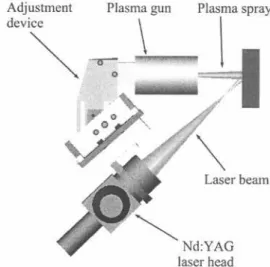
Fig. 1 shows the experimental set-up of LAAPS. The laser beam was aimed at the spraying point, which overlapped the particle footprint on the substrate surface. The laser head was attached to the plasma torch and was scan with it at a transverse speed of 6
m/s by a 6-axis robot. The particle stream was almost
normal to the surface sample, while the angle between the laser beam and the plasma spray was set at 45°.
Laser beam
~
Nd:YAG laser headFig. 1. Experimental set-up for laser-assisted air plasma spaying.
The samples consisted of 500-llm-thick APS-sprayed Alz03 - 13%TiOz coatings (Metco 130 powder) and 150 11m-thick APS-sprayed Ni-Cr-AI-Y bond coat (Praxair Ni-164-2 powder) on low carbon steel substrates (length: 76,2 mm, width: 25,4 mm, thickness: 12,7 mm). Substrates were grit-blasted before spraying. The spray parameters employed in this work are listed in Table 1. During the APS process a cooling system (air jets) was
applied to
reduce coating temperature, which was monitored by using an optical pyrometer. The maximum coating temperature while depositing coatings to a thickness of approximately 500 J.lm did not exceed 170°C. LAAPS was not used during the bond coat deposition.
Table 1. Spray parameters used for the APS torch
Primary gas (Ar) flow (I.min-') Secondary gas (H2) (I.min-1) Current (A)
Voltage (V) Power (kW)
Carrier gas (Ar) flow (I.min-1) Powder feed rate (g.min-1) Spray distance (mm) AI203
-
13%Ti02 50 1.6 800 38.8 31 7 20 63 Ni-Cr-AI-Y 50 23.6 700 35.8 25 6.5 30 63LAAPS was carried out using a 2000 W continuous wave Nd:YAG laser of 1.064-J.1m
wavelengthand a
1-mm diameter optical fiber. A lens with a 200 1-mm focal length was used to focus the laser beam. The laser power was adjusted to 1650 W on the workpiece surface. The changes of laser irradiation density offered during hybrid spraying were controlled by adjusting the defocus distance of the laser beam irradiating the specimen surface, whereas the power of plasma spraying was maintained at a constant value. The relationship between defocus distance, spot diameter of the laser beam and laser irradiation density is shown in Table 2. Distribution of the laser beam evolved from a top hat profile at the focus point to a gaussian profile at a defocused position
(4).
Table 2. Relationship between defocus distance, spot diameter of the laser beam and laser irradiation density Defocusdistance (mm) 30 40 50 60 70 Spot diameter (mm) 6 8 10 12 14 Power density (W.mm-2) 60 34 22 15 11
The cross-section of the coatings was vacuum impregnated with a low viscosity epoxy and then polished to a mirror finish (diamond with grain size of
1
J.1m).The cross-section microstructures were
evaluated via scanning electron microscopy (SEM). Phases were identified by X-ray diffraction using a Bruker AXS D8-Discover diffractometer (CuKa radiation). Vickers micro-hardness measurements were performed in the cross section with a load of 3 N.
The slurry-erosion test was carried out in equipment built in-house. Alumina #100 (150 J.lm)was employed as erodent. The liquid part of the slurry was made with neutral pH deionised water and the erodent concentration was 0.66% by weight. The slurry jet
had a constant flow rate of 1 I/min (6.6 g/min of alumina particles) and a constant velocity of 20 m/s. The slurry-erosion resistance was evaluated at the impinging angle of 90° during five minutes for each sample. Three samples were tested for each of the different coating types produced in the study. The volume of the material abraded away during the slurry-erosion test was measured via optical profilometry.
The abrasion resistance of the coatings was tested based on the ASTM standard G6500 (procedure D -modified) (18) also known as the dry sand/rubber wheel test. In this test, a stationary, coated sample was pressed against a rotating rubber-coated wheel (11.43 em radius - 200 rpm) with a force of 45 N. Silica sand (212-300 J.1m)was fed (300-400 g/min) between the coating and rubber wheel until the wheel travelled over the equivalent linear distance of 1436 m. Prior to being submitted to this test, the surfaces of the coatings were prepared by grinding with diamond wheels to produce a flat surface. Two samples were tested for each types produced in the study. The volume of the material abraded away during the abrasion test was measured via optical profilometry.
3 Results and discussion 3.1 Microstructure characterization
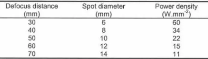
Fig. 2.a shows a typical cross section of an APS alumina-titania coating. The microstructure shows lamellar splat morphology with interlamellar pores, typical of plasma sprayed coating. The other pictures of Fig. 2 show the changes of the microstructure obtained by LAAPS at laser input powers of 60, 34 and 22 W.mm-2. The porosities in the coatings decreased as compared with the APS coating and a good interface between the coating and the bond
coat
was obtained. The density degree of the microstructure of LAAPS layer in the coating increased with a decrease in the defocus distance of the laser beam from 70 mm to 30 mm, corresponding to a laser irradiation density increasing from 11 to 60 W.mm-2. In the case of defocus distance equal or lower than 30 mm, the laser irradiation density was too high, equal or superior to 60 W.mm-2, leading to an excessive melting of the coating and the debonding of the alumina-titania coatings (Fig. 2.b). This phenomenon gets close to the laser remelting of APS coatings studied by many authors in the case of ceramics spraying (4, 6, 7). The excessive coating melting occurred at the area of laser irradiation. A large contraction of the melted part in an extremely short time occurred in the process of rapid cooling after the laser beam irradiation. This causes the appearance of large cracks parallel and normal to the sample surface and, in the extreme cases, the debonding of the coating (Fig. 2.b).
---APS (no laser)
LAAPS (34 W.mm-2)
- LAAPS (60 W.mm-2)
-~
-
~-?'-'-LAAPS (22 W.mm-2)
Fig. 2. Cross-sectional SEM micrographs of: a) an APS coating and b), c), d) LAAPScoatings.
On the other hand, when the laser irradiation density
decreases from 34 to 11 W.mm-z, the coating melting
is not reached and the coating density is high. At 34
W.mm-z, some cracks were still observed as shown
in the Fig. 2.c, nevertheless their number and size
were low. For a laser irradiation density lower than 34
W.mm-z, these cracks were not observed (Fig. 2.d).
The strain of the coating during the solidification was
small as the regions of contraction were limited to the
upper layers of the coating.
At high magnification (Fig. 3.a), the SEM observation
of an APS coating revealed vertical microcracks in
APS (no laser)
the splats of the coating. With the LAAPS use, the
vertical microcracks in the splats were inhibited or
strongly reduced (Fig. 3.b). These microcracks were
inhibited by the heating effect of laser irradiation and
thermal barrier effect of upper layers. This makes the
particles to cool at a slower speed,
limiting the
thermal stress. Moreover, the laser irradiation can
partially remelt the upper layers of the alumina-titania
coatings during the process. This can cause the
elimination of microcracks.
LAAPS (34 W.mm-2)
As shown in the Fig. 4.b, XRD phase analysis revealed that the as-sprayed coating predominantly consists of the metastable y-A1203 phase. The thermodynamically stable a-A1203phase is present in a small quantity. Early experiments with thermally spray alumina deposits showed that the metastable y-AI203 structure was produced rather than a-A1203 (19). This can be explained based on nucleation kinetics; y-A1203 is more easily nucleated from the melt than a-A1203 because of a lower interfacial energy between crystal and liquid and, at sufficiently rapid cooling rates, the metastable form is retained at room temperature (19).
The same observationcan be
done on the coatings obtained by LAAPS as shown in the XRD pattern of Fig. 4.a carried out with a laser irradiation density of 22 W.mm-2. At this laser irradiation density, macrocracks were not observed (see Fig. 2.d). The LAAPS coatings mainly consist of the metastable y-A1203 phase. However, regarding the relative height and number of diffraction picks, a higher quantity of the stable a-A1203 is formed. This characteristic may be related to a partial remelting of the coating during the process or to a slowly solidification rate of the molten phase during spraying. Indeed, the laser remelting leads to a lower solidification rate than the APS one as reported by Krishnan et al. (11). Furthermore, the solidification rate is also reduced by the heating effect of laser irradiation on the sample surface and thermal barrier effect of upper layers. This lower solidification rate can cause the partial equilibrium solidification and the precipitation from the metastable y-Al203 to the stable a-AI203. The formation of a-A1203 during LAAPS is highly desirable because this phase exhibits improved mechanical properties when compared to y-AI203 (20). This should help to enhance the mechanical performance of the coatings, as shown in Section 3.2.
a) APS assisted by laser I y
(22 W.mm2) y
20 30 40 50 60 70
b) APSwithout laser y
y
20 30 40 50
26
Fig. 4. XRD patterns of alumina-titania coatings
obtained by a) LAAPSwith a laser irradiationdensity
of 22 W.mm-2,b) APS withoutlaser.
60 70
3.2 Mechanical characterization
Fig. 5 shows the hardness in the cross section of APS alumina-titania coating (dark line) and coatings obtained by LAAPS, laser irradiation density evolving from 11 to 34 W.mm-2. Hardness values of LAAPS coatings obtained with a laser irradiation higher than 13 W.mm-2 were higher than that of the APS coating (1093 HVo.3). The maximum value was 1210 HVo.3, corresponding to a hardness increase of 11% compared with the APS coating. As shown in the Fig. 5, the hardness increases with the increase of the laser irradiation density and the decrease of the defocus distance. Similar observations were reported by several authors (4, 6). Fig. 5 indicates a linear correlation between hardness and laser irradiation density. The hardness increase can be explained by the following points. (i) The surface temperature of the sprayed particles was raised when they entered into the area of laser irradiation. Moreover, the sample surface temperature was also increased by the laser beam. This resulted in an increase of the wettability of the sprayed particles, the bonding areas among the particles and the strengthening of the bonding force among the particles. (ii) The
a-A1203
phase is partially precipitated instead of y-A1203one.
1400 1200 .. >d ~ ::: 1000 CD C 'tI... cu :I:
APS without las8 -~ ~---800 600 10 80 15 20 25 30
Laserirradiationdensity(W.mm-2) Fig. 5. Hardness evolution of APS and LAAPS coatings as function of the laser irradiation density. The hardness of APS coatings and its standard deviation are shown respectively by the dark and the dash lines.
35
80
LAAPS improved the erosive wear resistance in the laser irradiation density range of 15-22 W.mm-2, as reported in the Fig. 6. Outside this range, the wear rate is higher than 12.2 mm3.kg-1, the value measured on the APS coatings. The best result is achieved for a laser irradiation density of 18 W.mm-2, leading to a wear rate of 10.8 mm3.kg-1and erosion resistance improvement of 12%. The benefits of LAAPS can result from the following points. (i) The vertical microcracks in the splats were inhibited by the laser irradiation. This phenomenon decreases the fracture and the removal of the coating splats during the impacts of erosive particles.
(ii) As for the
hardness improvement, LAAPS resulted in an increase of the wettability of the sprayed particles, the bonding areas among the particles and the strengthening of the bonding force among the particles. (iii) The a-A1203 phase with enhanced
mechanical properties is partially precipitated instead of y-Al203 one. When the laser irradiation density is higher than 22 W.mm-2, the erosive wear rate is higher than the one measured on the APS coatings. The previous benefits are then balanced by the appearance of cracks parallel to the sample surface (see Fig. 2), with the subsequent decrease of the strengthening of the coatings. On the other hand, when the laser irradiation density is lower than
15
W.mm-2,
the wear resistance is also lower than the one measured on the APS coatings. In this case, the laser irradiation density can be not enough to induce the previous benefits but there is probably a significant increase in the temperature of the coating under the laser spot. It has been demonstrated that thermal spray ceramic coatings deposited on hot coating/substrates tend to exhibit significant more cracking during mechanical solicitation when compared to the same coating deposited on cooler conditions(21).
Therefore, the low performance of the coatings produced at low laser irradation density is probably explained by their tendency of severe cracking under mechanical efforts.16
+
... /// '01 ~ 15 ~Eg
14*
'- ~ t,I"
ro 13 uuu~
---.~ 12 \.uuu . ..+' (/)J
\,-.J]
11--./
,
T/
/\ / APS without laser
~
J_---10
15 20 25 30 35
Laser Irradiation density (W.mm-2) Fig. 6. Relationship between laser irradiation density and erosive wear rate for LAAPS coatings. The erosive wear rate of APS coatings and its standard deviation are shown respectively by the dark and the dash lines.
10
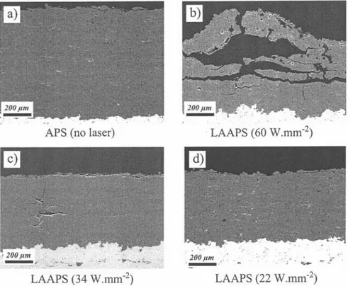
Fig. 7 shows the abrasive wear resistance evaluated on the coating surface obtained by APS and LAAPS. The volume loss of the APS coatings was about 17.6 mm3. This value is reduced b~ the LAAPS use, up to a minimum value of 11.0 mm with a laser irradiation density of 22 W.mm-2, The volume loss during abrasive wear is then reduced by 38%. As shown in the Fig. 7, the volume loss decreased considerably with an increase of the laser irradiation density from 11 to 22 W.mm-2. As for the erosive resistance, this improvement of the abrasion property can result from the increase of bonding areas and strengthening of the bonding force among the particles, the inhibition
of the vertical microcracks in the splats and the partial precipitation of a-A1203 phase. Moreover, LAAPS coatings showed a higher hardness than the APS coatings. This higher hardness reduces the scratch effect of the abrasive particles and, in consequence, the volume loss. On the other hand, the volume loss increased between 22 to 34 W.mm-2, although it was lower than one of APS coatings. This decrease of abrasive wear resistance can be also explained by the appearance of cracks parallel to the sample surface in LAAPS coatings obtained with the highest laser irradiation densities. During the wear, these cracks can cause the delamination of large debris. Contrary to the erosive wear test, this phenomenon does not balance the benefits of LAAPS.
25
~
~E .§.
201 -- - -- ~'- U U - -- -- no U - no - U u~~ ~~~~t ~~s~! 2 e! '-ro Q) ~ 15~
'Uj e! .a«
~---,
\.\
+
.*/. "~ ",/ ~-10 15 20 25 30Laser irradiation density (W.mm'2)
Fig. 7. Relationship between laser irradiation density and abrasive wear rate for LAAPS coatings. The abrasive wear rate of APS coatings and its standard deviation are shown respectively by the dark and the dash lines.
10 35
4
Conclusions
This study concern the deposition of alumina-titania coatings by laser-assisted air plasma spraying using a 2 kW Nd:YAG laser. The possibilities of this hybrid process were investigated, especially the laser irradiation density effects on the microstructure and the mechanical properties of alumina-titania coatings. The results are summarized as follows. (1) Vertical and horizontal macrocracks due the laser irradiation were not observed in the alumina-titania coatings for a laser irradiation density lower than
34
W.mm-2. (2) Microcracks in the deposited splats were inhibited or strongly reduced. (3) The metastable y-A1203phase was partially transformed in the equilibrium a-A1203 phase. (4) The coating hardness is increased by a ratio of 11%. (5) The erosive wear resistance is improved by a ratio 12%. (6) The abrasive wear resistance is enhanced by a ratio of 38%.5 Acknowledgements
The authors thank S. Belanger for APS spraying, B. Harvey and M, Larouche for LAAPS spraying and erosive tests, J. F. Alarie for abrasive tests, M. Lamontagne for optical profilometry measurements,