HAL Id: hal-02526877
https://hal.archives-ouvertes.fr/hal-02526877
Submitted on 10 Apr 2020HAL is a multi-disciplinary open access archive for the deposit and dissemination of sci-entific research documents, whether they are pub-lished or not. The documents may come from teaching and research institutions in France or abroad, or from public or private research centers.
L’archive ouverte pluridisciplinaire HAL, est destinée au dépôt et à la diffusion de documents scientifiques de niveau recherche, publiés ou non, émanant des établissements d’enseignement et de recherche français ou étrangers, des laboratoires publics ou privés.
HIGH POWER TRANSMISSION USING
CONTACTLESS MICROWAVE TRANSITION ON AN
EMDRIVE SETUP
Hugo Peyre, Olivier Pascal, Jérôme Sokoloff, Kevin Elis, Olivier Pigaglio,
Nathalie Raveu
To cite this version:
Hugo Peyre, Olivier Pascal, Jérôme Sokoloff, Kevin Elis, Olivier Pigaglio, et al.. HIGH POWER TRANSMISSION USING CONTACTLESS MICROWAVE TRANSITION ON AN EMDRIVE SETUP. Progress In Electromagnetics Research Letters, EMW Publishing, 2020, 90, pp.15 - 20. �hal-02526877�
High Power Transmission Using Contactless Microwave Transition
on an EMDrive Setup
Hugo Peyre1, *, Olivier Pascal1, J´erˆome Sokoloff1, Kevin Elis2, Olivier Pigaglio1, and Nathalie Raveu1
Abstract—In this paper, a contactless microwave transition is described and characterized. In our “ElectroMagnetic Drive” (EMDrive) measuring setup, it will be dedicated to transmit high Radio Frequency (RF) powers without any mechanical effort. It exhibits very good matching and transmission performances. It is found to transmit 100 W microwave power range at 2.45 GHz without any visible mechanical effect on a 10 mg precision balance, contrary to a previous coaxial cable. This device appears useful to every EMDrive setup and can be easily implemented.
1. INTRODUCTION
The concept of EMDrive electromagnetic thruster is one of the most controversial scientific topics in the past few years. Indeed, recent articles [1–5] attempt to demonstrate or refute the presence of a tiny force produced by asymmetrical resonant microwave cavities. The proof of such a force can only be experimental since it violates the action-reaction law, and until now, no theoretical model can explain this phenomenon.
The greatest challenge of these experimental investigations is to transmit microwave power to feed resonant cavities without affecting the measurement of the potential EMDrive force. Indeed, in order to measure tiny forces hypothetically produced, the most important thing is to mechanically split the system from its power supply unit, part of the external environment. Among the latest EMDrive experimental configurations that can be found in the literature [1–3], some solutions have been implemented, making it possible to reduce or even to almost eliminate the parasitic effects caused by the feeding of the cavity.
In 2016, White et al. [1], from Eagleworks Laboratories, published the first peer-reviewed paper in which they report using liquid metal contacts to transmit Direct Current (DC) power (and control signals) to supply (and drive) the power unit feeding the cavity. In this way, they considerably reduce interface wire forces. K¨oßling et al. [2], from TU Dresden, also implemented, in 2018, a liquid metal contact for an RF feedthrough, in order to avoid parasitic effects due to the thermal effects of the coaxial cable. In both cases, the liquid contact is performed thanks to containers filled with Galinstan, a metal in liquid phase under usual conditions.
In addition to these works,McDonald et al. [3], from Naval Research Laboratory, presented, in 2017, their noncontact RF power transmission, called “finger joint”, but did not report any thrust measurements with this item.
In our previous work [6], we developed an original test facility to measure an EMdrive like force. The chosen configuration, called shaker because of its shape, allowed to alternatively feed two cavities
Received 5 November 2019, Accepted 22 January 2020, Scheduled 4 February 2020
* Corresponding author: Hugo Peyre ([email protected]).
1 LAPLACE, CNRS, Universit´e de Toulouse, Toulouse, France.2Antennas Department, Centre National d’Etudes Spatiales (CNES),
16 Peyre et al.
oriented in opposite directions without the intervention of an operator. The main parasitic effect was related to the unique RF cable that fed the cavities.
Taking advantage of the radiation properties of microwaves to look for genuine contactless power transmission, we present, in this paper, a dedicated transition. To eliminate cable mechanical effects due to thermal effects with typical 100 W power transmission, the requirements for the contactless device are: good matching (reflection< −10 dB), very low losses (conduction or radiation), high level of transmission (transmission> −1 dB), high power handling (max 200 W), two independent transmission channels (shaker capability), 40 MHz bandwidth around 2.45 GHz (cavity tuning), and the lightest possible.
In the following sections, we will first describe the contactless RF transition that we have designed and manufactured (Sec. 2), before characterizing its electromagnetic properties and mechanical behaviour when confronting high RF power (Sec. 3).
2. DESCRIPTION
The designed transition must ensure a total mechanical isolation between the generator and the two cavities, while minimizing leakage to protect involved people from the 100 W range microwave power. We have therefore chosen to use a “groove gap” structure [7, 8] to create a bandstop filter between the inside cylindrical volume and the outside of the transition, without any physical contact between the two parts of the device.
The device has to deal with two distinct RF channels in order to feed one or the other cavity. We then decide to use two head-to-tail septum polarizers [9]. They allow to transmit two RF channels through a single propagation duct (circular waveguide); one channel being in left circular polarization and the other in right circular polarization.
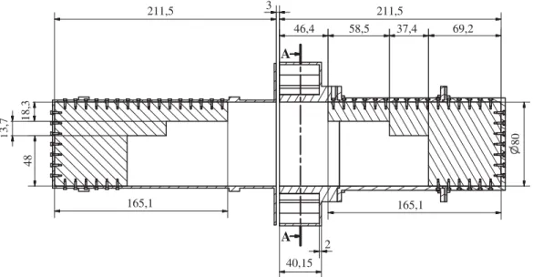
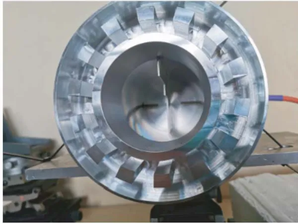
To reduce the total mass of the transition, several design efforts have been made. We work as close as possible to the cut-off frequency of the first propagative mode of the circular waveguide in order to have the smallest diameter possible. We use a septum polarizer with the fewest steps required. We have limited the number of Electromagnetic Band-Gap (EBG) cells. All the dimensions of the contactless transition are specified in the following diagrams (Figures 1 and 2), and pictures of the transition and the EBG structure are displayed in Figures 3 and 4.
A A 211,5 3 46,4 58,5 37,4 69,2 165,1 80 18,3 1 3,7 48 2 40,15 165,1 211,5
Figure 1. Dimensional diagram in the septum plane (values in mm).
The part of the transition positioned on the balance (left part in Figures 1 and 3) has been manufactured with a mass reduction effort, which leads to a 670.9 g mass. Moreover, this part of the transition supports almost no mass of the EBG structure.
132,78 11,83 94 156 13.89 112,56 151,36 o o A-A
Figure 2. Dimensional diagram of the EBG structure (values in mm).
Figure 3. Picture of the contactless RF transition with blue dielectric support (for preliminary tests). 1, 2, 3 and 4 are the port numbers.
Figure 4. Picture of the EBG structure.
The 2-steps septum polarizers are made apart from circular waveguides and mounted together with about 60 screws ensuring proper holding and electrical contact. Actually, these screws, visible in Figure 1, do not pierce the septum but only exert pressure on the edge of it.
3. CHARACTERIZATION
The generator-side transition part is fixed, keeping it leveled while allowing it to be slightly moved. The other part is supported by a shaped polystyrene block positioned on the balance with a 5 mm air gap. All the characterizations presented in this section are performed under this configuration.
3.1. Low Power
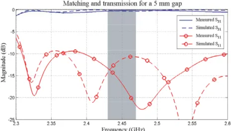
We start by analyzing the electromagnetic behavior of the transition by connecting a 4-port VNA (Vector Network Analyzer). We are then able to compare the measurement of the S-parameters with the simulations previously performed with ANSYS Electronics Desktop (Figure 5).
18 Peyre et al.
Figure 5. Comparison of simulated ant measured S-parameters of the RF contactless transition. S11:
reflection. S31: transmission.
In Figure 5, it can be seen that the measured transmission and matching levels are well suited to the simulation. Port 1 matching exhibits a frequency shift that finally appears advantageous in the targeted bandwidth (shaded area). In this frequency band (2.43–2.47 GHz), the measured matching (solid line with circles) is less than−13 dB, and the transmission (solid line) is greater than −0.4 dB.
Moreover, the measurements of the matching levels of the other ports lead to very similar results. The curves of the two transmission channels merge almost perfectly with levels above −0.4 dB in the relevant bandwidth, while the level of cross-talk is below−40 dB.
One can also note that even better performances can be achieved from such a contactless transition. With this one, the best results are obtained for 3 mm distance and perfect alignment. However, the good characteristics reported here are considered for 5 mm distance and approximate alignment that are representative for simple experimental mounting.
3.2. High Power
In our previous measuring setup [6], the switch used to feed one or the other cavity is directly connected at their inputs. It is part of the Device Under Test (DUT) positioned on the balance and is connected by a single coaxial cable to the power feeder.
In order to characterize the influence on the thrust measurement of the high power transmission in this configuration, the DUT is replaced by a 500 W matched load (Figure 6).
In the next experimental setup, the RF cable will be substituted by the contactless transition to eliminate its parasitic thermal effects. In that case, the switch will be set at the output of the feeder, and its two outputs will be connected to the transition inputs. The cavities, in shaker configuration, can then be directly connected to the two transition outputs, ensuring a total mechanical decoupling from the power supply.
In the same way, by replacing the cavities with matched loads in this setup (Figure 7), we will be able to characterize and compare the influence of power transmission on the thrust measurement (Figure 8).
Figure 8 exhibits the parasitic force (solid line) produced by thermal distortions of the coaxial cable structure as the generator provides 200 W RF power. Actually, considering the attenuations of each component of the feeding circuit, the RF power that passes through the coaxial cable can be estimated around 140 W. The cable therefore exerts an increasing tensile force on the system which causes the constant decrease of the overall weight as long as the microwave power passes through it (similar response to that of the previous paper [6]). Moreover, the curve steps are a good way to check the resolution of the balance, which is 10 mg (i.e., 0.1 mN).
Figure 6. Configuration of the former setup with a RF cable connected to the matched load.
Figure 7. Setup with the contactless transition connected to two matched loads, with a 5 mm gap.
-1 0 1 2 3 4 5 -450 -400 -350 -300 -250 -200 -150 -100 -50 0 50 Acquisition time (s) Weighing (mg) Balance response Coaxial cable
Contactless transition (5 mm gap) Adding of 30 mg -4.5 -4 -3.5 -3 -2.5 -2 -1.5 -1 -0.5 0 0.5 Weighing (mN)
Figure 8. Comparison of effects of the RF cable and the transition on the balance. The responses have been synchronized att = 0 s.
The dashed curve shows that the balance does not measure any force when the contactless transition is connected to the matched loads. In this configuration, the sensitivity of the balance is 30 mg (the black curve with circles is the measurement of a drop of a 30 mg standard weight on the transition). It can therefore be concluded that the contactless transition does not produce any force greater than 0.3 mN. It thus ensures the same function as the cable while totally eliminating its parasitic effects.
Radiation losses are almost nonexistent for a gap of a few millimeters (typically, 5 mm) and remain harmless to the operator, in the immediate vicinity of the transition, up to a gap about 1 cm. Moreover, after a study performed with a thermal camera, it can be stated that the contactless transition practically does not heat up, especially in comparison with the heating of the other elements around it (cables, matched loads).
20 Peyre et al.
4. CONCLUSION
The contactless RF transition we have designed and manufactured successfully meets the desired requirements.
In the operating frequency bandwidth (2.43–2.47 GHz), all accesses are well matched (less than
−13 dB reflection), despite a frequency shift between simulations and measurements. Both transmission
channels are very efficient (more than −0.4 dB transmission), and cross-talk levels are very low (below
−40 dB), allowing us to easily implement the device in our shaker configuration [6].
This transition entirely handles high RF power and can fully ensure the function of our former cable while eliminating any mechanical parasitic effects. Indeed, as expected, our precision balance did not measure any parasitic forces during power-up.
As a conclusion, this contactless transition clearly marks a major improvement in our measuring setup and constitutes a master piece that could be implemented in other types of EMDrive experimental setup.
ACKNOWLEDGMENT
All the authors would like to thank both CNES (French National Centre for Space Studies) for its financial support for carrying out this research and AID (French Innovation and Defense Agency) for funding Hugo Peyre’s PhD.
REFERENCES
1. White, H., P. March, J. Lawrence, J. Vera, A. Sylvester, D. Brady, and P. Bailey, “Measurement of impulsive thrust from a closed radio-frequency cavity in vacuum,” Journal of Propulsion and
Power, Vol. 33, 830841, Jul. 2017.
2. K¨oßling, M., M. Monette, M. Weikert, and M. Tajmar, “The spacedrive project — Thrust balance development and new measurements of the mach-effect and emdrive thrusters,” Acta Astronautica, Vol. 161, 139152, Aug. 2019.
3. McDonald, M. S., M. W. Nurnberger, and L. T. Williams, “Preparations for thrust measurement and error discussion of the impulse resonant microwave cavity,” Journal of the British Interplanetary
Society, Vol. 70, 415–424, 2017.
4. McCulloch, M. E., “Can the emdrive be explained by quantised inertia?,” Progress in Physics, Vol. 11, No. 1, 78–80, 2015.
5. McCulloch, M. E., “Testing quantised inertia on emdrives with dielectrics,” EPL (Europhysics
Letters), Vol. 118, 34003, May 2017.
6. Sokoloff, J., O. Pascal, O. Pigaglio, N. Raveu, and H. Peyre, “Proposal of a handy setup for discriminating parasitic effects for the measurement of impulsive thrust from a microwave cavity,”
Progress In Electromagnetics Research C, Vol. 98, 269–281, 2020.
7. Ebrahimpouri, M., O. Quevedo-Teruel, and E. Rajo-Iglesias, “Design of microwave components in groove gap waveguide technology implemented by holey EBG,” 2017 11th European Conference on
Antennas and Propagation (EUCAP), 746–748, Mar. 2017.
8. Alfonso, E., S. Carlred, S. Carlsson, and L. Sjqvist, “Contactless ange adapters for mm-wave measurements,” 2017 11th European Conference on Antennas and Propagation (EUCAP), 1690– 1693, 2017.
9. Albertsen, N. C. and P. Skov-Madsen, “A compact septum polarizer,” IEEE Transactions on