Publisher’s version / Version de l'éditeur:
Vous avez des questions? Nous pouvons vous aider. Pour communiquer directement avec un auteur, consultez la première page de la revue dans laquelle son article a été publié afin de trouver ses coordonnées. Si vous n’arrivez pas à les repérer, communiquez avec nous à [email protected].
Questions? Contact the NRC Publications Archive team at
[email protected]. If you wish to email the authors directly, please see the first page of the publication for their contact information.
https://publications-cnrc.canada.ca/fra/droits
L’accès à ce site Web et l’utilisation de son contenu sont assujettis aux conditions présentées dans le site LISEZ CES CONDITIONS ATTENTIVEMENT AVANT D’UTILISER CE SITE WEB.
Paper (National Research Council of Canada. Institute for Research in
Construction); no. IRC-P-1662, 1989
READ THESE TERMS AND CONDITIONS CAREFULLY BEFORE USING THIS WEBSITE. https://nrc-publications.canada.ca/eng/copyright
NRC Publications Archive Record / Notice des Archives des publications du CNRC :
https://nrc-publications.canada.ca/eng/view/object/?id=f701b2ee-3980-47f8-9cfa-e23e4264b212
https://publications-cnrc.canada.ca/fra/voir/objet/?id=f701b2ee-3980-47f8-9cfa-e23e4264b212
NRC Publications Archive
Archives des publications du CNRC
This publication could be one of several versions: author’s original, accepted manuscript or the publisher’s version. / La version de cette publication peut être l’une des suivantes : la version prépublication de l’auteur, la version acceptée du manuscrit ou la version de l’éditeur.
For the publisher’s version, please access the DOI link below./ Pour consulter la version de l’éditeur, utilisez le lien DOI ci-dessous.
https://doi.org/10.4224/40001813
Access and use of this website and the material on it are subject to the Terms and Conditions set forth at
Heat transfer from a window fire plume to a building facade
Reprinted from
HTD-Vol. 123, Collected Papers in Heat Transfer
Book NO. H00526- 1989 p. 163-170
(IRC Paper No. 1662)
NRCC 31679
1
I
R
C
Ce
document &rit &s Ctudes exp6rimentales en vraie grandeur portant sur lY&oulement
&
chaleur vers la fasade
d'un
bltiment en flammes, lorsque celles-ci s'khappent par les baies
de fenetres. Les experiences ont
6t6
dalis&s
B
l'aide de deux installations de combustion et
de deux combustibles, soit le bois et le gaz propane. L'auteur dCcrit un mod2le
mathematique de 1'Ccoulement thermique vers les fa~ades
et
il
Ctudie son applicabilit6
B
la
The American Society Mechanical Engineers
Reprinted From HTD-Vol. 123, Collected Papers in Heat Transfer Editors: W. J. Marner, T. C. Chen, M. Faghri, G. P Peterson, T. H. Kuehn, M. B. Pate, R. L. Mahajan, and A. S. Lavine Book No. H00526
-
1989ABSTRACT
HEAT TRANSFER FROM A WINDOW FIRE PLUME TO
A BUILDING FACADE
I. Oleszkiewicz Fire Research Section Institute for Research in Construction National Research Council of Canada
Ottawa, Ontario, Canada
on such fire exDosure is needed for the assessment of hazards such as glass destruction in windows above the This paper describes full-scale experimental studies storey of fire origin, ignition of combustible materials in of heat flow to building facades caused by fires venting exterior wall assemblies, and flame spread over combustible through window openings. The experiments were cladding.
conducted using two burn facilities and two different fuels, This paper describes full-scale experimental studies namely wood cribs and propane gas. A mathematical model of heat flow to building facades. Two different fuels, wood of heat flow to facades is described and its applicability is cribs and propane gas, were used in the experiments. discussed in the light of the collected experimental data. Wood cribs were used to ~ r o v i d e flames with emissivity NOMENCLATURE similar to that produced comDonent of heat flux could be determined. Ex~eriments
in'
real fires so that the radiant~ i t h ' ~ r o ~ a n e gas studied the effect of heat release rate on At total area of room boundaries less the window area
Aw window area the thermal exposure to the wall above the window. Window b extinction coefficient dimensions were also evaluated as factors affecting thermal coupling of flames and the wall above the window. D room depth The measured heat transfer is compared with values I irradiance calculated using a simple mathematical model, derived from h window height a model developed by Law (1978) and used as a basis for a k empirical factor design guide for exterior steel structural elements.
q" convective heat flux density One experimental fire was conducted to assess the R rate of burning effect of facade geometry on heat flow to the wall. During T absolute temperature that fire, two types of projections were used; one a horizontal Tw wall temperature panel attached immediately above the window, and the W room width second, a pair of vertical panels attached along both sides of z vertical distance from top of window the window.
Greek Al~habet
EXPERIMENTS
a convective heat transfer coefficient
Wood Crib Fires
E flame emissivity
K ventilation constant Six full-scale experimental fires were conducted
h flame thickness using wood cribs as the fuel load. Three experiments were
conducted using each of two facilities of different INTRODUCTION dimensions. In the first two experiments conducted using
the smaller facility, radiant and convective components of Flames issuing from a window opening tend to curl heat transfer to the wall above the window Were studied. In back and impinge upon the wall above the window, the third experiment, the effect of facade geometry Was generating convective and radiant heat fluxes to the wall. studied. In the experiments conducted using the larger The density of the combined heat flux is high enough to facility, total heat transfer to the wall above the window Was create a fire hazard to the storeys above as was observed in studied. The wood crib fires in the larger facility Were also recent fires in modern high-rise buildings (Hilton Hotel, used as the reference for the propane gas fires which Were Las Vegas NV; First Interstate Bank, LOS Angeles CA). Data conducted in the larger facility, following the wood crib fires.
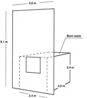
The smaller facility was a 2.4 m wide by 3.6 m deep by 2.4 m high room with the front wall extended to 6.1 m in height and 3.6 m in width (Fig. 1). The exposed wall was
Fig. 1 Smaller test facility used to study heat transfer to exterior wall.
concrete blocks covered with 13 mm thick non-combustible board (density: 770 kglm3). Wood cribs, distributed uniformly over the floor area and representing a fire load of 25 kgIm2 were used as fuel. The cribs were made of 41 mm
x 41 mm pine sticks. Ventilation was provided by the
window opening only, with the opening dimensions selected so that the intense burning phase lasted for 15 to 20 min. In the first and the third tests, a 1.13 m square window opening was used. In the second test, a tall narrow (1.50 x 0.69 m) window opening was used. The dimensions of the window in the second test were selected to provide approximately the same ventilation to the fire as that provided by the window in the first and the third tests, following the Fujita (1 958) equation:
where:
M
-
rate of mass inflow of airK
-
constant A,-
window area h-
window heightMeasurements of the total heat flux density were taken on the centre-line of the wall, at 0.25 m, 1 .O m, 1.75 m and 2.5 m above the top of the window. The transducers used were water-cooled Medtherm 64 Series, range 200 kWIm2, 100 kW/m2, 100 kW/m2, and 50 kW/m2 respectively. lrradiance was measured using air-purged, water cooled radiometers (Medtherm 64 Series with sapphire window, range 100 kW/m2) installed on the centre- line of the wall at 0.25 m and 1.0 m above the top of the
window. Condensation on the transducers was prevented by supplying cooling water at a temperature of 50°C, from a thermostatically controlled circulator. Sooting of the radiometer windows occasionally occurred despite the air purge system. Readings were discarded when a radiometer was found after the experiment to have its window sooted.
Figure 2 shows heat transfer data collected during the first test. The solid line represents total heat flux density at 0.25 m above the top of the window. The dashed line shows radiant heat flux density as measured by the air-purged radiometer installed adjacent to the total heat flow transducer. The third line shows convective heat flux density calculated as the difference between the total heat flux density and the radiant flux density. The maximum recorded values of the total and the radiant heat flux densities were 90 kWIm2 and 51 kWlm2 respectively. The maximum calculated convective heat flux density was 41 kW/m2. The radiant heat flux density constituted approximately 60% of the total heat flux density for most of the experiment. Figure 3 shows the heat transfer data obtained from the measurements taken during the second test with the tall
0 5 10 15 20 25 30
Time, min
Fig. 2 Heat transfer at 0.25 m above window, wood crib fire, 1.13 m square window.
-
0 5 10 15 20 25 30Time, min.
Fig. 3 Heat transfer at 0.25 m above window, wood crib fire, 0.69 m wide by 1.5 m wide window.
narrow window, at 0.25 m above the top of the window. The radiant portion of the total heat flux density was similar to that recorded in the first test. The convective portion however, was much higher in this test than in the first test and briefly exceeded 90 kWIm2. The total heat flux density exceeded 100 kW/m2 for a substantial portion of the experiment. Only one test was conducted using each window opening and the statistical significance of the above data is not known at this time.
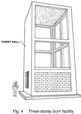
Another series of three wood crib fires was conducted using the larger facility. That facility (Fig. 4) consisted of a three storey (10.3 m) high reinforced concrete frame, a burn room located on the ground floor, and a concrete block front wall covered with 13 mm thick non-combustible board (density: 770 kg/m3). The burn room consisted of a reinforced concrete floor, concrete block walls and a precast
Fig. 4 Three-storey burn facility.
concrete panel ceiling. The walls and ceiling were covered on the room side with 25 mm thick ceramic fibre insulation. The floor was covered with 57 mm thick fired clay paving stones. The inside dimensions of the burn room were 5.95 m wide, 4.4 m deep and 2.75 m high. One 1.37 m high
x 2.60 m wide window opening was provided in the front
wall of the burn room. This was the only opening in the room boundaries.
A 25 kglm* fire load comprising six wood cribs made of 41 mm x 89 mm pine studs was used. The cribs were uniformly distributed in the burn room.
The total heat flux density to the wall was monitored by four water-cooled heat flow transducers, the same units as those used in the smaller facility, installed in the wall with their sensing faces flush with the outer surface of the wall. The transducers were located on the vertical centre line, at 1.0 m intervals, starting at 0.5 m above the window opening. Two radiometers were also installed in the wall but their readings are not reported because of sooting of the radiometer windows. Figure 5 shows heat flow data collected in one of the tests, at various heights above top of the window.
Time, min
Fig. 5 Total heat transfer to wall above window, wood crib fire, three-storey burn facility, 2.6 m wide by 1.37 m high window.
A series of experimental fires using propane gas as the fuel was carried out in order to study the impact of heat release rate, in conjunction with window opening dimensions, on heat transfer to the exterior wall. The experimental fires were conducted using the three-storey test facility equipped with four 3.8 m long linear propane diffusion burners, spaced equally along the width of the room and elevated 0.6 m above the floor. The propane mass flow rate was manually controlled and monitored by a hot wire type flowmeter. The total heat flux density was measured at four levels at 1.0 m intervals, starting 0.5 m above the window.
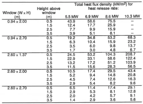
Data collected in the propane gas fires are summarized in Table 1. The table shows time-averaged total heat flux density for different heat release rates, heights above the window, and window dimensions. The heat release rate was calculated from the gas supply rate assuming complete combustion.
Figure 6 shows a section of the data assembled in Table I, the total heat flux density measured at 0.5 m above the top of the window opening versus the rate of heat released in the fire, for five different window dimensions. The heat transfer to the exterior wall depends on both the window opening dimensions and the heat release rate. The low, wide window opening (2.6 m wide by 1.37 m high) had the highest heat transfer for every heat release rate except 5.5 MW. Video records showed that with this heat release rate the smallest window had a substantial flame issuing from the window while the bigger windows allowed combustion to be completed within the burn room.
Figure 7 shows another section of the data assembled in Table 1, an example of heat transfer versus height above the window, for one window (2.6 m wide x
1.37 m high) and for different heat release rates.
It is interesting to see how the data obtained in wood crib fires compare with the data obtained in propane fires. The comparison has to be approximate since the fuel consumption rate was not measured in the wood crib fires. Assuming, after Heselden (1 968), that 50% of the wood was consumed at a steady rate over the fully developed period, one can estimate that the heat release rate in the fires conducted using the three storey facility was 6 f 0.5 MW. For this heat release rate and a 2.6 m wide and 1.37 m high
Table 1. Variation of time-averaged total heat flux density with heat release rate, height above window, and window dimensions. Data derived from propane gas fires in 3-storey burn facility.
Total heat flux density (kWlm2) for Height above heat release rate:
Window
IW
x HI window(m)
(m)
5.5 MW 6.0 MW 8.6 MW 10.3MW
0.94 x 2.00 0.5 43.9 58.6 75.5
..-
1.5 12.4 17.7 25.9
--
window opening (used in the wood crib fires), the heat flux density at 0.5 m above the window can be estimated at 36 f 8 kWlm2 for the propane fire compared with 45 kWIm2 for the wood crib fire (Fig. 5). A propane fire produces somewhat lower exposure than the wood crib fire at the same heat release rate. This can be explained by the lower emissivity of the propane flame. As Fig. 6 shows, the difference can be easily compensated by increasing heat release rate (gas flow) in the propane fire.
-
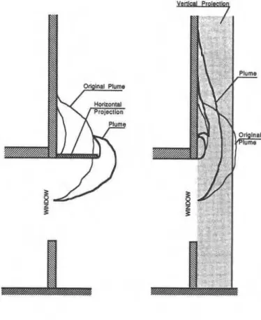
One test was conducted to assess the effects of the facade geometry on heat transfer to the facade. The test was conducted using the smaller burn facility. The window opening was 1.13 m square and the fuel load comprised wood cribs (24 kgIm2) made of 41 mm x 41 mm pine sticks. During the test, two types of projection were applied to the exterior wall. One was a horizontal panel, 1.22 m deep andHEAT RELEASE RATE (MW) HEIGHT ABOVE WINDOW (m)
Fig. 7 Variation of heat transfer to wall with height above Fig. 6 Variation of heat transfer to wall at 0.5 m above window and heat release rate, 2.6 m wide by 1.37 m
2.44 m wlde, attached to the wail immediately above the window openlng. The second was a pair of 1.22 m deep vertical panels perpendicular to the wall, anached along both sides of the window opening. Figure 8 shows the
changes to the plume due to the presence of these projections.
Fig. 8 Window plume changes due to application of projections.
Figure 9 shows readings of the total heat flow transducers installed on the wall at various levels above the top of the window. It is clear, despite the scatter of the data, that the horizontal projection offered substantial protection for the wall above the window. This data supports the assumptions proposed by Harmathy (1974). He stated that a device, called a flame deflector, could protect windows from fire plumes issuing from storeys below. On the other hand, Fig. 9 shows that the vertical projections increased heat transfer to the facade. They restricted lateral air entrainment to the plume causing a vertical extension of the combustion zone within the plume. Although no gas velocity measurements within the plume were taken, the video recording seems to indicate an increased vertical velocity of the gases within the plume which may increase the convective heat transfer.
Accuracv of Heat Transfer M e w e m e m
The transducers used for measurements of both total and radiant heat flux density were circular foil, Gardon-type gauges. These gauges were originally developed for the measurement of radiant heat flux density and their typical bias is within 3% of full scale (American Society for Testing and Materials (ASTM) Standard E 51 1-73, 1988) when used as radiometers. However, when used as convective or total heat flux transducers, they tend to underestimate the "cold wall" flux. The "cold wall" flux can be defined as a flux to an isothermal wall at a temperature low in comparison to the heat source. The error increases with the increase of convective heat flux absorbed by the gauge and can be as high as 25% for purely convective flux at the maximum output of the gauge (Striegl and Diller, 1984 and Borell and Diller, 1987).
The heat flux absorbed by the foil is conducted to the perimeter of the foil, where the foil is attached to the body of the gauge. The radial heat flow creates temperature differential between the centre of the foil and its perimeter, which is typically 220°C for the maximum output of the gauge (ASTM Standard E 51 1-73). The increase of the foil temperature causes a decrease of the air-to-foil temperature difference and, consequently, decrease of convective flux to the gauge. Measurements of radiant flux are usually not affected by the increased foil temperature. Measurements of purely convective flux can be taken using a gauge calibrated in convective flows or the error can be estimated using procedures developed through the theoretical analysis of the gauge (Borell and Diller, 1987). For combined radiative and convective flux measurements using a single gauge, no method exists at this time to calibrate the gauge or to accurately estimate the error.
An approximate correction of the convective component of the flux can be estimated under the following assumptions:
the "cold walln temperature is given
the convective heat transfer coefficient is constant across the foil
the ratio of radiant flux to convective flux is known the temperature of the convective source is known
The ratio of the convective "cold wall" flux to that received by the gauge can be estimated as the ratio of the temDerature differential between the source and the "cold Time, min. wall", to the average temperature differential between the source and the foil. Knowing the correction factor for the Fig. 9 Variation of heat transfer to wall at different heights convective flux, a correction factor for the total heat flux can above window, caused by wall projections. be calculated taking into account the share of the convective Horizontal projection (flame deflector) was applied flux in the total flux.
between 10 min and 13 min, vertical projections were applied between 15 min and 18 min.
The gauges used for the measurements reported in this work were chosen so that most of the readings were lower than 50% of the gauge's rating. At 50% of the gauge's rating, the temperature of the centre of the foil is 110°C higher than the temperature of the gauge's body. Assuming paraboloidic distribution of the foil temperature, which is true for pure radiant flux (Gardon, 1953) and approximate for mixed flux, the average foil temperature is equal to the arithmetic average of the temperature of the edge of the foil and the temperature of the centre of the foil. Assuming further that the gauge's body temperature is 100°C (accordingly to the standard, boiling of the cooling water must not occur), the average foil temperature at the output of 50% of the gauge's rating can be assessed at 155°C. Measurements of air temperature taken at 5 cm from the foil varied from 150°C to 950°C with majority of the readings being close to 650°C. Assuming the source temperature for the convective flux to be 650°C and the "cold wall" temperature to be 100°C, one can calculate the ratio of the "cold wall" convective heat flux density to that received by the gauge to be 1 .I 1. The 1 1 % correction of the convective flux translates into 4.4% correction of the total flux, assuming 40% share of the convective flux in the total flux.
It is worth noting that in practical applications of the reported measurements, the wall temperature is usually higher than the "cold wall" temperature assumed in the above estimate. No correction is needed if the wall temperature is equal to the average foil temperature.
MODEL OF HEAT TRANSFER TO WALL SURFACE
The model described below is a modified version of the model developed by Law (1978) as a design guide for exterior structural steel elements. Law's model estimates flame projection and flame temperature for given compartment dimensions, quantity of combustibles, window dimensions, and ventilation conditions ("natural" draft versus forced ventilation). Based on the flame geometry and temperature, the model estimates both radiant and convective heat transfer to columns and beams that may be located outside the building envelope.
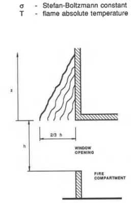
To adapt the model for the calculation of heat transfer to the building facade, the procedures describing radiant and convective heat transfer were modified. The original radiant heat transfer procedure assumed constant flame thickness, which is a simple and conservative assumption. This assumption results in an unrealistically abrupt change of the calculated heat transfer in the area near the top of the flame. The modified procedure assumes a triangular shaped flame, as shown in Fig. 10. Local emissivity of the flame was calculated using the extinction coefficient recommended by Law (1 978):
where:
b
-
extinction coefficient, 0.09 ft-I in U.S. units or 0.3 m-1 in S.I. unitsh
-
flame thicknessz
-
vertical distance from top of window The radiant heat flux density was calculated as follows:where:
o
-
Stefan-Boltzmann constant T-
flame absolute temperatureWINDOW O P E N I H a
Fig. 10 Assumed shape of emerging flame
The original convective heat transfer procedure was modified to eliminate the dependence of the procedure on the shape of the receivers (beams and columns), and to correlate the calculated and the experimental values of the convective heat transfer. The convective heat flux density can be expressed as:
where:
T
-
fire plume temperature Tw-
wall temperaturea
-
convective heat transfer coefficient A general form of the convective heat transfer coefficient was taken as:where:
R
-
rate of burning A,-
area of window k-
empirical factorIn deriving equation (5) it is assumed that the mass velocity within the window plume is proportional to the ratio
of burning rate to the window area. This equation is a more general version of the corresponding equation used by Law
(1 978) in her model. The empirical factor k was determined by correlating the calculated convective heat flux density with the results obtained from measurements in the wood crib fires conducted in the smaller burn facility (using the data shown in Fig. 2 and Fig. 3). The numerical value of the factor k depends on units of the other quantities involved, as shown in Table 2.
Table 2. Empirical factor k, for different unit systems
K m2 kglmin kWIm2 0.01 3
K m2 MW kWlm2 0.030
OR ft2 Iblmin BtuIft2 min 0.1 0
Figure 1 1 shows the calculated and the measured (in two different experiments) vertical distribution of the total heat flux density for the wood crib fires in the 3-storey burn facility. The calculated curve is conservative but shows the same trend as the measured values. Being conservative, the difference between the calculated and the measured values is acceptable from the fire protection engineering point of view.
HEIGHT ABOVE WINDOW (m)
Fig. 1 1 Measured and calculated heat transfer to wall above window, wood crib fires in three-storey burn facility, 2.6 m wide by 1.37 m high window.
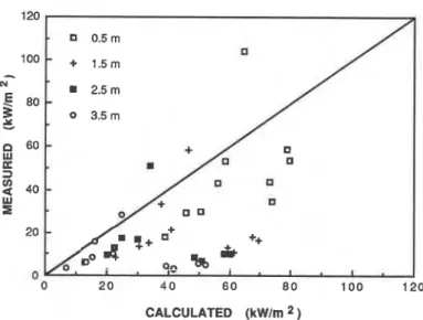
Figure 12 compares the calculated and time- averaged measured total heat flux density for the propane gas fires conducted in the 3-storey burn facility. The calculated values are conservative for the majority of the
data points; however, the overall correlation Is rather poor. One reason for the large scatter of data points may be that
some
of the propane fires had heat release rates differentfrom those obtained in the fire tests used to develop the model. To test this hypothesis, another correlation (Fig. 13) was prepared. The data points in this graph are limited to those representing fires with heat release rate within f20% of a "normal" fire. The "normal" burning rate was defined using Thomas' (1 974) equation:
" -
0 2 0 40 60 8 0 100
CALCULATED (kWIm 2,
Fig. 12 Measured and calculated heat transfer to wall above window, propane fires.
where:
At
-
total area of room boundaries less the window areah
-
window heightD
-
room depthW
-
room widthThe above equation is appropriate for S.I. units. The heat release rate was calculated from the burning rate using
15 MJIkg as the heating value of wood. The improved correlation shown in Fig. 13 indicates that the model works better for this narrow range of burning rates.
The data in Fig. 13 are categorized by the height above the window. The results show that the model predicts heat transfer in the area immediately above the window better than far above the window.
0 2 0 4 0 6 0 8 0 100 120
CALCULATED (kwlm 2 )
R = 0.18 11
-
exp[ -0.036 1 (A, hlE)]}(D
~ ) 1 1 2 ( 6 ) Fig. 13. Measured and calculated heat transfer to wall above window, fires with heat release within +20% of "normal" rate.CONCLUSIONS REFERENCES Fire venting through a window can create a severe
thermal exposure to a facade. The fire heat release rate, window dimensions and facade geometry are equally important factors influencing the level of thermal exposure to the exterior wall.
The exposure increases with increasing heat release rate. The exposure increases faster than the heat release rate because an increasing portion of combustion takes place outside the fire compartment, in the vicinity of the exposed facade.
Large windows allow more fuel to be burned inside the fire compartment than the small windows, thus decreasing the exterior fire plume temperature and height of the flaming portion of the plume. The ratio of the window opening height to its width controls the shape of the plume. Tall windows tend to project flames away from the facade, decreasing the thermal coupling of the flames with the facade and causing relatively low thermal exposure to it.
The model can be used to calculate heat transfer from a window fire plume to a building facade, provided the fire involves mostly combustibles burning at a moderate rate, such as wood furniture and other relatively thick objects made of charring materials. The model needs to be improved in order to be applicable to fires involving large quantities of faster burning materials, such as plastics and thin combustible panels.
ACKNOWLEDGEMENT
The following IRC personnel were instrumental in conducting the experiments and processing the data for this project: Donald W. Carpenter, Jack E. Berndt, George P. Crampton, Michael S. Ryan, and Victor A. Fortington.
American Society for Testing and Materials, 1988, "Measurements of Heat Flux Using a Copper-Constantant Circular Foil, Heat-Flux Gage," 1988 Annual Book of ASTM
Standards, Standard E 51 1-73 (Reaproved 1982), Section 15, Vol. 15.03, pp. 355-360.
Borell, G. J., and Diller, T.E., 1987, "A Convection Calibration Method for Local Heat Flux Gages," ASME
Journal of Heat Transfer, Vol. 109, pp. 83-89.
Fujita, K., 1958, "Characteristics of Fire Inside a Non- combustible Room and Prevention of Fire Damage," Report 2(2), Japanese Ministry of Construction, Building Research Institute, Tokyo.
Gardon, R., 1953, "An Instrument for the Direct Measurement of Intense Thermal Radiation," The Review of
Scientific Instruments, Vol. 24, No. 5, pp. 366-370.
Harmathy, T.Z., 1974, "Flame Deflectors," Building Research Note No. 96, Division of Building Research, National Research Council, Ottawa, Canada.
Heselden, A. J. M., 1968, "Parameters Determining the Severity of Fire," Paper in Joint Fire Research Organization Symposium No. 2, Behaviour of Structural Steel in Fire, HMSO, London.
Law. M., 1978, "Fire Safety of External Building Elements-The Design Approach," AlSC Engineering
Journal, Second Quarter11 978.
Striegl, S.A., and Diller, T.E., 1984, "The Effect of Entrainment Temperature on Jet Impingement Heat Transfer," ASME Journal of Heat Transfer, Vol. 106, pp. 27-33.
Thomas, P. H., 1974, "Fires in Model Rooms: CIB Research Programmes," Building Research Establishment Current Paper CP 32/74, BRE, Borehamwood.