Publisher’s version / Version de l'éditeur:
Vous avez des questions? Nous pouvons vous aider. Pour communiquer directement avec un auteur, consultez la première page de la revue dans laquelle son article a été publié afin de trouver ses coordonnées. Si vous n’arrivez pas à les repérer, communiquez avec nous à [email protected].
Questions? Contact the NRC Publications Archive team at
[email protected]. If you wish to email the authors directly, please see the first page of the publication for their contact information.
https://publications-cnrc.canada.ca/fra/droits
L’accès à ce site Web et l’utilisation de son contenu sont assujettis aux conditions présentées dans le site LISEZ CES CONDITIONS ATTENTIVEMENT AVANT D’UTILISER CE SITE WEB.
Laboratory Memorandum; no. LM-2004-21, 2004
READ THESE TERMS AND CONDITIONS CAREFULLY BEFORE USING THIS WEBSITE.
https://nrc-publications.canada.ca/eng/copyright
NRC Publications Archive Record / Notice des Archives des publications du CNRC :
https://nrc-publications.canada.ca/eng/view/object/?id=698c1eba-bfcc-4f0c-a4e2-742f716e6e66 https://publications-cnrc.canada.ca/fra/voir/objet/?id=698c1eba-bfcc-4f0c-a4e2-742f716e6e66
NRC Publications Archive
Archives des publications du CNRC
For the publisher’s version, please access the DOI link below./ Pour consulter la version de l’éditeur, utilisez le lien DOI ci-dessous.
https://doi.org/10.4224/8895331
Access and use of this website and the material on it are subject to the Terms and Conditions set forth at Buoyancy Engine Construction and Design for an Underwater Glider
National Research Council Canada Institute for Ocean Technology Conseil national de recherches Canada Institut des technologies oc ´eaniques
Laboratory Memorandum
LM-2004-21
Buoyancy Engine Construction and Design for an
Underwater Glider
B. Skillings
August 2004
DOCUMENTATION PAGE
REPORT NUMBER LM-2004-21 NRC REPORT NUMBER --- DATE August 2004 REPORT SECURITY CLASSIFICATIONUnclassified
DISTRIBUTION Unlimited TITLE
BUOYANCY ENGINE CONSTRUCTION AND DESIGN FOR AN UNDERWATER GLIDER AUTHOR(S)
Ben Skillings
CORPORATE AUTHOR(S)/PERFORMING AGENCY(S)
Institute for Ocean Technology, National Research Council (NRC-IOT) PUBLICATION
---
SPONSORING AGENCY(S)
Institute for Ocean Technology, National Research Council (NRC-IOT) IOT PROJECT NUMBER
42_891_10
NRC FILE NUMBER ---
KEY WORDS
buoyancy engine, pitch, roll, submersible control,
underwater glider, autonomous underwater vehicle, AUV
PAGES 15 FIGS. 18 TABLES 2 SUMMARY
This report details the construction of a buoyancy engine. (See Janes, Nick. Design of a Buoyancy Engine for an Underwater Glider VM1 L121 LM-2004-13 for a previous study.) There is an introduction to the significance of a buoyancy engine to underwater glider technology as well as a description of some existing gliders. The following section describes the design challenge: to build a vertically translating programmable buoyancy engine capable of diving to maximum depth of 20 m. After identifying drawbacks of the original design, design changes were made and construction was undertaken. There was a setback in the choice of an ABS pipe as a structural member; however, a solution was identified and built.
Conclusions and future work end this memorandum, identifying lessons learned and a path for further development.
ADDRESS National Research Council Institute for Ocean Technology Arctic Avenue, P. O. Box 12093 St. John's, NL A1B 3T5
National Research Council Conseil national de recherches Canada Canada
Institute for Ocean Institut des technologies Technology océaniques
BUOYANCY ENGINE CONSTRUCTION AND DESIGN
FOR AN UNDERWATER GLIDER
LM-2004-21
Ben Skillings
SUMMARY
This report details the construction of a buoyancy engine. (See Janes, Nick. Design of a Buoyancy Engine for an Underwater Glider VM1 L121 LM-2004-13 for a previous study.) There is an introduction to the significance of a buoyancy engine to underwater glider technology as well as a description of some existing gliders. The following section describes the design challenge: to build a vertically translating programmable buoyancy engine capable of diving to maximum depth of 20 m. After identifying drawbacks of the original design, design changes were made and construction was undertaken. There was a setback in the choice of an ABS pipe as a structural member; however, a solution was identified and built. Conclusions and future work end this memorandum, identifying lessons learned and a path for further development.
TABLE OF CONTENTS
1.0 INTRODUCTION...1 2.0 DESIGN CHALLENGE ...3 2.1 Design Constraints ...3 2.2 Design Fundamentals...3 2.3 Previous Design ...43.0 DESIGN MODIFICATIONS AND CONSTRUCTION ...6
3.1 Construction Overview...7
3.2 Connecting Pipe Solution Development ...9
4.0 FINAL DESIGN...12
5.0 CONCLUSIONS AND FUTURE WORK ...14
REFERENCES ...16 APPENDIX A
Buoyancy Engine Budget ... A-1 Buoyancy Engine Part Masses...A-2
APPENDIX B - COMPONENT ORDERS AND INSTRUCTIONS
APPENDIX C - MATLAB CODE AND CENTRE OF GRAVITY…
APPENDIX D - DRAWINGS
LIST OF FIGURES
Figure 1-1: Slocom Thermal Glider... 1
Figure 1-2: Seaglider... 2
Figure 2-1: Nick Janes’ winning design concept... 4
Figure 2-2: Nick Janes’ design of a buoyancy engine. ... 5
Figure 3-1: Original design modification. ... 6
Figure 3-2: PVC Parting on the lathe... 7
Figure 3-3: The nearly complete diaphragm mount. ... 7
Figure 3-4: Drilling the piston lightening holes... 8
Figure 3-5: Trimming to length, facing and boring of the connecting pipes... 8
Figure 3-6: Strap clamps – modified hose clamps... 9
Figure 3-7: Concentricity and parallelism issue ...10
Figure 3-8: Pipe geometric inspection – measuring FIM. ... 10
Figure 3-9: Illustration of the diaphragm alignment piece ...11
Figure 3-10: Parallelism and FIM readings ...11
Figure 3-11: Surface table inspection. ... 12
Figure 4-1: All of the major components...13
Figure 5-1: Simple concept of the pitch and roll assembly. ... 15
Figure 5-2: Conceptual design for the IOT development glider... 15
LIST OF ABBREVIATIONS AND SYMBOLS
AUV...Autonomous Underwater Vehicle ABS...acrylonitrile butadiene styrene FIM ...full indicator movement
NRC-IOT ...National Research Council Institute for Ocean Technology PVC...polyvinyl chloride
1.0 INTRODUCTION
Underwater gliders are a relatively new development in Autonomous Underwater Vehicle (AUV) design. Henry Stommel and Doug Webb are credited with envisioning the
underwater glider concept. Stommel imagined a world ocean observing network based on “a fleet of small neutrally-buoyant floats called Slocums” that “migrate vertically through the ocean by changing ballast, and they can be steered horizontally by gliding on wings at about a 35 degrees angle… During brief moments at the surface, they transmit their accumulated data and receive instructions . . . Their speed is generally about 0.5 knot.” (Rudnick 2004, 48) The significance of this inspiration to oceanographers is clear when the frequently exorbitant cost of ship time for small research budgets are compared to cost of available gliders. Although the initial cost is upwards of $75,000, these
lightweight, reusable AUVs can be launched from a small boat with no special equipment for weeks at a time.
One of the first companies to pursue Stommel’s vision was the Webb Research Corporation in East Falmouth, Massachusetts. They currently have one commercially available glider on the market today, the Slocom Electric and one under development, the Slocum Thermal. As the informing names indicate, alkaline batteries power the Electric glider and a thermal energy harvesting engine powers the Thermal. The major advantage of the Thermal glider is the massive gain in range and duration due to the harnessing of environmental energy. Compared to the information in Table 1-1, the Electric glider has a range of 30 days over 1500 km and a maximum depth of 200 m.
Figure 1-1: Slocom Thermal Glider
http://www.webbresearch.com
Table 1-1: Slocom Thermal Specifications
• Weight: 60 Kg • Endurance: 5 years
• Hull Diameter: 21.3 cm • Range: 40000 km
• Vehicle Length: 1.5 meters • Navigation: GPS, dead reckoning, altimeter
• Depth Range: 4 - 2000 meters • Sensor Package: Conductivity, Temperature, Depth
• Speed, projected: 0.4 m/sec horizontal • Communications: RF modem, Iridium satellite, ARGOS
Another underwater glider, Seaglider, has been developed at the University of Washington (Seattle) by the Applied Physics Laboratory and the School of
Oceanography. A unique feature is an isopycnal hull- the glider volume compresses at a rate to match the small changes in seawater density as it dives.
Figure 1-2: Seaglider: visible components include the antenna at the bottom of the image as well as the
pressure vessels
http://www.apl.washington. edu/projects/seaglider/sum mary.html
Table 1-2: Seaglider Specifications
• Weight: 52 Kg • Endurance: 1-6 months
• Hull Diameter: 30 cm • Range: 6000 km
• Vehicle Length: 1.8 meters • Navigation: GPS, dead reckoning, magnetic
• Depth Range: 1000 meters • Sensor Package: Conductivity, Temperature, Depth
• Speed, projected: 0.25 m/sec horizontal • Communications: Iridium satellite, AMPS cellular
At the heart of any glider today is the ballast device – the buoyancy engine. By either changing the mass or volume of the submersed vehicle it changes the direction of the net buoyant force. If the vehicle is negatively buoyant, the glider sinks and is horizontally directed by the wings as water flows over them. Pitch is usually controlled by a sliding mass to adjust the centre of gravity and thereby creating a pitching moment. A rolling moment is generated by a rolling mass and with the wing lift and drag it turns like it possessed a conventional rudder. On these saw-tooth dives, information such as temperature, salinity and microscopic plant count can be gathered.
2.0 DESIGN
CHALLENGE
The National Research Council’s Institute for Ocean Technology (NRC-IOT)1 is developing an underwater glider for research in dynamics and control. As part of the development process, the first objective is to build a vertically translating programmable buoyancy engine capable of diving to maximum depth of 20 m. In a previous study (Janes 2004), the best design out of five candidates was determined. In this chapter we present a brief overview of the previous work as well as additions for this report.
2.1 Design Constraints
1) Size
• Design will fit in a standard 1 m long, 10 cm pipe.
• Selected as a down scaled version of the Slocum Glider, as it also has a 10:1 length to diameter ratio.
2) Depth
• Buoyancy engine module should be designed to operate to a depth of 20 m • Selected because the depth of the testing facility, the Towing
Tank2, is 7 m. This gives a comfortable 2.9 factor of safety. 3) Centre of Gravity and Centre of Buoyancy Position
• For a vertically translating variable buoyancy vehicle, it is clear that the centre of buoyancy must be above the centre of gravity for a stable dive path.
4) Mass of vehicle must be the same as the volume of water it displaces. • Necessary condition for a neutrally buoyant body. This allows for a
modification in volume that enables a change in the direction of the net buoyant force.
2.2 Design Fundamentals
Disregarding the dynamic effects of drag or the added mass due to the blunt cylinder accelerating in water (for more information on the analytical dynamic information, see Janes), there are only two basic methods of changing the net force acting on the vehicle:
1) Change the volume while maintaining constant mass. 2) Change the mass while maintaining constant volume.
1
NRC-IOT was previously known as the Institute for Marine Dynamics (NRC-IMD). 2
The Towing Tank is a rectangular tank 200m (656 ft) in length, 12m (39 ft) in width and 7m (23 ft) in depth capable of wave and wind generation. Models are towed through still water or waves by a carriage spanning the width of the tank. Model rigging is facilitated by two trim docks and a moveable overhead crane (4000 kg).
There are several methods used to accomplish this direction change in the net force. The second method has no variations, as it can only be accomplished by dropping weight. Clearly this is not an option for a long range, lightweight vehicle capable of hundreds of dives over its mission. This method, however, is used by most submersibles to recover the vehicles in an emergency situation.
The first method has many variations. It can be a pump to move oil from an internal to external bladder; it could be a release of air into a bladder by means of a chemical reaction or by a release of compressed air; or it could be an actuator driven piston to move a diaphragm. Of the five design concepts considered in a previous study (Janes
2004), an electromechanically driven actuator pushing a rolling diaphragm was selected as the best candidate. It was selected because of the quick response time, projected medium cost of the vehicle and considered the easiest to manufacture.
Figure 2-1: Nick Janes’ winning design concept: linear actuator and rolling diaphragm.
2.3 Previous Design
The previous design had a 1 m long 10 cm diameter PVC pipe encasing all of the major components. The linear actuator is an eight inch stroke UltraMotion® Digit with a NEMA 23 stepper motor and an Applied Motion 3540M controller. The rolling
diaphragm is a 80 mm long, 95 mm diameter Dia-Com Type D-300-300. Inside the pipe was a 70% partial vacuum to keep the diaphragm attached to the piston without the use of adhesives. The other components (diaphragm fastener, diaphragm mount, piston,
actuator mounting plate, mounting plate supports, electronics tray and end cap) were to all be custom made in-house. For construction, the end cap, rolling diaphragm mount and the linear actuator mount were all to be bonded to the interior of the pipe by means of PVC glue.
Figure 2-2: Nick Janes’ design of a buoyancy engine.
With respect to this design, there were two serious drawbacks:
1) It required assembly with PVC glue
• PVC glue sets in approximately five minutes. This does not leave enough time to accurately position parts deeper within the pipe.
2) The design was not modular
• Due to the permanently bonded construction of the assembly, it was not possible to access all components after assembling the system. (i.e. rewiring of the actuator)
These two issues needed to be addressed in a design modification. In addition, more detailed drawings were required to begin construction.
3.0 DESIGN
MODIFICATIONS AND CONSTRUCTION
To deal with both of these design issues, two changes were made. First, a mid-body section was inserted into a newly split section of pipe to address issue two, and second, strap clamps were to run axially along the hull to pull the unit together to address issue one. Although the strap clamps are not visible in Figure 3-1, all of the main components are visible. (See Figure 3-6 on p. 9 for strap clamps and Appendix D for drawings.) All of the components (linear actuator, rolling diaphragm, ect.) that were considered for the
previous design were used in the design modification. In addition, the basic cylindrical form was kept the same. All of the purchase orders are in Appendix B.
End Cap
Connecting Pipes Mid- Body Section
Piston
Diaphragm Nut Actuator
Diaphragm Mount
Figure 3-1: Original design modification.
Further to these changes, there were design modifications of the diaphragm nut and mount to ensure proper threading detail and proper specifications for the end cap fitting locations. Keeping the mass of each component as small as possible was a guiding design principle in order to leave extra room for further development such as the mass of a computer, batteries and sensors for the final vertically translating vehicle. See
Appendix A for the mass of each component and the available “ballast tolerance.” Note that the manufacturing tolerances were taken into account - regardless of each feature size when assembled the ballast requirement for neutral buoyancy will fall within these extremes.
3.1 Construction Overview
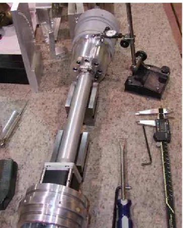
From the required drawings, a materials list was produced. All of the parts were machined in the machine shop at IOT. There were, however, some manufacturing challenges. Specifically, the required tolerances of the radial face groove on the diaphragm mount needed a special lathe bit ground; see Figure 3-3. Figures 3-2 to 3-6 are a selection of construction photographs.
Figure 3-2: PVC Parting on the lathe – notice the PVC streamer coming off the tool.
Figure 3-3: The nearly complete diaphragm mount – specially ground lathe bit is being used to produce radius.
Figure 3-4: Drilling the piston lightening holes – center-drilling operation.
Figure 3-5: Trimming to length, facing and boring of the connecting pipes.
Unfortunately, the connecting pipe machining became problematic. ABS pipe was used instead of PVC because of availability. Upon receipt of this material, it was clear that the pipe was significantly bowed and elliptical. In addition, there was not a lathe available with a five inch through bore (the hole through the lathe spindle) making it necessary to mount the pipes to right-angle plates on a milling machine, align the average center of the pipes and size the bore with a micro boring head; see Figure 3-5. It was during this operation that it became suspect that ABS pipe had the desired mechanical properties.
Figure 3-6: Strap clamps – modified hose clamps. Two lengths are used for the diaphragm and electric end pipes.
After the initial assembly of all the parts, it was evident that there was a significant flaw in the choice of materials– one that should have been obvious in the previous design. In order for the unit to operate properly, it is required that the diaphragm mount be parallel and concentric with the axis of the actuating cylinder within 0.025 inch. During the course of the pipe investigation, it was found that the pipe was on average 1/16 of an inch per foot bowed; had a minor inside diameter of 3.963 in and a major inside diameter of 4.020 in; and the FIM (full indicator movement) when measuring of the pipe between size averaged plugs was between 0.030 in and 0.040 in. (Size averaging means taking the average of the inside elliptical diameter, turned a plug with that average diameter and pressing it in.) Compounding the pipe bow problem was the manufacturing operation. Due to the bow, the ends of the pipe could not be machined parallel. Adding to the alignment problem was the strap clamp arrangement. It was possible to pull the pipe away from a position by tightening or loosening the clamps. (See Figure 3-7)
3.2 Connecting Pipe Solution Development
After several attempts at finding a solution, it was determined that ABS is too weak a material to be held for a machining operation without a significant change in dimension – it is, after all, intended for a sewer pipe. Therefore, a machinist has to contend with a material that will flex significantly for work piece holding. As a result, even though the pipe may be machined round and to the correct dimensions, it will inevitably flex and return to its elliptical shape.
Figure 3-7: Concentricity and parallelism Issue – the maximum gap is about 0.180 in compared to 0.042 in at the minimum.
Figure 3-8: Pipe geometric inspection – measuring FIM.
It was finally concluded that a new approach would be needed. Using the actuator tube as a datum, a new alignment piece was designed and machined. As can be seen in the figure below, the alignment piece uses a hose clamp collet to compress and hold the diaphragm
Figure 3-9: Illustration of the diaphragm alignment piece.
Figure 3-10: Parallelism and FIM readings of the forward assembly.
mount concentrically to the actuator tube. From the surface table inspection
measurements taken as illustrated in Figure 3-10 and 3-11, the form tolerance errors are now solved - the Diaphragm Mount is within 0.007 inches FIM. By assembling the buoyancy engine such that the gap between the diaphragm mount outside diameter and the mid-body section is slightly longer than the pipe (0.010 to 0.025 in), the diaphragm mount is now concentric.
Figure 3-11: Surface table inspection.
Although the alignment accuracy has significantly improved with the measures taken, the axial alignment of the piston due to the actuator manufacturer’s ambiguous tolerance still needs to be addressed. Although the diaphragm mount is now sufficiently collinear to run true to the inside bore of the diaphragm mount, the piston rides at an angle relative to the axis of the actuator tube. However, the error is not sufficiently egregious to warrant an immediate fix.
4.0 FINAL
DESIGN
The final design drawings are in Appendix D. Due to lack of available time, the Alignment Piece and Actuator Hold-Downs are only provided as sketches. Although
these are not proper drawings, they do convey the geometric information.3 The final design weighs 6.84 kg within a 1 m long, 10 cm diameter cylinder. To meet the condition that the centre of gravity is below the centre of buoyancy position at all
actuator positions, a MATLab program was used (Appendix C). Missing from this code are the effects of the Alignment Piece, as the centre of gravity of this piece was not put into the code. (The code was written before the original design.) However, this was not added because the initial plot of the centre of gravity for all actuator positions was always below the centre of gravity. Given that the Alignment Piece position would only make the centre of gravity even farther below the centre of buoyancy, this work was not done.
As the displaced mass of water is approximately 9.72 kg compared to the mass of 6.84 kg, this 2.88 kg difference can be filled with 20 D cell batteries to give about 100 Wh. Although these batteries are not able to fit around the actuator tube because of lack of space (this would be ideal as it would shift the centre of gravity even further to the
bottom end) they are able to fit in an array of 4 in a cross pattern, five deep along the axis of the electronics end pipe.
Figure 4-1: All of the major components disassembled.
3
The Diaphragm mount, drawing 891_10BS01 has to be altered to accept the ¼ dowels at the base.
5.0 CONCLUSIONS AND FUTURE WORK
he mechanical aspects of the buoyancy engine are almost complete. Although full echanical drawings are not finished for the Alignment Piece and the Actuator Hold-owns, the geometric information is supplied. The following is a list of future work that
1) Pressure Testing of the Hull
e
2) Assemble and Program Electronic Components to Get the Unit Diving
3)
• Producing position, velocity and acceleration information for the vessel will be a first step in an optimization process.
4) Develop Co onvergence
Time to the desired De
• Set up a computer terminal such that the vehicle performance was outputted in real time performance plots to ensure that the vehicle performs to
expectations.
Further to these development goals, there are some specific recommendations for a future version of a buoyancy engine. Clearly, ABS pipe should not be used as a structural member. Instead, use the average of the major and minor diameter of the elliptical pipe and size the corresponding fittings to that diameter. The pipe would have to be pressed onto the matching bore, but this would significantly reduce the problems encountered in this design. In addition, the machined components could be reduced in mass, as the aluminum pieces are not fully engineered but designed from experience. There could also be a thermister installed in the electronics end to monitor the interior of the vehicle temperature to ensure that there are not over heating issues.
Perhaps the ntral
datum and construction platform. Just as the Diaphragm Mount was cantered with a new Alignm
giv ine
changes in the centre of buoyancy due to manufacturing.
For fut a
unit that is gine. It would be possible to add a pitch and roll control assembly around the actuator tube. A conceptual design is shown in F
T m D
needs to be done to fully develop the vehicle:
• Before any electronic components are put in the water, the vessel should b pressure tested to 270 Kpa. (Gauge pressure at 20 m depth plus the 70% internal vacuum)
Produce Position, Velocity and Acceleration Plots
most important design change would be to use the actuator tube as the ce
ntrol Interface and Control Algorithm to Optimize C pth
ent Piece, the Mid-Body section could be attached in a similar manner. This es the advantage of some axial movement in the sections to compensate for any f
ure work beyond the goals of this design challenge, it would be desirable to have more powerful than simply a buoyancy en
igure 5-1. As the final version of this buoyancy engine (and perhaps it will be a
combin o developme
ati n with a pitch and roll control system) will be installed in the IOT nt glider, this unit may be the heart of this conceptual machine.
Figure 5-1: Simple concept of the pitch and roll assembly. Green square is a sliding and rotating mass on a plain bearing driven be a linear and rotary actuators (yellow).
Figure 5-2: Conceptual design for the IOT development glider. The cylinder in the middle of the hull represents the buoyancy, pitch and roll module. It may by a hybrid vehicle, as indicated by the green propeller.
References
APL University of Washington, Manufacturers of Seaglider: www.apl.washington.edu/projects/seaglider/summary.html
D. C. Webb, P. J. Simonetti, and C. P. Jones. SLOCUM: An underwater glider propelled by environmental energy. IEEE Journal of Oceanic Engineering, 26(4): 447–452, October 2001.
Janes, Nick. Design of a Buoyancy Engine for an Underwater Glider. CISTI-IOT VM1 L121 LM-2004-13
J. Sherman, R. E. Davis, W. B. Owens, and J. Valdes. The autonomous underwater glider ”Spray”. IEEE Journal of Oceanic Engineering, 26(4)
Rudnick, D e echnology
Society Journal 38 (1): 48-59, Spring 2004
Stommel, H. 1989. The Slocum mission. Oceanography. 2:22-25.
Webb Research Corporation, East Falmouth, Massachusetts Manufacturers of Slocum: http://www.webbresearch.com
:437–446, October 2001
t al. 2004. Underwater Gliders for Ocean Research. Marine T
Buoyancy Engine Budget
$US Conversion: 1.34 $CDN
Note: All units in inches
Components Quantity Unit Cost Total Cost
Digit Linear Actuator 1 1259.60 1,259.60 Applied Motion Stepper Controller 1 348.40 348.40
Dia-Com Diaphragms 10 15.41 154.10 Dia-Com Setup Charge 1 703.50 703.50
Absolute Pressure Sensor 1 477.04 477.04 Absolute Pressure Transducer 1 155.44 155.44
Nickel Plated Cord Grip 5 6.70 33.50 Stainless Steel Button Head #10-24 x1/4 1 8.99 8.99 O-Ring Buna N 240 1 15.87 15.87 Quick Disconnect Socket 5 11.32 56.62 Quick Disconnect Plug 5 10.89 54.47
Components Total: $3,267.52
Materials List
Stainless St. 304 ROUND BAR: 1/2 DIA x 15 1/2 1 - 21.00
Al 6061-T6 ROUND BAR: 3 DIA x 3 1/2 1 - 10.00
ROUND BAR: 4 1/2 DIA x 2 5/8 1 - 40.00
PVC PIPE: 4 1/2 OD, 4 ID x 38 1 - 15.00 ROUND BAR: 4 1/2 DIA x 7 1/8 1 - 55.00
ABS PIPE: 4 DIA SCH 40 1 - 15.00
Nylon WASHER: 3 7/8 OD, 3 ID x 1/16 1 - n/c
Materials Total: $156.00
Special Tools
Radial Face Grooving Turning Tool 1 250.00 250.00
Special Tool Total: $250.00
Sub-Total: $3,673.52 Tax Rate: 15.00% Total: $4,224.55 A-1