Design of an Endoscopic Biopsy Needle with Flexural Members
ByStacy L. Figueredo
SUBMITTED TO THE DEPARTMENT OF MECHANICAL ENGINEERING IN PARTIAL FULFILLMENT OF THE REQUIREMENTS FOR THE DEGREE OF
MASTER OF SCIENCE IN MECHANICAL ENGINEERING AT THE
MASSACHUSETTS INSTITUTE OF TECHNOLOGY SEPTEMBER 2006
©2006 Massachusetts Institute of Technology. All rights reserved.
Signature of Author:
Department of Mechanical Engineering August 18, 2006 Certified by:
Alexander H. Slocum Professor of Mechanical Engineering Thesis Supervisor Accepted by:
Lallit Anand Professor of Mechanical Engineering Chairman, Department Committee on Graduate Students
Design of an Endoscopic Biopsy Needle with Flexural Members
byStacy L. Figueredo
Submitted to the Department of Mechanical Engineering on August 18, 2006 in Partial Fulfillment of the Requirements for the Degree of Master of Science
at the Massachusetts Institute of Technology
ABSTRACT
As a minimally invasive means of extracting a tissue sample from a patient, current endoscopic biopsy needles generally do not preserve tissue histology and often require multiple attempts to obtain a tissue sample. This paper presents an endoscopic biopsy needle with internal flexures that enable tissue to enter the hollow needle and then be severed from surrounding tissue when the needle is withdrawn. Using force-deflection and sample weight data from 10x scaled prototypes, variations of a flexural design captured 1.1 grams of a tissue phantom on average, as compared to wedge-type designs that averaged of 0.7-0.8 grams. Peak entrance forces for the flexure design were lower than for both wedge and extended wedge designs, and resistance forces were higher upon needle extraction. A low-angle 15-degree feature produced lower entrance resistance and larger exit resistance compared with 30 degree, 45 degree, and 60 degree features, which is desirable when retaining tissue. Manufacturing of a 1x scale prototypes, using a grinding and laser cutting process, suggested that flexural features could be produced in current endoscopic biopsy needles, but changes to the beveled cutting tip would first have to be made before flexural elements could be tested on actual liver samples.
Thesis Supervisor:
Professor Alexander H. Slocum
Table of Contents
ABSTRACT ... 3 List of Figures ... 7 List of Tables ... 9 Acknowledgements ... 11 Chapter 1 ... 13 INTRODUCTION... 13 Chapter 2 ... 16 BACKGROUND... 162.1 Current Biopsy Needle Design Overview... 17
2.2 Endoscopic Procedure ... 20
2.3 Ultrasound Imaging ... 23
2.4 Anatomy and Biomechanics of the Gastrointestinal Tract and the Impact on Needle Design 24 2.5 Pathological Examination... 27
2.6 Establishing Functional Requirements and Design Parameters... 28
Chapter 3 ... 30
PRELIMINARY DESIGN ANALYSIS... 30
3.1 Performance of Existing Needle Types ... 30
3.2 General Cutting Strategies... 32
3.3 Evaluation of Needle Concepts... 37
Chapter 4 ... 40
FLEXURAL NEEDLE DESIGN PRINCIPLES ... 40
4.1 Flexure Deformation... 40
4.2 Parameter Variation... 42
Chapter 5 ... 45
PROCEDURE AND TESTING OF 10X SCALE NEEDLES ... 45
5.1 Needle Variations ... 45
5.2 Scaling of Needle Tip Prototypes ... 47
5.3 Tissue Phantom for 10x Scale Needles... 47
5.4 Force Displacement Testing Setup ... 49
5.5 Force Displacement Data Results ... 50
5.6 Sample Mass Comparisons for Design Type and Feature Angle ... 55
5.7 Puncture Forces for Design Type and Feature Angle ... 56
5.8 Entrance and Exit Slope for Design Type and Feature Angle ... 58
5.9 Visual and Audible Reference of Intended Operation ... 61
Chapter 6 ... 63
FINITE ELEMENT ANALYSIS ... 63
6.2 Windowing Flexure Parameters to Prevent Buckling of Needle Wall... 65
6.3 Optimization of Flexure Shape to Prevent Plastic Yielding ... 66
Chapter 7 ... 69
1X SCALE NEEDLE MANUFACTURING PARAMETERS ... 69
7.1 Springback Compensation and Testing ... 69
7.2 Needle Tip Integration with Bulk Needle Design... 72
7.3 Bevel Angle Sensitivity ... 74
7.4 1x Scale Needle Prototype Manufacturing ... 76
7.4.2 Production of Ground Needle Tips ... 76
7.4.2 Laser Cutting of Flexures into the Needle Wall ... 78
Chapter 8 ... 80
DISCUSSION CONCLUSIONS AND FUTURE WORK... 80
8.1 Positive Developments in the Design of an Improved Endoscopic Biopsy Needle... 80
8.2 Limitations of the Current Design and Testing of 1x Scale Prototypes... 81
8.3 Conclusion... 83 8.4 Future Work... 83 Appendix A ... 86 Appendix B... 87 Appendix C ... 89 Appendix D ... 90 Appendix E... 91 Appendix F... 92 Appendix G ... 93 Appendix H ... 95 References ... 96
List of Figures
Figure 1: Echotip Ultra Ultrasound Needle and typical needle components labeled.
Source: Cook Endoscopy--- 19
Figure 2: Room set-up and patient positioning for endoscope. --- 20
Figure 3: Typical components of an endoscope with components labeled. (Source: eyedesignbook.com) --- 21
Figure 4: Endoscope with typical components labeled 1. Sheath, 2. Ultrasound transducer, 3. Optic lens, 4. Steel needle, 5. Distal flexible end of the endoscope. (Source: Endosonograpy.dk)--- 21
Figure 5 A, Technique of fine needle aspiration (FNA); B, corresponding endoscopic ultrasonography image. Source: Johns Hopkins Medical Institutions Digestive Disease Library --- 22
Figure 6: Endoscope with Ultrasound Transducer --- 23
Figure 7 Echogenicity of a dimpled needle.--- 24
Figure 8: Major components of the gastrointestinal system--- 25
Figure 9: Layers of the Gut Wall . Source: Gray’s Anatomy --- 28
Figure 10: Sample of sketches from brainstorming session of tissue capture possibilities. --- 33
Figure 11: An experiment testing biopsy needle strategies: (a) an end-cutting strategy, (b) side-cutting strategy. --- 34
Figure 12: Cutting Strategies and First-Order Estimates of Cutting Force --- 35
Figure 13: Experiment testing end-cutting biopsy needle concepts. --- 37
Figure 14: Needle Concepts a) Barbed Needle Concept, b) Flexural Needle Concept, c) Tweezers Needle Concept--- 38
Figure 15: Prototype of three needle concepts and typical sampling results. a) Barbed needle, b) Flexural-member needle, c) Tweezers-type needle, d) Typical results using gelatin phantom. --- 39
Figure 16: Cross-section of single flexure with dimensions labeled. --- 41
Figure 17: Gelatinous samples obtained from the DOE orthogonal array. Each column is labeled with the critical parameter values used for that experiment: (i) angle, (ii) number of flexures and (iii) flexure thickness. --- 43
Figure 18: Needle Prototype Cross-Sections--- 46
Figure 19: Needle prototype setup for force-displacement measurements--- 49
Figure 20: Cross section of gelatin phantom after coring test of 4x scale needles. --- 50
Figure 21: Force displacement curve of pre-pierced site showing slope from friction of outer wall, which is estimated using a linear best-fit approximation.--- 51
Figure 22: Force displacement curve for a flexural design with characteristic drop during needle puncture and sharp decrease in force during tissue tearing. Peaks from piercing and design features are also present.--- 51
Figure 23: Force displacement curves for wedge needle prototypes for 30, 45, and 60 degree feature angles. --- 52
Figure 24: Force displacement curves for extended wedge needle prototypes with 30, 45,
and 60 degree angles. --- 53
Figure 25: Force displacement curves for flexure needle prototypes 15, 30, long 15, and long 30 degree angles. --- 54
Figure 26: Average sample mass (g) vs. design type with a sample size of 10. Standard deviation noted above each data set. --- 55
Figure 27: Average sample mass (g) versus feature angle (degrees) with a sample size of 10. Standard deviation noted above each data set. --- 56
Figure 28: Comparison of Design Type to Characteristic Peaks --- 57
Figure 29: Comparison of Feature Angle to Characteristic Peaks --- 58
Figure 30: Relationship between Feature Type and Characteristic Slopes--- 59
Figure 31: Comparison of Feature Angle to Characteristic Slope--- 60
Figure 32: Flexure deformation sequence while entering gelatin during test. a) Piercing b) Initial entrance c) Sample collected prior to withdrawal & severing. --- 62
Figure 33: Stress analysis in CosmosWorks of tapered flexure with 2N applied load and 15 degree bend on tapered section.--- 64
Figure 34: Forces and restraints on needle design with worst-case dimensions for needle buckling--- 65
Figure 35: Buckling analysis estimate of failure for 1st buckling mode with deformation scale of 0.46 and load factor of 9.07 --- 66
Figure 36: a) Leaflet Geometries that were tested using FEA, b) COSMOSWorks FEA of typical flexures showing yielding in red for a geometry without stress relief --- 67
Figure 37: Drawing of final flexure concept after FEA analysis. (units in mm) --- 68
Figure 38: 304 Stainless steel stress-strain curves.--- 70
Figure 39: Bending die for flexure springback estimation. --- 71
Figure 40: Springback samples of 0.178mm thickness 304 stainless steel showing average springback of 13 degrees from an initial 17.2 degree bend. --- 71
Figure 41: Bevel angle of needle tip. --- 74
Figure 42: Test setup of beveled needle piercing liver tissueusing a TA.XTPlus Texture Analyzer. --- 74
Figure 43:Puncture force of 22-degree and 30-degree bevel needle blanks --- 75
Figure 44: Needle Tip Grinding Process (Left to Right, Top to Bottom) Measure length, Rough cut, Clamp using vice, Grind bevel, Grind flat end, Measure length, De-burr, Hone tip, and Resulting needle.--- 77
Figure 45: Image of needle tip prototype after processing. --- 78
Figure 46: Laser cut features on a 19gauge (1.06mm) needle with a kerf width of 0.05mm.--- 79
Figure 47: Alternate needle tips that could be used in endoscopic needle design (left) cone biopsy needle with beveled inner surface, (center) gardner type needle with multiple points, (right) Silverman dual-point tip. Source: Popper and Sons--- 84
List of Tables
Table 1: Mechanical properties of the gastrointestinal system of an average adult.
(Compiled from Yamada). 8... 27
Table 2: Functional Requirements of Endoscopic Biopsy Needle ... 29
Table 3: General Description of Cutting Strategies... 32
Table 4: Design of Experiments 3x3 Orthogonal Array of Parameters Results... 44
Table 5: Entrance and exit characteristics of sample needles. (** indicates data not available)... 61
Table 6: Needle tip integration strategies ... 73
Acknowledgements
Margo Figueredo is not here today to read this paper. She died in April of 2005 of pancreatic cancer, after smiling and cheering everyone up about her own illness. My aunt was one of my biggest supporters throughout my years MIT and she was one of the few people who would understand how this project helped me to not feel so helpless about her being gone. I hope that, in some form, the work in this paper can help others who are going through a similar struggle as hers.
I would like to thank Professor Alex Slocum for being an advisor that will help with the fun parts of a project and the frustrating parts. His graduate class, 2.75 Precision Machine Design, was where I was first presented the problem of working on an improved endoscopic biopsy needle, and where I first started working with other students on a possible solution. Ever optimistic, always realistic. Thanks so much for your advice.
Another close advisor for this Project was Dr. William Brugge of Massachusetts General Hospital, who volunteered many hours of his time to giving me advice and design ideas for the project. As an expert in the fields of gastroenterology and endoscopy, Dr. Brugge’s expertise was critical to understanding the problem and scope of the project.
Initial research on the endoscopic biopsy needle design was conducted with a great team of students during the MIT course 2.75 Precision Machine Design: Andrew Carvey, Bill Fienup, Barry Kudrowitz, and Jacob Wronksi. Maureen Lynch, our administrative assistant who keeps this side of the building from collapsing under a pile of paper, was always around to help. I appreciate the help of Professor Mary Boyce and Asha Balakrishnan for frequent use of their lab and assistance with the TA.XT setup and Massachusetts General Hospital for use of their facilities and excellent staff. Vendors in
the medical industry are mentioned throughout the paper that were particularly helpful during this project and should be recognized for their excellent service.
Of course, this project could not have been completed without the financial support and technical experience of The Center for Integration of Medicine and Innovative Technology (www.cimit.org). CIMIT has supported this project with funding provided from the U.S. Army Medical Acquisition Activity (USAMRAA) under cooperative agreement no. DAMD 17-02-2-0006. The content of this information does not necessarily reflect the position or policy of the Government, and no official endorsement should be inferred. (Although I hope they like it.)
Chapter 1
INTRODUCTION
Gastrointestinal (GI) cancers are the most common malignancy in the United States, and cancer of the gastroesophageal junction is the most rapidly increasing cancer in the
US.1 The vast majority of GI cancers are diagnosed with endoscopic instruments that
travel through the esophagus to obtain high resolution video and ultrasound images. Along with ultrasound imaging techniques, tissue-sampling procedures, known as biopsies, provide vital information about abnormal cellular development and tissue composition. According to a National Health Statistics study taken in 1996, over 1.2
million endoscopic biopsies are performed in the United States each year2. Even with
this level of testing, the 5-year survival rates for gastrointestinal cancers remains relatively low. The five-year survival rate for a tumor less than 2cm and confined to the
head of the pancreas at the time of resection is approximately 20%.3
With most forms of cancer, an early and accurate diagnosis is critical for improving survival statistics. In the case of gastrointestinal cancers, endoscopic tissue biopsy is a key tool for early determination of the histological and cytological makeup of a lesion or grown. Current endoscopic biopsy designs may use a forceps mechanism or a hollow coring needle to obtain a tissue sample from a suspicious growth. These devices range in size from 14-gauge to 23-gauge hollow needles and larger scoop-shapes, but for GI
procedures, all must be deployed through the small inner channel of an endoscope. Both of these current designs often require multiple attempts to acquire samples for cytological and histological analysis of tissues. This can be because the sample is not large enough (either as a mass measurement or in length), or because the tissue organization has been damaged during retrieval. In either case, such a result may delay or prohibit proper diagnosis.
This inability to reliably obtain a tissue presents the problem with current endoscopic biopsy tools and with biopsy needles in particular. If a sample of tissue is not retrieved the first time a needle is inserted into a patient, the doctor may have to create additional tissue puncture sites, which introduces unnecessary patient trauma. Current endoscopic biopsy procedures also require sedation, which is in some way trauma to the patient on top of the wound created by tissue removal. If an adequate sample is not retrieved during the initial endoscopy procedure, anesthesia and additional procedures would be necessary. Of course, the financial costs of repeat procedures, more needles used, additional equipment time, and increased loading on staff, are absorbed by both hospitals and the patient. Given the improvements in care, accuracy in diagnosis, and cost savings that could be achieved by investigating biopsy needles, it was determined that an assessment of current technology and new design for clinical use would be worthwhile.
As described in detail, this project focuses on the development a safe and reliable endoscopic biopsy that improves tissue sampling success rates and preserves the histology of tissue samples. In order to increase the sampling output of a coring biopsy needle, researchers investigated several methods to improve the design. Active and passive methods of obtaining tissue samples were compared from both the end and the side of a cylindrical needle. After studying the overall means of sampling, methods of increasing shear force to overcome the force required to cut tissue were developed. A specific method for cutting and retaining tissue using a device with low entrance resistance but high exit resistance in order to cut and retain the tissue sample was
developed. Such a design allows tissue to enter the cavity of the needle when it is cut, but prevents the sample from exiting to such an extent that it is separated for the bulk of the suspect tissue and can removed from the body for testing purposes.
The final design employed a set of flexures that were angled into the needle. As this needle pierces tissue, its flexures open and allow a sample into the hollow needle tip. Upon extraction of the needle, forces normal to the needle axis cause the flexures to close, and shear forces sever the sample from surrounding tissue preserving a core sample inside the needle tip. This concept was tested using 10x scale stereolithographed needles and a gelatin tissue phantom to determine optimal feature dimensions. These results were used to prototype 1x scale 19-gauge stainless steel needle tips with laser cut features.
This paper presents the development of the aforementioned biopsy needle from functional requirements to final design. Included are an overview of existing technology, and the constraints of the biopsy procedure on a needle design, as well as the functional requirements and design parameters of the device. Early concept development, which was crucial in quickly pinpointing a solution, is presented, along with some of the basic mechanical principles underlying the flexural design. Finite element analysis of critical components is given where necessary to ensure soundness of the design, as well as some of the basic scaling that went into needle prototypes. Data from 10x needle tests of flexures compared to similar design features is presented as support for the flexural design over other geometries, as well as for determination of optimal parameters. Manufacturing and testing of 1x prototypes is given as an accurate assessment of the device design. A discussion of results presents needle performance as compared to the original device requirements. Finally, concluding remarks about future manufacturing possibilities and references to alternative materials are given.
Chapter 2
BACKGROUND
As with most precision devices, medical products in particular, a significant amount of background research must be conducted to understand an underlying problem that is not necessarily in a primary area of engineering. This allows an engineer to obtain enough information about an area to develop functional requirements for a device - measures of success that ensure desired results, which generally involves accurate and safe the implementation of the product. In order to develop an improved endoscopic biopsy tool, existing endoscopic biopsy needle designs and their capabilities are described in this section. The current endoscopic biopsy procedure is described to explore how this sequence of events may allow for design improvements. Ultrasound treatments are briefly described to introduce some design features that may be beneficial to needle tip visibility. Anatomical data for the gastrointestinal system, which affects needle dimensions and strength requirements, is also discussed. An overview of pathological tissue samples is given to understand why histological information is important to a sample, as well as how this diagnostic step affects device design. Finally, this background information is tabulated into the functional requirements for a proposed design.
2.1 Current Biopsy Needle Design Overview
Exactly how “the business end” of a needle obtains a sample though is relatively flexible from a design standpoint. To discover the design opportunities for such a device, we will see how a typical needle is designed, its major components, what the core purpose of these features are, and later, how such components can be redesigned to improve the reliability of an endoscopic needle biopsy.
The needle assembly has several components (see Figure 1). First, the sheath of the needle is a thin flexible plastic tube with a low coefficient of friction such that the long metal needle can slide inside it without sticking. The sheath serves a dual purpose of protecting the interior of the endoscope and preventing the needle from cutting into tissue before reaching the biopsy site. It would most likely be an extruded part during the manufacturing process due to its uniform cross-section and thin wall.
Along the inside of the sheath lies the actual coring needle, which is a hollow ultra-thin wall tube of 304 or 316L stainless steel. The needle is slightly longer than the endoscope (138mm to 140mm) and is sharpened to a beveled point. Typical medical bevels between 18 and 45 degrees exist depending on the application (tissue coring, fluid extraction, fluid injection, etc.). The needle gauge determines the outer diameter of the needle and may vary from a large 16-gauge needle to an extremely fine 23-gauge depending on the application. The wall thickness for any specific needle gauge outer diameter determines both the buckling strength of the needle as well as the maximum coring area, and is commercially available in wall thicknesses as thin as 0.0508mm (0.002in). Ultrasound features such as dimples or polymer coatings may be added to the needle tip as well, as explained in Section 2.3. This needle may perform the sampling operation using either a side cutting mechanism or the core of a hollow needle tip. Although, current models are exclusively made of stainless steel, some background
research has shown a potential for high flow length polymers in the production of needles.
Another feature of an endoscopic biopsy needle assembly is a removable stainless steel stylet that runs down the interior of the hollow needle. The stylet is a thin rod that prevents a needle from collecting tissue before reaching the desired sample site. By blocking the hollow inner needle channel and extending past the pointed needle with its beveled tip, the stylet ensures there is no unintended tissue puncture. It is also used to push tissue out of the needle once a sample has been gathered. This component can be seen in Figure 1.
A multifunctional handle is the final component in the needle assembly. Although dependent on the manufacturer, the controls typically work in such a way that the needle slides relative to the sheath. This handle is used by a doctor or technician to control the extension and location of the needle, as well as to provide the cutting action if passive or to trigger the device if active. A location to insert and remove the stylet is accessible from the handle area, and for aspiration needle, a syringe can be attached to provide suction. As an example, the handle of a Cook® endoscopic biopsy needle with the syringe attachment is shown in Figure 1b and Figure 1c.
Although improvements to all components ultimately provide the best overall improvements to the endoscopic biopsy needle design, the focus of the needle design for the purpose of this research will be the needle itself. This more than likely will affect the design of the control handle, sheath, and stylet, but is considered a secondary to the needle shape.
a)
b)
c)
Figure 1: Echotip Ultra Ultrasound Needle and typical needle components labeled. Source: Cook Endoscopy
2.2 Endoscopic Procedure
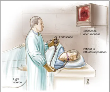
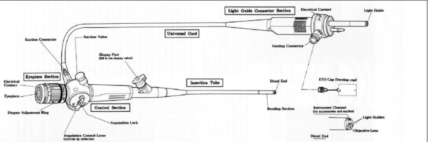
Exactly how a biopsy needle travels to a lesion in the body is another important aspect of the design, which can be described by analyzing the endoscopic biopsy procedure (Figure 2). A typical endoscope can be thought of as a semi-flexible tube, with a control section that allows the doctor to bend the endoscope head (Figure 3). On the head of the endoscope are an ultrasound device, the opening of an air or liquid flushingchannel, and the opening of the channel used for biopsy tools and other instruments (Figure 4). For the first step of an endoscopic biopsy, the endoscope is introduced through the mouth and is carefully guided via the esophagus, into the stomach, and then through the gastrointestinal system to the general area of the lesion using a small camera on the end of the tool (Figure 2). The flushing system clears the way for viewing the area and can prepare for the sampling step.
Figure 2: Room set-up and patient positioning for endoscope. Source: Johns Hopkins Medical Institutions Digestive Disease Library
Figure 3: Typical components of an endoscope with components labeled. (Source: eyedesignbook.com)
During the next step of the procedure this ultrasound device is used to image the subsurface of the site and some of the organs that lie on the other side of the
gastrointestinal wall, which helps to determine the exact site of a tumor or growth. After the endoscope is in place, a biopsy needle, such as the design we are proposing, is passed through the interior channel of the endoscope. The channel allows for the safe passage of the needle, which exits
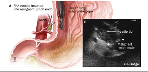
the head of the endoscope by approximately 3cm. Once the needle is inserted into the endoscope, the cutting section of a biopsy needle pierces tissue and retains a sample (Figure 5). While a doctor views the subsurface image using ultrasound, this procedure is repeated until an adequate amount of tissue has been obtained or until the limits of acceptable patient trauma has been reached.
Figure 4: Endoscope with typical components labeled 1. Sheath, 2. Ultrasound transducer, 3. Optic lens, 4. Steel needle, 5. Distal flexible end of the endoscope. (Source: Endosonograpy.dk4)
Figure 5 A, Technique of fine needle aspiration (FNA); B, corresponding endoscopic ultrasonography image. Source: Johns Hopkins Medical Institutions Digestive Disease Library
The endoscopy procedure and endoscope design enforce some constraints on the design of a needle biopsy device, such as overall size and shape. A needle must fit inside the endoscope and be long enough to reach a lesion. This needle must be able to cut tissue while maintaining its own structural integrity and ensure an acceptable level of medical safety. These are general assumptions that can be made for any sort of endoscopic tool.
2.3 Ultrasound Imaging
Once an endoscope is visually positioned in the general area of a suspected problem area, ultrasound imaging is used to gather information about the location of organs and tissue through the stomach and intestinal walls. This is accomplished using a small ultrasound transducer on the head of an endoscope that transmits a pulse of 2-5MHz for abdominal
diagnosis.5 The characteristic impedance of tissue
echoes back to the transducer, allowing a technician to see a rough image of surrounding tissue. Ultrasound imaging offers advantages such as no ionizing radiation or contrast material, minimal patient cooperation, real time imaging and detailed images of the relatively inaccessible pelvic region.
Disadvantages include a limited depth of penetration and low spatial resolution, although
recent developments in 3D ultrasound imaging are promising. 6
Figure 6: Endoscope with Ultrasound Transducer
Source: Johns Hopkins Medical Institutions Digestive Disease Library
From a design perspective, an endoscopic biopsy needle must be compatible with current ultrasound techniques by appearing in such imaging without distorting the view of
surrounding tissue.
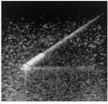
Echogenicity, the ability of an
object to be seen by ultrasound or the relative brightness of an object under ultrasound, is determined primarily by an object causing interference with ultrasound pulses. This occurs
when objects have features of the same dimension as the incoming wave. A biopsy needle design may often have small features on the tip to increase its visibility under ultrasound compared to surrounding tissue. This may be done with a 150 grit blast to
roughen the surface (Popper and Sons37), by coating the surface with a polymer that has
small bubbles encapsulated within its coating, or with other features of the same scale. When designing new needle geometry, it would be useful to ensure that the design can use one of these processes or that the design itself may improve visibility.
2.4 Anatomy and Biomechanics of the Gastrointestinal Tract
and the Impact on Needle Design
In order to understand the functional requirements of an endoscopic biopsy needle, it is necessary to investigate the environment in which such a device will operate. The ability of a needle to successfully obtain tissue samples will depend on its interactions with human tissues. Differences in geometry and material characteristics of tissue
Figure 7 Echogenicity of a dimpled needle. Source: Relative Ultrasonographic Echogenicity of Standard, Dimpled, and Polymeric-coated Needles, JVIR, March 20007
throughout the gastrointestinal system pose a significant challenge to the design. Moreover, tissue parameters inherently vary from individual to individual, and the diagnosis of abnormal tissues suggests that sample tissue characteristics may fall outside of the expected range even when normal patient variations are considered. Despite such a challenge, it is useful to understand something of the general anatomy and mechanical properties of the gastrointestinal tract that relate to the endoscopic procedure.
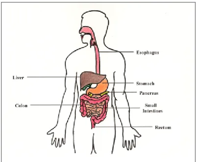
Figure 8: Major components of the gastrointestinal system
Looking at the basic function and size of tissues, the esophagus is a muscular tube, approximately 24cm long and 1.2 to 2.5cm in diameter, which transports food from the
pharynx to the stomach 8, and limits both the minimum length and maximum diameter of
an endoscopic tool. To prevent accidental tearing, which is common in endoscopic
procedures 8,9, it is useful to know the average wall thickness of 4.8mm laterally and 3.8
mm posteriorly.9 Following a small opening of the esophagus into the stomach, called
the cardiac region, an endoscope would enter into the stomach itself. The stomach can range in volume 30mL for an infant, to 1500mL for an adult and maintains an extremely acidic pH of 1.5-2 in order to break down food so that nutrients can be absorbed through the intestines. The acidic environment limits the type of material that can be used for a
biopsy tool to corrosive-resistant materials, such as 300 series stainless steel. The volume of the stomach and the angle of entry require a small radius of curvature to access all areas of the stomach wall.
Once an endoscope is positioned within the stomach, a core biopsy needle would pierce through the stomach wall to obtain samples of nearby organs. The liver, which lies in the upper right of the abdominal cavity and important in breakdown of materials in the blood, is often sampled to evaluate its epithelial cells, which make up most of the organ
structure. 10 The pancreas, which is the largest digestive gland (12 to 15 cm long in
adults), is responsible for secreting enzymes that break down lipids, and proteins. According to Gray’s Anatomy, “the spleen consists of a large encapsulated mass of vascular and lymphoid tissue situated in the upper left quadrant of the abdominal cavity
between the fundus of the stomach and the diaphragm.”11 A core needle biopsy of the
kidneys and other organs can also be performed using an endoscope depending on the organ’s location within the body.
Because the endoscopic needle biopsy procedure often requires piercing through the stomach lining as well as the organ or interest, it is important to note the tissue cutting properties of organs. Mechanical properties of tissue can vary widely within the gastrointestinal system, and from patient to patient, making proper cutting force
determination very difficult. Yamada’s Strength of Biological Materials12, which provides
tensile properties such as ultimate tensile strength, ultimate percent elongation, and tensile breaking load for many tissues in the body. Where data is human data is scarce, estimates based on bovine and porcine experiments provide reasonable estimates of tissue
properties for some internal organs18. Data from Okamura et al has noted puncture forces
for bovine liver from 1N to 3N, and preliminary puncture tests for 19-Gauge needles estimated 0.1N to 1N (Appendix A) An abbreviated table of relevant data adapted from Yamada is shown in Table 1.
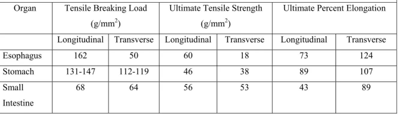
Table 1: Mechanical properties of the gastrointestinal system of an average adult. (Compiled from Yamada). 8
Organ Tensile Breaking Load (g/mm2)
Ultimate Tensile Strength (g/mm2)
Ultimate Percent Elongation Longitudinal Transverse Longitudinal Transverse Longitudinal Transverse
Esophagus 162 50 60 18 73 124 Stomach 131-147 112-119 46 38 89 107 Small Intestine 68 64 56 53 43 89
2.5 Pathological Examination
A biopsy is characterized by the removal and examination of tissue, cells, or fluids
from the living body13. From these pieces of information, doctors can determine if the
sample tissue is typical of that organ or potentially cancerous. To perform reliable chemical tests and to observe cells under a microscope, a minimum amount of tissue
(approximately 15mm long and 1mm in diameter) is required.14 While the details of how
pathologists analyze tissue are complicated, the basic understanding of what they need from a sample is not. Doctors use biopsy samples to analyze the cellular composition of tissue and, in the case of a core needle biopsy, the structure of the tissue. Further information about the histology, the structural organization of cells, can be studied if a sample is preserved in the same volumetric configuration as originally within the body, which is possible with core biopsy needles but is often destroyed with aspiration of the sample. At the same time, other than extracting a group of cells, a biopsy should not alter the physical or biological characteristics of the sample, such as would happen in the presence of chemicals, abnormal temperatures, or if separated from the body for extended periods of time. A successful biopsy device would have to consider all of these requirements in addition to those that would allow it to travel through an endoscope.
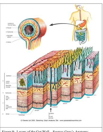
Figure 9: Layers of the Gut Wall . Source: Gray’s Anatomy
2.6 Establishing Functional Requirements and Design
Parameters
The endoscopy procedure and endoscope designs (Figure 4) place geometric constraints on the design of a needle biopsy device, such as the maximum needle diameter and minimum required sample length. The background information discussed in previous sections allowed the author to identify functional requirements; properties that a design would want to have in order to benefit the user. Design parameters, which quantify the functional requirements into engineering metrics, were also determined as shown in Table 2.
Table 2: Functional Requirements of Endoscopic Biopsy Needle
Functional Requirements Design Parameters
Fit within an endoscope to
reach desired sampling site. Minimum Endoscope channel diameter: 2.0mm (Hitachi 15) Endoscopic biopsy needle outer diameter 1.06 mm 19-Gauge (Brugge16)
Needle length: 138-140mm. (5cm past endoscope tube length) (Wilson-Cook 17)
Maximum bending radius approx. 5cm at tip. (Pentax Model) Capable of Cutting Human
Tissue (Stomach, Liver, Spleen, Kidney, Pancreas)
Cutting force greater than 5N. (Okamura18) Tip buckling force of >9N when extended.
Provide a sample of approximately 15mm in length. (Bravo19) Accurate and Reliable Cut only when at sampling site.
Preserve tissue histology and diagnostic quality of sample Target sampling success rate of 80% (Brugge16)
Interface/Feedback Compatible with standard controls procedure for similar devices. Tip visible under ultrasound.
Requirements for an improved core-sampling biopsy needle were determined both through observations of current needle shortcomings, as well as through interviews with
the potential customer20, which here is specified as the gastroenterologist that would use
an endoscopic biopsy needle for tissue examination. Because each biopsy procedure is costly and causes some patient stress, the overall aim of the needle was determined to be improved sampling reliability, measured as the average sample mass or length for a given needle gauge and wall thickness. These two measures, sample mass and sample length, would give the same sampling information because the combined gauge and wall thickness set the diameter of the sample. For a homogeneous sample of uniform density, the mass and sample length are proportional. Discussion with the customer set a target core sampling success rate of 80%. An overall 1.5cm desired sample length was set in order to provide an adequate amount of tissue for pathological testing. The needle diameter of 1.06mm (19 Gauge) would allow for standard endoscopic procedures. Of course, to ensure patient safety, the needle tip and any component of the needle cannot detach and become a threat to the patient during procedure. Finally, to allow for the doctor to maneuver the needle appropriately, the needle tip must be visible under ultrasound. With these basic requirements in mind, the following approach was taken to conceive, implement, and evaluate a core biopsy needle design.
Chapter 3
PRELIMINARY DESIGN ANALYSIS
In order to obtain a clearer understanding of our problem, initial tests were conducted with the biopsy needles presently used by doctors as well as other larger-scale methods of core sampling. This section describes the processes used to develop strategies, concepts, and, finally, an alpha prototype for proper tissue core extraction with desired histology.
3.1 Performance of Existing Needle Types
Initial design work focused on evaluation of current endoscopic biopsy designs and alternative strategies for improving tissue collection reliability. Current biopsy needles were classified into two main categories according to how they cut samples. End cutting needles punctured tissue using a sharpened hollow tube design to retrieve tissue. Side cutting needles use a sliding sheath to cut over an open side cavity in the needle. If either classification relied on suction to draw the sample out, the needle is termed an “aspiration needle.”
A Wilson-Cook Echo 19 core biopsy needle (end-cut), a Wilson-Cook Quik-Core (end-cut), and a Boston Scientific percutaneous biopsy needle (side-cut) were used to gain an understanding of current technology and the limitations of existing designs. Not meant to compare individual manufacturers, this qualitative comparison allowed for the assessment of overall end-cutting and side-cutting ability. Sampling from store bought
calf liver, the Boston Scientific™ non-endoscopic side cutter was the only needle that produced a core sample that would indicate the tissue histology. The Echo 19™byWilson Cook™ produced poor samples and several attempts were needed before a sample was extracted. The Quick Core™ also by Wilson Cook™ produced no samples. Although post-mortem refrigerated liver may have different tissue properties, this introductory assessment allowed for some understanding of each needle’s drawbacks.
Observations of the standard needles suggested that side-cut needles sometimes push tissue aside rather than cut through samples. Reasons can be lack of cutting speed, surface tension, and large radius of curvature of the tissue sample. End-cut needles that cored out a section of tissue were effective in cutting around
the circumference of a sample, but they had no reliable feature that could then sever perpendicular to the cylindrical core. This resulted in a cylindrical cut at the tissue site, but sometimes no sample in the needle (Table 3).
Figure3: left) Boston Scientific™ Easy-Core side-cutting biopsy needle (www.bostonscientific.com), upper right) Close up of Side cut needle, lower right) close up of end-cut needle
3.2 General Cutting Strategies
A focused brainstorming session was conducted in order to generate potential means
of acquiring tissue samples, as seen in Figure 10, with additional ideas shown in Appendix
B. Brainstorming also involved surveying aspects and methods of core sampling in fields outside of the medical industry. Topics that were explored include vibratory motion (to aid in endoscopic and tissue insertion), MEMS, ultrasonic cutting, suturing, and laser cutting. The resulting strategies were separated based on side-cut or end-cut classification, as previsouly mentioned. These two high-level groups were further subdivided according to the action associated with tissue capture: active (requiring some type of additional motion, moving component, or energy other than from the insertion/withdrawal motion) or passive (the action of inserting the needle into the tissue captures a sample without any additional effort, motion or action).
Table 3: General Description of Cutting Strategies
Side-Cut
Intended cutting Estimate of Actual Cutting
End-Cut
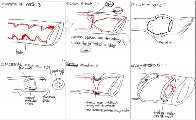
Figure 10: Sample of sketches from brainstorming session of tissue capture possibilities.
In order to select the optimal strategy to pursue, bench level experiments were performed. A qualitative method of comparing the extracted test samples was needed and so characteristics important characteristics were identified. These include the following:
• ease of motion for human interface (how well the doctor can control the device) • manufacturability
• reliability (the consistency an accurate sample with desired histology is extracted) • sample quality (how well the sample represents tissue histology)
In the bench level experiment, simple needle mockups, approximately 10x larger than the actual needle, were constructed from plastic tubes and tested on layered clay. The results were compared according to characteristics above and the end-cutting strategy was deemed easier to implement (Appendix C). The end-cutting strategy also tended to better preserve the layered clay histology when compared to the side-cutting strategy (see
Figure 6).
A passive means of extracting tissue samples was chosen based on size constraints and desire to limit complexity. Because an active method has moving parts or some energy source that could fail, they tend to be inherently less robust than passive methods. An active device would have to be consistently manufactured at less than 1mm in diameter to interact with the needle tip, and any bearing surfaces to support relative motion would have to be even smaller. A passive needle would have fewer components and no moving parts; could be safer for the patient and easier and less expensive to manufacture.
Figure 11: An experiment testing biopsy needle strategies: (a) an end-cutting strategy, (b) side-cutting strategy.
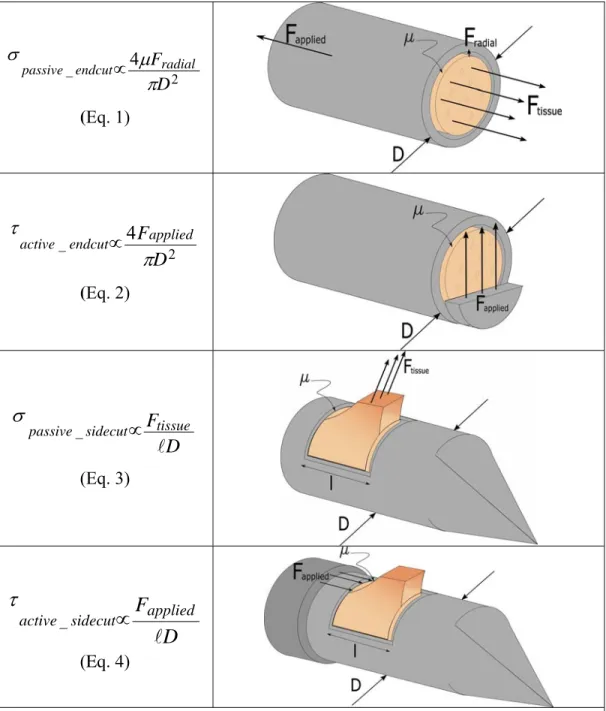
Following this design evaluation, first order estimates of the radial stresses and axial
stresses during sample gathering were used to compare the strategies as seen in Figure 12.
The difference between an active and a passive device was that the passive device used a radial force to sever tissue while the active devices would shear tissue. The end-cut
would have to sever through an area l*D, where the length (l) of the sample was l≈10D. In addition, passive methods would have to tear tissue in such a way that the tissue does not slip out of the needle before it is torn.
2 _ 4 D Fradial endcut passive π μ σ ∝ (Eq. 1) 2 _ 4 D Fapplied endcut active
π
τ
∝ (Eq. 2) D Ftissue sidecut passive l ∝ _σ
(Eq. 3)D
F
applied sidecut activel
∝
_τ
(Eq. 4)Figure 12: Cutting Strategies and First-Order Estimates of Cutting Force
from this estimate suggested the active end-cut had to shear the least to obtain a tissue sample. This was not surprising, since an end-cut would shear through a smaller cross section than a side-cut device that cuts along the length of the sample. This observation of an active device having a force advantage conflicted with bench-level experiments suggesting that passive devices would be easier to implement. A hybrid form of the end-cut design was introduced that would have no active components, but was capable of exerting force across the face of a tissue sample, such as was originally suggested by the active device equations. At the same time, it was realized that this force would only be advantageous when severing tissue, and could prevent a sample from entering the needle if present during the piercing stage of the biopsy action. Researchers hypothesized that a device that allowed tissue to enter the needle with little resistance but prevented tissue from exiting the needle by increasing resistance could act as a one-way valve to trap tissue. Concepts for an end-cutting needle built upon the idea of directional resistance feature.
A preliminary step in determining possible strategies involved analyzing the means in which a force is transmitted from the needle handle to the needle tip. The non-linear structure of the esophagus requires the endoscope and biopsy needle to trace a curved path and, therefore, the needle must then be flexible. With an assumed cylindrical shape, two motions were feasible: linear or rotational. In testing the feasibility of linear and rotational motion, the biopsy needle was bent in a similar manner as when inserted into a patient. The bend created a trivial increase in required force for linear motion. However, when attempting to revolve the bent needle, the 1+ meter length required substantial twisting (up to two revolutions) prior overcoming the frictional forces associated with the walls. This torsion-spring like behavior in the needle excluded revolving motions from possible cutting techniques. Although linear motion can be transformed into revolutionary motion, focus was directed towards pure linear motion to minimize complexity.
3.3 Evaluation of Needle Concepts
Following the end-cut strategy with differing entrance and exit resistances and a linear applied force, three directional biopsy tip concepts were developed and tested. Several types of passive end-cutting needles were machined using small metal tubing. The needles tested several sizes and cross-section shapes, but the critical variation was in the cutting mechanism. The cutting mechanisms can be classified as either internal barbs or crimped interference. Internal barbs created direct needle-tissue interference and relied on increase of friction to hold the tissue during extraction. The crimped interface used a smaller cross sectional area of the needle than the opening, resulting in tissue compression and increased wall friction during extraction. The crimped interface resulted poor tissue histology and this could be attributed to damage upon compression. As modeled, the barbed interface produced higher quality samples, as shown Figure 13; however, further testing was clearly needed.
Using the data from the machined metal needle experiment, the team decided on three concepts that had the greatest potential to retain samples reliably. In order to test these needle concepts, 4x scale parts were made using Selective Laser Sintering (SLS) and tested on a gelatinous phantom. The three concepts were as follows:
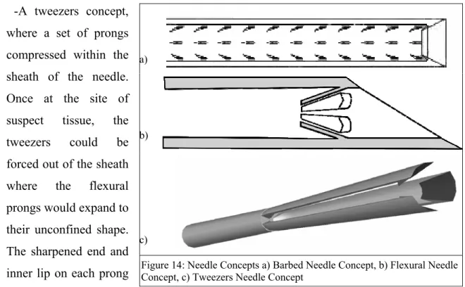
-A barbed needle with small internal features along the needle tip length that pointed radially inward. These barbs were also angled acutely into the needle such that a sample would be torn from the tissue when pulled out of the patient (Figure 14a). Inner features could be made by a punch method, with the outside needle wall covered by a plastic sheath to prevent tissue from escaping.
Figure 13: Experiment testing end-cutting biopsy needle concepts.
-A leaflet design consisting of a single ring of angled flexures that were intended to bend towards the needle wall so that tissue could enter when inserted into the patient. When pulled out of a lesion, these same flexures would bend towards the center of the needle to sever a sample within the needle. (Figure 14b)
-A tweezers concept, where a set of prongs compressed within the sheath of the needle. Once at the site of suspect tissue, the tweezers could be forced out of the sheath where the flexural prongs would expand to their unconfined shape. The sharpened end and inner lip on each prong
severed tissue and the device captured a sample as the tweezers were pulled back into the sheath. (Figure 14c)
The barbed needle prototype, containing four rows of 20 barbs, each with a 0.1mm diameter, was a simple design that required only a push pull motion. However, only a thin section of tissue was obtained. Also, although the concept successfully pulled out a core sample, this design did not ensure successful sampling because the tissue was often damaged upon removal from the needle.
The finger trap needle containing 6 flexible leaflets, illustrated in Figure 15b, also required only a push-pull motion to implement. Unlike the barbed needle, the core Figure 14: Needle Concepts a) Barbed Needle Concept, b) Flexural Needle Concept, c) Tweezers Needle Concept
a)
b)
samples were highly defined and it produced a sample more reliably. The volume of material was also, more intact as a core.
Positive results of the three-pronged tweezers concept, shown in Figure 15c, were that it cut the core of the tissue at the base and sealed the end of the needle using the principle of self-help. Unfortunately this design was difficult to operate, requiring three different motions that even the design team found to be confusing. Another disadvantage of the design was that the outward extension of the needle cut much more tissue than it captured, which was not desirable because it was more damaging to the patient. For these reasons, this design was considered to be less than optimal.
Three samples from the results of the SLS experiment discussed above are shown in Figure 15d. Tests revealed that the flexural design produced the highest quality samples, followed by the barbed needle concept. These observations, in addition to concerns regarding the manufacturing of small directional inner features, lead to the final concept of the biopsy needle with internal flexures.
Figure 15: Prototype of three needle concepts and typical sampling results. a) Barbed needle, b) Flexural-member needle, c) Tweezers-type needle, d) Typical results using gelatin phantom.
Chapter 4
FLEXURAL NEEDLE DESIGN
PRINCIPLES
Following a concept that uses flexures to retain a core of tissue, some basic assumptions about flexure shape and deformation must be assumed. If a load is applied by tissue to the flexure, it is assumed that this force is distributed evenly among flexures. The flexure itself can be modeled as a cantilevered beam of uniform rectangular cross section with a distributed load normal to the flexure. Although larger deflections would be expected for the flexure than standard cantilever equations, these estimates give a basis for finite element analysis (FEA) of more complicated flexure shapes, larger deflections, and more complex loading scenarios.
4.1 Flexure Deformation
To design the flexural features, critical design parameters were identified to be flexure thickness (h), number of flexures (n) and the angle between the flexure and the needle wall (θ). In addition, the needle material’s Young’s Modulus (E) was considered an important factor, but this could be addressed for metal needles or even plastic needles, at a later time. The flexure thickness h would be approximately the same thickness as the needle wall for a metal design and possibly thicker for a plastic needle. The flexure width b was approximately the circumference of the needle divided by the number of flexures at its base and would have to narrow as it approaches the center of the needle to
prevent interference. The length of the flexure l was limited to the product of half the inner diameter of the needle and sin (θ). The tip deflection d of the flexure (assuming small deflections and a distributed load) was calculated from these values where the angle of the flexure changes depending on the direction of the applied force.
Figure 16: Cross-section of single flexure with dimensions labeled.
The normal force on a flexure when tissue enters the needle can be estimated from the normal force applied by the tissue divided by the number of flexures. This is multiplied by the sine of the flexure angle minus the difference in angle caused by tip deflection.
(
θ−δθ)
≈ sin
_
n F
Fentrance normal applied (Eq. 5)
Similarly for the exit of tissue, the normal force is the applied force divided by the number of flexures and multiplied be the sine of the angle. The difference here is that
the angle of the flexure increases as a force is applied, which would cause the normal force to increase. The angle of the needle would also increase and tend to close off the inner diameter of the needle. Both of these factors would increase loading on the tissue, and encourage tearing.
(
θ+δθ)
≈ sin
_
n F
Fexit normal applied (Eq. 6)
In order to estimate the deflection of a needle with dimensions identified in Figure 16, the moment of inertia of the needle, assuming a rectangular cross-section, would be:
12 3
bh
Ix= (Eq. 7)
Finally, the tip deflection for a distributed load can be formulated using the equation below. 8 3 l ∗ = EI F d normal (Eq. 8)21
4.2 Parameter Variation
Using Design of Experiments (DOE) techniques22, a 3x3 orthogonal array experiment
was developed to determine a parameter configuration that would give the best biopsy performance by providing the longest intact tissue core sample, as seen in Figure 17. This data (Table 4) suggested that a needle with 4 flexures and a 45 degree angle to the inner wall was the most effective, with a 30 degree angle also more effective than a 60 degree angle. The best thickness for the flexures was inconclusive, which was considered
to be due to limitations of the SLA thickness.
Figure 17: Gelatinous samples obtained from the DOE orthogonal array. Each column is labeled with the critical parameter values used for that experiment: (i) angle, (ii) number of flexures and (iii) flexure thickness.
Because the parameters of the flexure are interrelated, the balance between flexure stiffness and the needle dimensions are important to note. If one assumes that flexures are cut from the needle wall, increasing the stiffness by increasing the width (w) would lower the overall buckling strength of the needle by introducing a larger effective slit in the needle wall. In addition, increasing the needle stiffness by increasing the wall thickness (h), would also decrease the volume of tissue that can be acquired for a given needle gauge. Decreasing the length of the flexure increase critical buckling load, by creating a shorter slit in the needle wall, but comes at the price of a larger internal area through which tissue can still escape. Once the idea of a flexural member with in a biopsy needle was introduced, optimization of flexure parameters using FEA and additional tests was developed. This analysis is justified given the small sample size of initial tests (4 samples for each of 9 needles) and critical nature of the design.
Table 4: Design of Experiments 3x3 Orthogonal Array of Parameters Results.
Parameter Average
1=very good sample 3 variations 4=little to no sample Angle 30 2.3 45 2 60 3 Number of Flexures 4 1.6 5 2 6 3.6 Flexure Thickness 0.1 2.3 0.13 2.6 0.16 2.3
Chapter 5
PROCEDURE AND TESTING OF 10X
SCALE NEEDLES
In order to test the performance of the flexure geometry more rigorously, a set of stereolithographed parts were designed that allowed scaling of parameters. These
prototypes were tested using a TA.XT Texture Analyzer23 to obtain force deflection
curves for the designs. The entrance and exit properties as well as sample weight were recorded.
5.1 Needle Variations
To test the tissue capture ability of the flexures as compared to a non-flexible member design, a wedge design was introduced. This wedge had the same overall angle as a flexure, but lacked the ability to deform when in contact with tissue. This could present itself as a simpler design that would lend itself to the benefits of injection molding. This extended wedge design was also introduced with angular variations and an extended section immediately following the wedge shape, which was meant to test whether the full wedge angle was significant in collecting tissue. Cross-sectional views of the needle variations tested are shown in Figure 18. A 10x coring needle with no inner features (not shown) was used to obtain a small number of samples during the force-deflection tests.
Needle Type Angle Model of Prototype 30 45 Wedge 60 30 45 Extended Wedge 60 30 15 30 Long Flexure 15 Long
5.2 Scaling of Needle Tip Prototypes
To verify dimensional parameters of the flexural needle design, a second set of prototype needles were also produced using a stereolithography process. Due to the resolution of this manufacturing process, which was limited to about 0.01” (0.25mm) in
the z-direction (build direction) and 0.003” (0.09mm) in plane of the process24 the
needles were scaled so their critical inner feature was approximately 10 times the best SLA resolution. Dimensions were determined by matching the bending modulus (EI) for
the scale needle using an approximation of Esla = 4.5x10⁹Pa for the stereolithographed
parts and Estainless_steel = 200x109Pa. Here L is the length of the needle cantilevered out of the endoscope. applied buckling F F > (Eq. 9) 2 _ 2 4 needle wall buckling EI F L
π
= (Eq. 10)(
4 4)
_ 0 4 needle wall i I =π
R −R (Eq. 11)25By using the minimum resolution of the needle to set the inner radius Ri, and
assuming an applied force of 5N, one can then match the I and E for the prototype to that of a stainless steel needle. This buckling equation assumes that the flexures are not cut from the needle wall, which would lower the overall buckling force, but this can be addressed by adjusting the cantilever length and inner diameter of the needle on the 1x scale.
5.3 Tissue Phantom for 10x Scale Needles
unsharpened SLA needle designs on a 10x scale, a test material was needed that would deform more readily than actual tissue. A gelatin phantom was chosen for its relatively stable consistency at room temperature, and its shear and compressive properties that
behave similarly to actual tissue26. The Young’s modulus for gelatin has been shown to
vary depending on pH, concentration, and loading frequency, with an estimate of 3.6kPa
for 10% gelatin phantoms.27
Yamada et al. estimate the Young’s Modulus of liver tissue around 30kPa, with other
references giving 59kPa.28 29 References for the Poisson’s ratio of porcine liver suggest
0.47±0.15 for elongation and 0.43±0.15 for compression.30 A yield stress of 2.5x10⁵Pa
was also found in the literature.30 These material properties may vary depending on
frequency of the applied force, cutting speed, and because of inherent inhomogeneous properties of liver due to location and donor specimen condition.
Hertz contact estimates of the maximum shear stress τmax allow one to compare the
force (P) required to yield the samples by using an effective Young’s modulus E* to
estimate deflection of both the needle and the tissue material. With the relative curvature of the contact surfaces (1/R) approximated using R equal to half the wall thickness, the following equation was used.
2 1 3 . 0 max ⎟⎟ ⎠ ⎞ ⎜ ⎜ ⎝ ⎛ = ∗ R PE π τ (Eq. 12)31
For the case of a 1x stainless steel needle and a 10x SLA prototype:
Pa steel
stainless_ 1600
max_ =
Pa
prototype
SLA_ 900
max_ =
τ (Eq. 14)
5.4 Force Displacement Testing Setup
The eleven needle variations wererandomly labeled and were tested using a TA.XTPlus with a 5kg load cell that was capable of measuring forces to within 0.1g. Each needle variation was plunged into a gelatin mixture that was prepared according to Knox Gelatine instructions32, replacing juice with water, and allowed to cool for a minimum of 18 hours at 23.5°C
as suggested.33 Each prototype variation
was cycled 40mm into the gelatin at a rate of 4.5 mm/sec and then extracted fully out of the phantom tissue. This was repeated ten times, each time at a new site
approximately three needle-diameters center to center from the previous site, while measuring force and displacement of both the plunging and extracting movements. A standard coring needle with no inner features was used to obtain three samples for comparison of force and slope data.
Figure 19: Needle prototype setup for force-displacement measurements
In order to subtract the friction that occurred on the outer wall of each needle, which would not be influenced by the internal features of either design, each needle was inserted into a previously punctured gelatin cavity while measuring force and displacement. Finally, the initial mass and final mass of the needles were measured to record the mass of gelatin that was captured for each sample. The needle designs were then evaluated based on their average mass of sample captured as a function of type (flexure, wedge, or extended wedge) as well as feature angle, which were 15, 30, 45 or 60 degrees relative to the needle wall.
5.5 Force Displacement Data Results
Force displacement curves were compared according to overall shape by characterizing the piercing slope S1 (g/mm), the extraction slope in the region of tissue tearing S2 (g/mm), puncture force P1 (g), and frictional peak P2 (g) as shown in Figure 22. Similarly, the piercing slope S1’ (g/mm) and extraction slope S2’ (g/mm), as shown in Figure 21, was recorded for a pre-pierced gelatin site, which would indicate frictional
characteristics of the outer wall. While Okamura et al.18 list a quadratic relationship in
the puncture step, a linear best-fit curve was used for the slope in regions where possible. Figure 20: Cross section of gelatin phantom after coring test of 4x scale needles.
Given the definition of the slope and peaks that were measured, data clouds for each needle type were plotted to compare the relative shape of the needle insertion and
removal force-displacement curves (Figure 23-Figure 25). One would expect the initial
piercing forces to be similar given that the only differences in the needle tip insertion would be due to prototyping error. However, once the gelatin entered the needle and came in contact with inner features, an increase in the measured force would be expected, and this is seen in curves below.
Figure 21: Force displacement curve of pre-pierced site showing slope from friction of outer wall, which is estimated using a linear best-fit approximation.
Figure 22: Force displacement curve for a flexural design with characteristic drop during needle puncture and sharp decrease in force during tissue tearing. Peaks from piercing and design features are also present.
30 45
60
30 45
60
15 30
15 Long 30 Long
5.6 Sample Mass Comparisons for Design Type and Feature
Angle
The average mass of sample gelatin collected by needles was compared to the feature type and feature angle to determine whether either parameter affected tissue collection. The number of the design for a particular design type was plotted in addition to the testing parameters and the number of each design that was prototyped so trends for each design were more evident.
Figure 26: Average sample mass (g) vs. design type with a sample size of 10. Standard deviation noted above each data set.
Figure 27: Average sample mass (g) versus feature angle (degrees) with a sample size of 10. Standard deviation noted above each data set.
The analysis of internal features for an endoscopic biopsy needle compared to average sample mass is shown in Figure 26 and Figure 27 according to feature type and angle. The average mass of a sample for a flexural needle design was 1.1g (σ= 0.21) compared to 0.78g (σ=0.19) for a wedge design and 0.71g (σ=0.09) for the extended wedge. It was also shown that the average sample mass was 1.1g (σ=0.08) for a 15 degree needle, 0.95g (σ=0.08) for the 30 degree needles, 0.77g (σ=0.04) for the 45 degree needles, and 0.61g (σ=0.05) for the 60 degree needles. The increase in sample mass with smaller angle and better results for a flexure suggests that the sample mass would be highest for a 15 degree flexural needle.
5.7 Puncture Forces for Design Type and Feature Angle
Force displacement results for the needle prototypes exhibited curves with a maximum piercing force of approximately 3N (300g), which scaled to the same order of
magnitude of the target max applied force of 5N, and fit within previously documented
range for actual needle piercing experiments18. Therefore, the scaling appeared to be
correct for the 10x needle and gelatin, which emulated actual size needles and tissue. The range of the peak piercing forces P1 from 0.44N-1.47N (45g-150g) estimated the 1N forces referenced by Okamura, and was close enough that it could be adjusted by altering the gelatin concentrations (Figure 28). The peak of the friction curve P2 had a dependence on the internal features. The lower peak for flexural designs as compared to wedge designs and the extended wedge indicated that the flexures did in fact exhibit a lower entrance resistance than either the wedge or extended wedge designs. The piercing peak P1, as would be expected, exhibited no dependence on the needle type.
Figure 28: Comparison of Design Type to Characteristic Peaks
Also evident from the peak values of the curves in Figure 29 is the relationship between angle and peak friction force P2. As the angle increased, the frictional force increased for the needle sample. This matches the relationship described in Equation 5,
although the major improvement in peak friction was seen between 30 degrees with and average force of 1.9N (198g) σ=28 and 45 degrees with an average of 3.8N (388g) and σ=34, which is significant. As expected, there was no marked relationship between the internal feature angle and the puncture force P1.
Figure 29: Comparison of Feature Angle to Characteristic Peaks
5.8 Entrance and Exit Slope for Design Type and Feature
Angle
The slope of the force displacement curves during puncture S1 showed only a slight dependence on the needle type, as seen in Figure 30 and from the standard deviations in column 4 of Table 5 . This relationship was most likely a result of the characteristic peaks for each needle type weighing into the linear best-fit curve and not a direct result of the internal feature. This result is also supported by the idea that the linear curve is an estimation of wall friction, as described by Simone and Okamura34 and the puncture