Design of Database for Automatic Example-Driven Design
and Assembly of Man-Made Objects
by
J. Keneth Pifiera Submitted to the
Department of Mechanical Engineering
in Partial Fulfillment of the Requirements for the Degree of Bachelor of Science in Mechanical Engineering
at the
Massachusetts Institute of Technology June 2013
© 2013 Pifiera. All rights reserved
AeRCHM-3
MASSACHUSMST 4,8, Mu C_
JUL
3ARULBARIES
The author hereby grants to MIT permission to reproduce and to distribute publicly paper and electronic copies of this thesis document in whole or in part in any medium now known or
hereafter created.
Signature of Author ... ... ...
Departm t of Mechanical Engineering May 10, 2013
Certified by ... .... ... .... ... .... ... .... ... .... ... .... ... ... ... ....
Wojciech Matusik Associate Professor of Electrical Engineering and Computer Science Thesis Supervisor
A#
A ccepted by ...
..
... ...
..
.... . ..1...Annette (Peko) Hosoi Associate Professor of Mechanical Engineering Undergraduate Officer
Design of Database for Automatic Example-Driven Design
and Assembly of Man-Made Objects
by
J. Keneth Pifiera
Submitted to the Department of Mechanical Engineering on May 10, 2013 in Partial Fulfillment of the Requirements for the Degree of Bachelor of Science
in Mechanical Engineering
ABSTRACT
In this project, we have built a database of models that have been designed such that they can be directly fabricated by a casual user. Each of the models in this database has design specifications up to the screw level, and each component has a direct reference to a commercial part from online retailers such as McMaster-Carr and Home Depot. This database was built with the purpose of assisting a data-driven approach to customizable fabrication. This system allows a casual user to create a 3D model input with rough specifications and receive a list of parts that, when assembled, will create the model specified. Using this system and database, we were able to successfully design and fabricate three pieces of furniture and therefore proved the data-driven method approach to be valid.
Thesis Supervisor: Wojciech Matusik
Acknowledgements
I would like to thank Professor Wojciech Matusik and Adriana Schulz for proposing such a project and for their guidance. I would also like to thank Baker Logan, Nilu Zhao, and other fellow UROPs that contributed to this project. Finally, I would like to thank my supportive family, loving girlfriend, and encouraging friends for helping me through these past four years at MIT. Without them, this would not have been possible.
Table of Contents
1. Introduction ... 7
2. Overview and M ain Challenges ... 8
2.1 Com posability ... 8
2.2 Functionality and Articulation ... 9
2.3 Structure Preserving M anipulation ... 9
2.4 Connectivity ... 9
2.5 M anufacturing ... 9
2.6 Approach ... 10
3. Design ... 11
3.1 Creating Parts and Connectors ... 11
3.2 Creating A ssemblies ... 12 3.2.1 Specifying Functionality ... 13 3.3 Connectivity ... 14 4. Conclusion ... 16 4.1 Future W ork ... 17 References ... 18
List of Figures
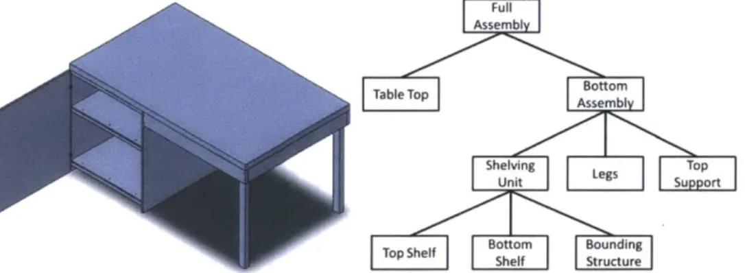
Figure 1: A visual representation of how the hierarchy for a given assembly may look. In this case, it is of a desk with a shelving unit. The most basic constituents, being the individual shelves as well as the box that contains both, are on the bottom tier in parallel. Next, the shelving unit assembly that contains the three aforementioned parts is in parallel with the legs and top support on a second tier, which are all part of the Bottom Assembly. Finally, this Bottom Assembly is in parallel with the table top and are what ultimately make up the full assem b ly ... 8 Figure 2: Image of typical output using generative templates and an input. The grey model in the front middle is the input and all other models are models derived from the features of the input with differences in scale and number of features ... 10 Figure 3: A snapshot from the CAD software model of Gaitan, a simple, two-tier table
com posed of plywood, balsa wood, and screws... 11 Figure 4: Image of part P.1 125T35.Gaitan.BottomShelf.CH, which is a "cut" and "hole" version
of P.1 125T35. This part is Gatain's larger top piece and has been modeled by editing the original raw material piece P. 1125T35, a 36" x 48" sheet of plywood from McMaster-Carr. The name and dimensions of each piece are stored in an Excel spreadsheet which keeps track of every part of every model used in the database. ... 12 Figure 5: Gaitan hierarchy showing the different tiers that allow for composability as discussed
in Section 2.1. The top-level tier is the assembly as a whole with four subordinates. Three of the four subordinates are simply pieces such as "Small Top", "Central Brace", and "Connectors", but "Bottom Assembly" has three subordinates of its own. This is the exact structure we were looking to have in these models as it allows for any one subordinate to be replaced by another, whether it be an individual part or an entire subassembly... 13 Figure 6: An image of Louise, a database model that has functionality in the way of hinges on
doors. In order to create the functionality assembly, a set of coordinates must be mated to the object that will be moving, in this case the door that will rotate via the hinge. This subassembly is then mated with the larger assembly in order to create the model. It is important that the coordinate system of the functionality subassembly matches the coordinate system orientation of the final assembly, as this allows the software to know how the two objects move with relation to each other on a particular axis. ... 14 Figure 7: Image depicting how the software creates a bounding box around every component in
a model to approximate parts and be able to create relations between them like co-linearity, concentricity, and co-planarity ... 15
Figure 8: Images of the connectivity software (left) that allows us to input the connections between pieces and what the interpreted connectivity graph looks like for Gaitan, the table seen in Figure 3. The image of the software pertains specifically to one of the legs, which can be seen is connected to four connectors and nothing else. The connectors then attach the legs to the large top, which is attached to the central brace via four more connectors, and finally the central brace is also attached to small top via more connectors as can be seen in the figure.
15
Figure 9: Image of input model (left) and completed model Sarah (right)... 16 Figure 10: Image of input model (left) and completed model Leah (right)... 16 Figure 11: Image of input model (left) completed model Danielle (right)... 17
1. Introduction
Fully customized objects are becoming commonplace in our daily lives. Whether it is jewelry, toys, furniture, or simple machines, there is growing interest in allowing casual users to design and then fabricate their own objects. We have seen this to, be true with the recent growth of 3D printers. What started as a concept for designers to dream about is now starting to become a common item that allows for complete control over the design and manufacturing of their creations. While 3D printers are great for many applications, they are limited in terms of materials, dimensions, and cost
Our goal is to allow customized design and assembly of man-made objects using common materials (e.g. wood, acrylic, screws, bolts, etc.) that most users have access to and can purchase easily. In order to do this, we are looking to create a system that will allow for a 3D model designed by the user to be used as an input from which a list of parts and connectors necessary for assembly can be generated. Although a user may know what object he or she wants, they may not know how to cut every piece, know where every connector should go, or know how two pieces should fit together.
Previous work [Lau et al. 2011] has approached this problem by using a grammar. The grammar, or set of rules, is applied to a software model to segment it into parts and connectors with which the user can then use to assemble his or her object. While this method works for a small number of models, it does not scale well because it needs many rules to compensate for complexity, as each rule is discrete to every category (e.g. cabinets or tables). We have chosen an alternative approach, one that consists of machine learning. Our system uses a database that supports software in order to extrapolate data from models and ultimately "learn" the rules of constructing models. Each of these models in the database contains information such as dimensions, alterations, limitations, and direct links to where each piece can be purchased. The user creates a model for input, the software compares the input to models in a database, and is then able to extrapolate what parts and connectors from online catalogs are necessary to
assemble the original input. This thesis is focused on the design and creation of such a database. Designing a database that is varied enough to accommodate almost any user input, yet be small enough to force the software to extrapolate the rules without being trivial is a delicate balance. Knowing that furniture will be the focus of our project, there are five major issues that need to be addressed: Composability (2.1), Functionality and Articulation (2.2), Structure Preserving Manipulation (2.3), Connectivity (2.4), and Manufacturing (2.5).
We have chosen to focus on furniture as the category spans a large and practical workspace for a project such as this one. Most furniture is relatively simple and easy to construct, so the concept can be proved quickly. Furthermore, furniture is highly practical, easily customizable, scaleable, and has a vertical assembly process. Our database also contains other man-made objects such as doll houses, jungle gyms, and go-karts, but those areas are yet to be completed. These will be further developed in coming semesters through MIT's Undergraduate Research Opportunity Program which allows undergraduates to conduct meaningful research in conjunction with PhD students and post-docs.
The structure of this thesis is as follows. Chapter 2 gives a brief and broad overview of the main challenges faced during the project. This chapter is meant to simply give an idea of what these issues are from a top-tier perspective. Chapter 3 goes into the details of what these five
issues actually are and how they were resolved by using an example of creating a model for the database. Chapter 4 is a conclusion in which the results of the project are discussed as well as the future work that will be required to further improve our system.
2. Overview and Main Challenges
The following sections will discuss the main challenges that needed to be overcome in order to have a successful project. These include composability, functionality and articulation, structure preserving manipulation, connectivity, and manufacturability of each model.
2.1 Composability
The first main challenge of this project is to create a database and software that allow for composability. In other words, the software and database need to allow the user to create completely new objects using any number of combinations of pre-existing parts. Our goal is to decompose models in the database that we know can be manufactured and be able to manipulate them in various scales. For example, suppose a user would like a desk that had storage shelves. They would use the interface to add a table top, four legs, and the shelves to the workspace. This could seem trivial but there are many possibilities for how this could be done. They could want two equally sized shelves, or they could want a small top shelving area and a larger bottom area, or they could want three shelves instead of two. These choices can quickly multiply until the user has an almost infinite degree of variation because there are micro-level refinement possibilities.
In order to create this kind of composability for the input models, we need to create a segmentation technique that will allow for each model in the database to be broken down to its individual constituents. This segmentation comes in the form of a hierarchy we have developed that clearly denotes the level of every single component within a model in the database.
The hierarchy breaks down as seen in Figure 1, which depicts an example hierarchy of a desk with a shelving unit.
Full
Assembly
Table Top Bto
Shelving Leg Top
Unit
Bottom Bounding
Top Shelf Shelf Structure
Figure 1: A visual representation of how the hierarchy for a given assembly may look. In this case, it is of a desk with a shelving unit. The most basic constituents, being the individual shelves as well as the box that contains both, are on the bottom tier in parallel. Next, the shelving unit assembly that contains the three aforementioned parts is in parallel with the legs and top support on a second tier, which are all part of the Bottom Assembly. Finally, this Bottom Assembly is in parallel with the table top and are what ultimately make up the full assembly.
The hierarchy is a vertical one with the smallest constituents, those making up the smallest components of the assembly, being at the bottom and the complete assembly being at the top. The software can take this grouping information and know how to replace certain pieces depending on the user's input. As mentioned in the example above, if the user wants three shelves instead of two, the software can simply add a middle shelf in the same tier of the hierarchy as the other two shelves. This allows the user to be able to have composability at different levels and helps expand the database.
2.2 Functionality and Articulation
On top of creating stationary objects like desks and chairs, users may also want to create objects that have a function like a chair with wheels or a hinged door or a sliding drawer. To be able to do this, the user must have a way to specify the desired functionality. We can create this freedom of being able to design dynamic objects by implementing a very simple naming scheme. This scheme, explained in more detail in Section 3.2.1, allows parts to have two degrees of
freedom: rotation and translation.
2.3 Structure Preserving Manipulation
Beyond the user being able to create new objects from different parts, they can also scale their objects to whatever size they want. They could want a taller table or a desk that is wider. Obviously, the input mesh cannot be scaled uniformly because the result would be a table with a tremendously thick top or a desk that has incredibly wide legs. To solve this issue, we base
scaling off of templates that can be resized independently of one another.
We need a way to scale different components at different rates but maintain the structural integrity of the original assembly, otherwise, scaling could result in objects that are not stable. In order to manipulate components while preserving the structure, we can use the fact that the models are already broken down into constituents and can therefore apply restrictions to scale
each component individually.
2.4 Connectivity
After the user has designed an object with whatever configuration and scale they desire, the software needs to be able to put all the pieces back together in the correct manner. The software will be able to "learn" from the models in the database how pieces connect together and will therefore be able to do this in real time as the user is designing an object.
This machine learning is made possible by having information of how components connect in order to make up the model. The information is provided to the software via a connectivity graph, which will be explained in more detail in Section 3.3.
2.5 Manufacturing
Finally, instructions that will allow the user to assemble a functional and structurally stable object must be created. Creating these instructions requires a list of parts and connectors that can be easily accessed by most people and that can completed using minimal tools or tools that are easy to acquire and most people probably own. For this reason, every single part and connector in every database model is linked directly to an online catalog where they can be purchased. We have linked all parts and connectors to products that can be found at Home Depot as well as McMaster-Carr. This is a major constraint as far as creativity because it restricts material choices to wood, glue, screws, and bolts while also restricting manufacturing processes to cutting and
drilling. However, we felt that these restrictions were justified because we want the system to be accessible to beginners and those that may not have a lot of experience designing and fabricating objects.
2.6 Approach
Because of the challenges described in Chapter 2, we decided to create a database of parts (generally pieces cut from raw material) and connectors (e.g. screws, bolts, hinges, etc.) that has each individually linked to an online catalog.
Using these parts, we created CAD models of man-made structures such as tables, chairs, doll houses, jungle gyms, and go-karts. Each of these CAD models carried crucial information about the particular model's construction and functionality.
First, these CAD models were all designed with a very specific hierarchy that allows for composability when the user goes on to design their own piece as described in Section 2.1. Then, each model that has any functionality, whether it be a wheel or a door or a drawer, has these functionalities notated in a special subassembly that tells the software of its capabilities. Finally, after the CAD models were completed, a connectivity graph had to be completed for each one. These connectivity graphs were crucial as they are what allow the software to "learn" from the database. We, as designers, had to ensure that the program understood how any two pieces in a CAD model assembly were put together and interacted. The connectivity graph was a way to ensure that the program was interpreting the models correctly and that it would indeed "know" that a screw holds two pieces of material differently than glue does, for example.
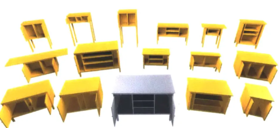
Using the information from the CAD models, a set of "generative" templates was then able to be created, allowing for new models to be derived using inputs as seen in Figure 2.
Figure 2: Image of typical output using generative templates and an input. The grey model in the front middle is the input and all other models are models derived from the features of the input with differences in scale and number of features.
3. Design
This section will walk the user through the process of designing a database model from start to finish. Particularly, we will walk through the design of a table named Gaitan. During this example, we will explain what composability, hierarchy, functionality, connectivity, and manufacturability are exactly, how they affect each model, and how they apply to designing models.
3.1 Creating Parts and Connectors
Each model in the database is designed using SolidWorks, a CAD software. The approach is much the same as it would be if these models were physical entities to be built by hand. This means that every model begins by CAD-ing the raw materials, all of which come from online catalogs such as McMaster-Carr or Home Depot, and then modifying them through cuts and holes to achieve the desired size and shape of each part.
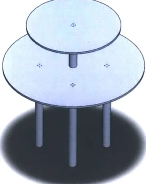
Gaitan, as seen in Figure 3, is a simple shelving unit consisting of plywood sheets, balsa wood boards, hinges, and connectors in the form of screws. To begin, we must first create the raw material models using the CAD software. For example, the larger top of Gaitan is a 36" diameter piece of plywood, but it was cut out of a 36" x 48" piece, McMaster-Carr #1 125T35. The original piece is modeled and saved as P.1 125T35 into the repository. Apart from having the SolidWorks file in the repository, a separate STL file that stores the corresponding 3D mesh must also be saved in order for the Design by Example software to be able to understand the mesh generated later. Also, the exact dimensions, part numbers, direct links to the online catalog where the parts can be ordered, and any special notes of each piece are logged into an Excel spreadsheet. This helps keep track of every part as well as setting limits for the software as to the size of each part. Furthermore, tracking special notes on dimensions allows us to limit when a piece can be cut in a certain direction or when a new piece is needed. For example, a stock piece can be cut to a smaller dimension in the X and Y directions, but the thickness, or Z direction cannot be modified, otherwise a new stock piece must be used.
Figure 3: A snapshot from the CAD software model of Gaitan, a simple, two-tier table composed of plywood, balsa wood, and screws.
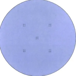
Once all of the raw materials have been modeled, we then edit them to meet the desired specifications. For the piece mentioned before, we manipulate the CAD model of the original raw material by cutting it to a 36" diameter and creating 16 holes for screws. Part P.1 125T35.Gaitan.BottomShelf.CH can be seen in Figure 4.
Figure 4: Image of part P.1 125T35.Gaitan.BottomShelf.CH, which is a "cut" and "hole" version of P.1 125T35. This part is Gatain's larger top piece and has been modeled by editing the original raw material piece P.11 25T35, a 36" x 48" sheet of plywood from McMaster-Carr. The name and dimensions of each piece are stored in an Excel spreadsheet which keeps track of every part of every model used in the database.
Connectors like screws, bolts, and hinges are a bit more straightforward as McMaster-Carr has CAD models of these pieces already. Each must be downloaded from the McMaster-Carr website and follow the same procedure of being saved as a SolidWorks part, an STL file, and notating its dimensions. Connectors that are more abstract (e.g. glue) or that do not have an associated 3D model (e.g. the ones from Home Depot) must be designed individually.
The naming scheme that we have chosen for parts and connectors is straightforward. As was mentioned before, the larger top of Gaitan is P.1125T35.Gaitan.BottomShelf.CH. The "P" represents that it is a part, the number matches the McMaster-Carr part number, "Gaitan" symbolizes that is part of the Gaitan model, "BottomShelf' is a description of the specific part, and finally "CH" means that the original part has been cut and had holes drilled in order to match the necessary dimensions and features. Connectors follow the same naming scheme except for the fact that they all begin with "C", which stands for "connector".
3.2 Creating Assemblies
After having all of the parts and connectors necessary to compose the model, we must then create assemblies. The idea behind these assemblies is to group the components that make up the whole in an organized and sensical manner. We have opted to create a hierarchal structure that allows for composability as mentioned in Section 2.1.
The idea behind the hierarchy is to group pieces of the model that should be together. This allows for the software to break down each model into its constituents and swap out sub-assemblies with different ones, creating composability. The idea is akin to any complex system. Take a car, for example. As a whole, it is a car but in more detail, the car is composed of many, many subassemblies. Each of these sub-assemblies in a model is modular and can be swapped
out just like the wheels or tires on a car.
More specifically, in the case of Gaitan, there are multi-step assemblies due to the fact that not every part is on the same tier. Figure 5 shows the hierarchy for Gaitan.
Gaitan Assembly
Bottom SalTp Central on
IAssemblySal o Brace nets
La rge <Top Legs (x4) Connectors
Figure 5: Gaitan hierarchy showing the different tiers that allow for composability as discussed in Section 2.1. The top-level tier is the assembly as a whole with four subordinates. Three of the four subordinates are simply pieces such as "Small Top", "Central Brace", and "Connectors", but "Bottom Assembly" has three subordinates of its own. This is the exact structure we were looking to have in these models as it allows for any one subordinate to be replaced by another, whether it be an individual part or an entire subassembly.
3.2.1 Specifying Functionality
Furthermore, more advanced assemblies can be made to create functionality like rotation for the hinges or wheels. Functionality subassemblies are simple but a bit different than the others. The role of each functionality subassembly is to allow the program to interpret how pieces move in relation to each other. Because Gaitan does not have any functionality, we will use another database model, Louise, as an illustrative example as to how functionality subassemblies are made.
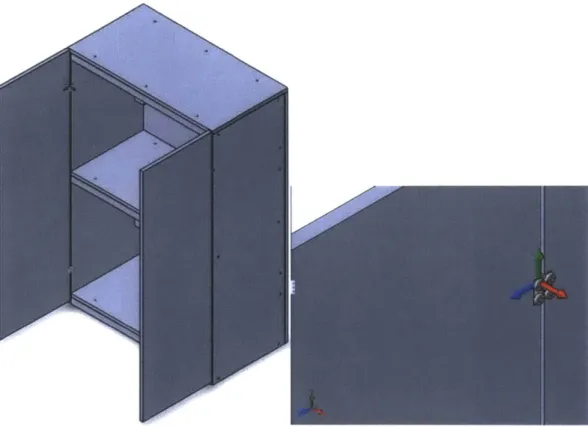
To create a functionality subassembly, a coordinate system is mated to the part, not the connector, that will end up moving. In the case of Louise, two functionality subassemblies would be created, one for each door. These would be named FUNCROT_X_0_90 for the left and FUNCROT_X_90_0 for the right, signifying that the functionality is a rotation of 90 degrees around the X axis of the assembly. The coordinates of the functionality assemblies and the overall assembly must match in order for the software to correctly interpret the functionality, so it is crucial to ensure that this is true. This is shown in Figure 6.
Figure 6: An image of Louise, a database model that has functionality in the way of hinges on doors. In order to create the functionality assembly, a set of coordinates must be mated to the object that will be moving, in this case the door that will rotate via the hinge. This subassembly is then mated with the larger assembly in order to create the model. It is important that the coordinate system of the functionality subassembly matches the coordinate system orientation of the final assembly, as this allows the software to know how the two objects move with relation to each other on a particular axis.
It is imperative to create the functionality subassemblies with the correct hierarchy because they need to be interchangeable, just like any other subassembly. Also, they need to be properly segmented in case there are two or more degrees of freedom. For example, if Louise was on wheels (e.g. the type found on office chairs), then the wheels would need to rotate around a central pivot to allow maneuverability in every direction as well as rotate down the central, horizontal axis to allow for movement forward and backward. Each of these functions is not mutually exclusive, much like the elbow and shoulder joints of an arm.
3.3 Connectivity
Once all of the components have been properly mated in SolidWorks, we have a digital model of Gaitan. However, this is not enough information for the model to be a useful database component as there is no information regarding the interactions and limits between two parts that the software can interpret. To remedy this issue, we have developed connectivity software that creates a connectivity chart.
This software takes full software models from 3DXML format and interprets the position of every piece in the model using the STL files mentioned in Section 3.1. Specifically, it creates a
bounding box around each component that allows it to create relationships between the boxes. These bounding boxes are simply rectangular prisms that approximate every piece as seen in Figure 7, allowing the software to create relations between parts such as co-linearity, concentricity, and co-planarity.
Figure 7: Image depicting how the software creates a bounding box around every component in a model to approximate parts and be able to create relations between them like co-linearity, concentricity, and co-planarity.
Once a 3DXML file is opened using the connectivity software, the software generates a guess as to which part interacts with which by finding intersections of the bounding boxes. By default, the program's first guess has parts only interacting with connectors, which should be the case in every assembly as the only function of connectors like screws, bolts, and glue is to hold two parts together. Often times, we simply have to verify that the software's guess is correct and that every part and connector is accounted for.
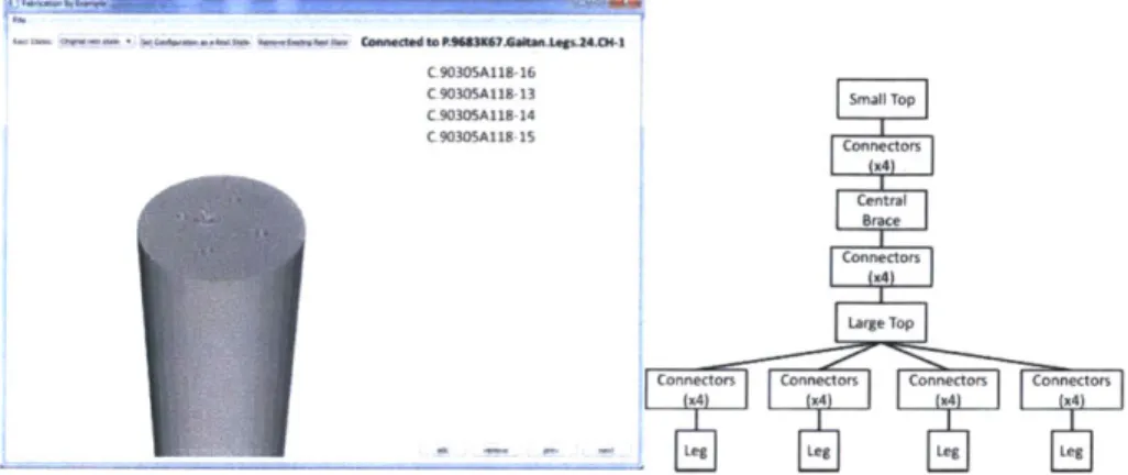
We have developed a simple interface for annotations that allows us to add additional information with more freedom outside Solidworks. Using this interface shown in Figure 8, we can manually specify the connectivity graph in the model, which the software then stores in a separate text file as a list of edges and intersections.
C90305A118-16 C90305A118-13 C .9030SAIIS-14 C 9030SAIBS IS Brace Connectors
Connector connecors Connectors Connecors M Leg [4 L g e Leg 4 Le
Figure 8: Images of the connectivity software (left) that allows us to input the connections between pieces and what the interpreted connectivity graph looks like
for Gaitan, the table seen in Figure 3. The image of the software pertains specifically to one of the legs, which can be seen is connected to four connectors and nothing else. The connectors then attach the legs to the large top, which is attached to the central brace via four more connectors, and finally the central brace is also attached to small top via more connectors as can be seen in the figure.
With this text file, this model has all of the required information to become a searchable and composable model for the database. Gaitan can now be scaled, broken down into constituents, or be used as is to find a match for a user input model.
4. Conclusion
This project has proved that the machine learning approach to customizability of design and assembly of man-made objects is useful, pragmatic, and versatile. After creating 43 different furniture models for the database, we were able to successfully construct two tables and a shelving unit using a 3D model input. The software was able to identify all of the necessary pieces and give a list of parts and connectors with dimensions for each. The software was not able to give assembly instructions but these models were simple enough such that being able to see the 3D object was enough to understand where every piece was supposed to go. Figures 9-11 show the finished models.
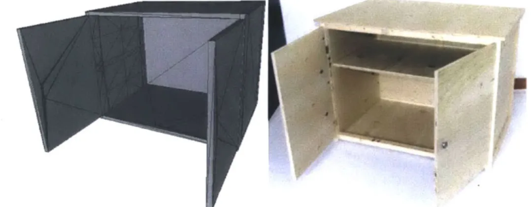
Figure 9: Image of input model (left) and completed model Sarah (right).
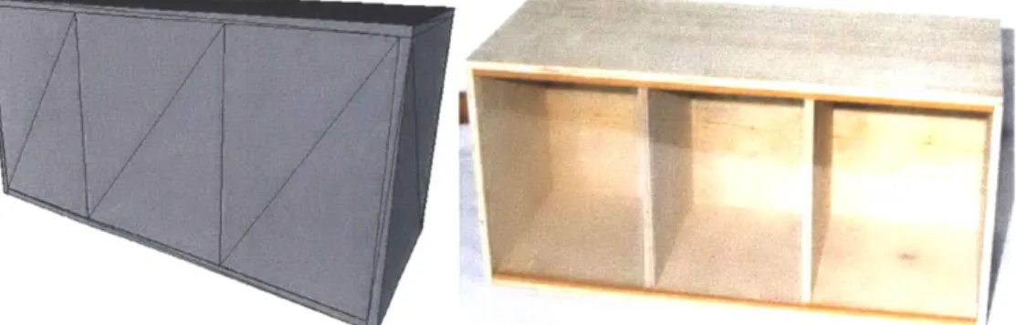
Figure 11: Image of input model (left) completed model Danielle (right).
4.1 Future Work
The future of this project lies on two fronts. The first is to further the scope and explore new categories. Beside the furniture models, the database currently has doll houses, jungle gyms, and go-karts. Although these categories have not been completed, they will be further developed in the future through MIT's Undergraduate Research Opportunity Program. The go-karts present a particularly difficult challenge because of the sheer complexity of such a machine. These will be electronically driven but composed completely of wood attached with screws, bolts, and glue because of the restriction that these models should be able to be fabricated by casual users, which means that we cannot assume everyone has access to a welder.
Secondly, the design process and the software need to be optimized. For example, we encountered some issues with wood splitting due to flaws in the database model design that could have been easily avoided with a few simple design changes. Furthermore, the early models in the database may not be the most optimized models in terms of using the smallest possible pieces because there was a focus on reusing the same raw material pieces in order to foster machine learning. While the software knows what the largest possible dimensions for a specific piece can be due to the information in the Excel spreadsheet discussed in Section 3.1, it does not currently have the capability of deciding when a new part number would be appropriate after cutting. For example, if a piece calls for a 2.5" x 3" x 1" plank and the database model is made with a 24" x 24" x 1" piece of raw material, the software cannot tell the user that buying the 4" x 4" x 1" plank of raw material would be a more appropriate choice and less wasteful. Another feature we would like to add is to have the software optimize the pieces that can be cut out of a single piece of raw material. Knowing that two 30" x 30" x 0.75" pieces can be had from a single 60" x 30" x 0.75" plywood sheet was something we had to account for ourselves when buying materials. The current software would have called for two sheets, creating much waste and overspending. Being able to have the software minimize the amount of materials bought will reduce waste as well as cost for each model.
Ultimately, our goal is to be able to release this system and share it with people. It would be a true test of its capabilities if hundreds or thousands of people were to be able to use it.
References
Lau, M., Ohgawara, A., Mitani, J., Igarashi, T. 2011. Converting 3D Furniture Models to Fabricatable Parts and Connectors. A CM Trans. Graph. 30, 4, Article 85 (July 2011), 6 pages. DOI = 10.1145/1964921.1964980 http://doi.acm.org/10.1145/1964921.1964980.