Design and Development of a Modular Test Machine for Students in
2.001
by Zoe Bornhorst MASSACHUSETTS INSTITUTE OF TECHNOLOGYJUL 16 2019
LIBRARIES
ARCHIVES
Submitted to theDepartment of Mechanical Engineering
in Partial Fulfillment of the Requirements for the Degree of Bachelor of Science in Mechanical Engineering
at the
Massachusetts Institute of Technology June 2019
Signature of A
0 2019 Massachusetts Institute of Technology. All rights reserved.
thor:
Signature redacted
Department o i enic ngineerin
May10 19
Signature redacted
Certified by: Accepted by: Martin Culpepper 0o f Mechanical EngineeringSignature
redacted
Thesis SupervisorMaria Yang-Associate Professor of Mechanical Engineering
77 Massachusetts Avenue
Cambridge, MA 02139 http://Iibraries.mit.edu/ask
DISCLAIMER NOTICE
Due to the condition of the original material, there are unavoidable flaws in this reproduction. We have made every effort possible to provide you with the best copy available.
Thank you.
The images contained in this document are of the best quality available.
Design and Development of a Modular Test Machine for Students in
2.001
by
Zoe Bornhorst
Submitted to the Department of Mechanical Engineering on May 10, 2019, in Partial Fulfillment of the
Requirements for the Degree of
Bachelor of Science in Mechanical Engineering
Abstract
The Mechanical Engineering course, Mechanics and Materials I (2.001), focuses on providing an introduction to the mechanics of solids with applications to science and engineering. While the current curriculum teaches in-depth theory, it can be improved in applicable knowledge. The focus of this thesis is the design, development, and evaluation of a modular test machine for students to build throughout the course. The design and build challenge will force students to explore the inner-workings of loaded structures and material properties. The pursued design emphasizes learning potential, gaining a physical feel of the course material, and ease of construction. This addition will walk students through the process of building a two-part lever design with a significant mechanical advantage and then acquiring material data from the structure they have built.
The design successfully measures the yield strength of a low-density polyethylene sample within its documented range. Initial testing of the structure with a group of previous 2.001 students resulted in an increased understanding of loading, material properties, and mechanical advantage, when compared to previous testing prior to structure introduction. Estimated outcomes of this new model display increased efficiency among students, saving them an average 4 months of delayed extracurricular activities, 30 hours of unnecessary work, and another 20 hours of poor designing.
Thesis Supervisor: Martin Culpepper Title: Professor of Mechanical Engineering
Acknowledgements
I would like to thank Martin Culpepper for the opportunity to work on this project as well as
design advice and writing help along the way.
I would like to thank Pierce Hayward for the material advice and testing equipment knowledge.
I would like to thank students Amanda Garofalo, Eddy Garcia-Montes, and Mitch Maisel for
Contents
Abstract Acknowledgements List of Figures Introduction 1.1 Overview of 2.001 Design Concepts2.1 Customer and Functional Requirements 2.2 Concept Generation
2.3 Concept Comparison Design Evolution
3.1 Ensuring Feasibility of Design 3.2 Expanding Design
3.3 Model 1 3.4 Model 2 3.5 Model 3 3.6 Model 4
Evaluation of Final Design 4.1 Setup
4.2 Data Acquisition with Device 4.3 Student Testing
Conclusions and Future Work
3 5
9
11
13 17 18 20 22 25 25 28 31 32 33 47 51 51 52 57 61List of Figures
Figure 1-1: (a) final CAD design, (b) final machined structure, (c) loaded structure acquiring
data of an LDPE sample 12
Figure 2-1: Desktop Instron design 20
Figure 2-2: Proposed lever design 21
Figure 2-3: Inspired nut cracker designs 22
Figure 3-1: Setup I lever 29
Figure 3-2: Setup 2 lever 29
Figure 3-3: Setup 1 and 2 embedded to produce a multiplied mechanical advantage 29
Figure 3-4: The first version of the two part lever design 31
Figure 3-5: The second iteration of the lever design 32
Figure 3-6: Dogbone punch to create material samples 33
Figure 3-7: Sample attachment 34
Figure 3-8: FBD of the right lever arm 35
Figure 3-9: Dimensions of right lever arm 36
Figure 3-10: FBD of the left lever arm 37
Figure 3-11: Dimensions of the left lever arm 37
Figure 3-12: Different dogbone dimensions. (a) is for 1.6 mm low-density polyethylene and
(b) is for 0.76 mm polycarbonate. 43
Figure 3-13: 2.224 N weight for loading structure 44
Figure 3-14: CAD design of the basket 45
Figure 3-16: The machined Model 3 design 46 Figure 3-17: Final design dimensions, showing increased post height and basket height 47 Figure 3-18: Dimensions of the new right lever arm with added modularity 48
Figure 3-19: CAD model of the final lever design 49
Figure 3-20: Machined final lever design 50
Figure 4-1: LDPE dogbone sample dimensions 51
Figure 4-2: Close up of sample clamped on top and bottom 52
Figure 4-3: Acquiring data with 2.224 N loaded on the weight basket 53
Figure 4-4: Acquiring data with 8.896 N loaded on the weight basket 54 Figure 4-5: Force vs. Displacement plot from test with LDPE sample 55 Figure 4-6: Stress vs. Strain plot from test with LDPE sample 56
Chapter 1
Introduction
The focus of this thesis is the design, development, and evaluation of a student-built modular test machine for the 2.001 course, Mechanics and Materials I. The course focuses on providing an introduction to the mechanics of solids with applications to science and engineering. The current curriculum can be improved in applicable learning. This additional project operates under the MIT motto of Mans et Manus ("Mind and Hand") to enhance the student experience through developing real-world, problem solving engineering foundation.
With this addition to the 2.001 course, students will explore the inner-workings of loaded structures and material properties without an excessive cost of building the device. This will minimize professors' use of resources while creating a platform for them to be more effective in their class. In turn, the MIT Department of Mechanical Engineering will graduate more qualified and capable engineers. After surveying multiple undergraduate Mechanical Engineers, students emphasize that with a more in depth grasp of the 2.001 material, they would have participated in maker spaces and other extracurricular building opportunities.
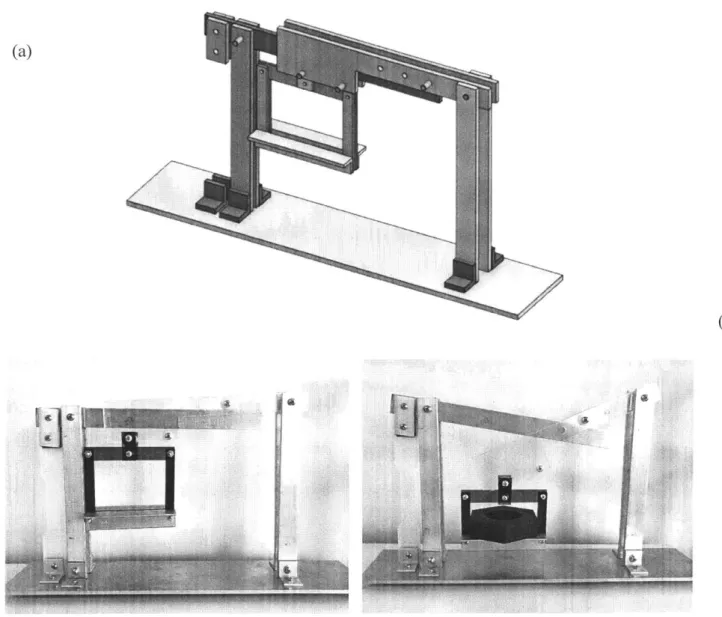
This project will walk students through major 2.001 concepts by having them design and build a two part lever system with a significant mechanical advantage and then acquire material data from the system they have built. Figure 1-1 .a shows the CAD of the final design, Figure 1-1 .b shows the final machined structure, and Figure 1-1 .c shows the structure loaded with a
low-density polyethylene (LDPE) sample, acquiring data. Initial testing of this structure showed excitement and an increased understanding of loading, material properties, and mechanical advantage.
(a)
(c)
6
Figure 1-. (a) final CAD design, (b) final machined structure, (c) loaded structure acquiring data of an LDPE sample
1,
1.1 Overview of 2.001
1.1.1 2.001 Course Content
2.001 is the introductory Mechanical Engineering course. Appendix A shows the syllabus and
schedule for 2.001 in Fall 2018. Students begin the semester learning about structures, stress and
strain. They then go into torsion and bending.
Currently, 2.001 does have a hands on component. Professor Ely Sachs introduced the Discovery
labs. Ely Sachs' guided discovery teaching method is described as "a way to enable students to
play a more active role in their learning. It allows students to essentially "discover" new material
as if they were the first ones to come to these conclusions, and is particularly useful when they
have not been exposed to it before." [2]
Sachs held an xTalk walking through the 2.001 class on shear strain, and an MIT junior who
attended commented:
"It is often easy for students to attend class and leave without a greater understanding of the material. I have admittedly often walked out of lectures myself not fully understanding what had occurred because I is not fully engaged the whole time. However, when students play an active role in their learning, it is much easier to both pay attention and retain the information that is taught. This can have great implications for students' learning, as more guided discovery in classrooms can enable students to truly understand the material and grasp fundamental concepts that they will use even after
leaving MIT." [2]
These Discovery labs are a great addition to get the students touching the materials, and as
mentioned, helps them retain the information that is taught. However, they do not force the
the Discovery labs to give the students experience building and force them to apply the 2.001 material with the hope of fully grasping the concepts.
1.1.2 Reason for Targeting 2.001
The decision to target the course 2.001 to add such a design component stemmed from its basis as the introductory Mechanical Engineering course. This course sets up the rest of the student's MIT career as a Mechanical Engineer. As mentioned in the Introduction, part of the implication of this thesis is to influence students to use their engineering knowledge outside of their
coursework as early as possible so they graduate as much stronger engineers.
Amanda Garofalo, a sophomore who took 2.001 in Fall 2018, commented, "I theoretically knew everything after 2.001 but I didn't have a great grasp because I never actually did it. It is a lot of theory, it would have been great to touch and build." She has since joined the driverless car team after taking 2.007, and mentioned she would have joined the team a lot earlier if she had been more confident in her understanding of 2.001 concepts.
1.1.3 Reason for Chosen Topics
Choosing to focus on loaded structures, beam bending, and material properties, is based off my personal experience at MIT. We cover an immense amount of content in 2.001 and I completed the course lacking a physical feeling for this material in particular. For example, when I interviewed for summer internships and built my robot in 2.007, I lacked the physical feel of
Based off my experience in 2.001 and students feedback, viscoelasticity is one of the most confusing topics. It is hard for the students to get a physical grasp of this material. Therefore, I have chosen to ensure this machine can test various viscoelastic materials.
Chapter 2
Design Concepts
The progression of the design of this structure must align with the weeks the student learns each topic. The student will learn about the following topics each week:
1) Axially loaded structures
2) Linear Elastic Axially loaded structures
3) Misfits, Thermal Strain, Plasticity
4) Truss structures
5) Rigid bodies with truss supports
6) [Quiz 1] 7) Time-dependent deformation 8) Torsion I 9) Torsion II 10) Bending I 11) Bending II 12) Bending III
13) Multi-axial stress and strain
14) Failure and stability 15) Course review
This order of topics is carefully considered throughout the design process to ensure the student will be able to learn the theory first, and then apply that knowledge to building.
2.1 Customer and Functional Requirements
The customer requirements are shown below in Table 2.1. The most important requirements for this design are its learning potential and giving the students a physical feel of what is happening. Next, the structure must be easy to construct as they need to build it in a semester, without too much additional time than their current 2.001 coursework. The device should be able to test a breadth of materials to give students a feel for how different materials behave. It should be easy to use and operate so they can test many materials quickly. Finally, a take home aspect involved will give students a souvenir after completing 2.001.
Table 2.1: Customer Requirements
Customer Requirements
Learning potential
Physical feel of what is happening Ease of construction
Breadth of testable materials Ease of use
The functional requirements are shown in Table 2.2. The purpose of this test machine is not in developing highly accurate stress/strain curves, but to physically understand what a stress/strain curve means. Therefore, it must be reasonably accurate and resolute, but not highly.
Repeatability is important so the student is able to test multiple material samples. An accuracy, resolution, and repeatability of 2.5% is enough to ensure the device is useful and meaningful for the students without requiring unnecessary complexity. It is important to keep the device as simple as possible for the student to grasp a feel for what is happening.
Table 2.2: Functional Requirements
Functional Requirements
Accuracy 2.5%
Resolution 2.5%
Repeatability 2.5%
2.2
Concept Generation
The initial concept was to create a desktop universal test machine. Initial research looked into DIY test machines that students would be able to build in a semester given a kit of materials. Figure 2-1 shows an example of a universal test machine that could be built by a student. Some initial concerns with this design were complexity and cost. Additionally, it seemed too literal an expansion from the Instron machines the students will use during their lab periods. The
additional learning that a student receives from building a smaller version of the Instron is limited.
rA
Figure 2-1: Desktop Instron design
This led into an exploration of simpler, more effective methods of displaying the textbook knowledge. Figure 2-2 shows a lever design with a significant mechanical advantage, in which the student attaches a sample on the left and loads the structure with weights on the right. As
more load is applied, the sample will eventually yield. The student can measure the displacement of the sample for each given load and produce a Force vs. Displacement plot. They can extract this data to create a Stress vs. Strain plot for the sample material.
Figure 2-2: Proposed lever design
After exploring the lever design, alternative designs in which the student could have a significant take home aspect were investigated. Nut crackers employ a similar technique to the lever design. Two nut cracker designs are shown in Figure 2-3.
Figure 2-3: Inspired nut cracker designs
2.3 Concept Comparison
To determine which design to move forward with, the desktop Instron design, lever design, and nut cracker design were compared using the Customer and Functional Requirements discussed in
Chapter 2.1. A Pugh chart is used as the method of comparison, shown in Table 2.3.
Table 2.3: Pugh chart comparing the desktop Instron design, lever design, and nut cracker design
Customer Requirements Desktop Instron design Lever design Nut cracker design
Learning potential 0 + +
Physical feel of what is 0 ++ +
happening
Ease of construction 0 ++ +
Breadth of testable materials 0
Ease of use 0
The Instron design would be rooted mostly in the testing of materials rather than the
understanding of loaded structures, stiffness, and beam bending. The nut cracker design has the most valuable take home aspect, but adds unnecessary complexity as compared with the lever design. Additionally, the lever design can also act as a nut cracker for a take home aspect. The decision to move forward with the lever design is driven by its simplicity and ability to give students the strongest physical feel for the chosen course material.
Take home aspect 0 + ++
Functional Requirements
Accuracy 0
Resolution 0
Chapter 3
Design Evolution
After committing to the lever design, calculations were run to ensure the feasibility of the design. The design was then fleshed out and expanded.
3.1 Ensuring Feasibility of Design
Preliminary calculations were made to determine if the loads required were reasonable. Next, the maximum deflection of the beam is compared to the AL of the sample to ensure the beam deflections are small compared to the AL of the sample.
As an example, taking an aluminum sample of cross-section 2.5 mm x 2.5 mm and
ay = 240 MPa, its yield force is calculated as follows:
Fy= A x ay (3.1)
A = 6.5
x
10-6 M2Assuming a ratio of 10:1 between the lever arm connecting from the pivot point to the weight and the lever arm from the pivot point to the sample, the load required to yield the sample is calculated: Fload = I MechanicalAdvantage 1560 N Fload = 10 = 156 N = 35 lbs 10
This result shows the load required would be 156 N (35 lbs), a reasonable amount.
The maximum deflection of the beam, 6max, can be calculated using equation:
WL'
6max = 3EI
(3.2)
(3.3)
where W is the load, L is the length of the beam, and E is the Young's Modulus of the material. I is the Moment of Inertia, and is calculated by:
bh3
I=1 (3.4)
The beam deflection is then compared to the AL of the sample when it yields. The yield strain cy of the sample is given by:
--Using the definition of strain, it is also equal to: AL
Y = (3.6)
Combining equations 3.5 and 3.6 gives the AL of the sample when it yields:
ALsampe =- x L
E
As mentioned, it must be ensured that ,max < < ALsample.
These initial calculations were expanded to populate a spreadsheet to easily change dimensions and observe its effect on the forces and deflections. Table 3.1 shows the AL and maximum deflection of the supporting beam based off the dimensions of an aluminum sample.
-A
Table 3.1: Spreadsheet showing initial calculations
SAMPLE SUPPORTING BEAM
Material Aluminum 6061 Steel
E [Pal 68900000000, 2E+ 11
Yield Stress [Pal 240000000
L Im] 0.15 0.5 b [ml 0.025 h [m] 0.076 A [m^21 0.0000065 W [N] 156 9. 14533E-07 delta L ImI 0.000522496
Max Deflection [ml 3.55373E-05
3.2 Expanding Design
Initial explorations focused on how this design could be used to test different beam stiffnesses, different beam cross sections, and torsion. Next, the lever design was optimized.
Inspired by the design of household scales, the lever design was expanded into two levers that come together to produce a mechanical advantage of 100:1 instead of simply 10:1. Figure 3-1 shows the first lever that would be built and Figure 3-2 shows the second lever that would be built. They are then embedded to produce the setup shown in Figure 3-3, in which the force, F2, from Setup 2 is applied on Setup 1. Fl is the force of the sample and F4 is the load.
F1 F
Figure 3-1: Setup ] lever
0 A F3 = F2
0
Figure 3-2: Setup 2 lever
Force from Setup 2 applied to Setup I
0
Load
0
-J
F4
Figure 3-3: Setup 1 and 2 embedded to produce a multiplied mechanical advantage
F2
I
Sample
While completing the CAD design, it became clear that for practical geometric reasons, the dimensions had to be decreased, which caused the mechanical advantage to decrease to 34:1.
The hypothetical process of the student going through the design of these setups could be as
follows:
1) Build Setup 1
2) Test with sample material and produce stress/strain curves
3) Calculate force relationships
4) Build Setup 2
5) Test with sample material and produce stress/strain curves
6) Calculate force relationships
7) Combine Setup 1 and Setup 2 and calculate new force relationship and mechanical
advantage
8) Test various material samples
After building the embedded lever design, the student could test many different types of
materials and produce stress/strain plots accordingly. The big advantage of the embedded design is the ability to reach much higher yield forces with less loading. Additionally, the higher
mechanical advantage causes a greater AL of the sample, which will make it easier to measure the displacement when collecting data.
3.3 Model
1
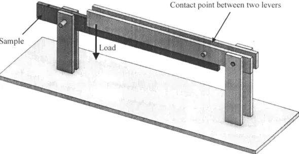
The first CAD model of the embedded lever is shown below in Figure 3-4. The sample attaches on the far left and weights hang from the ends of the right side beams, as denoted by "Load."
Contact point between two levers
Figure 3-4: The first version of the two part lever design
After laser cutting this first model, there was concern with stiffness in the right side beams. Additionally, a method of holding the weight needed to be designed.
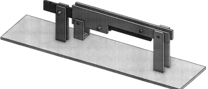
3.4 Model 2
Model 1 led into Model 2, in which the shape of the right side beams was modified to make the beams stiffer and easier to hang weights from. As seen in Figure 3-5, the right beams are attached to each other by two pins. The weights hang from the left most pin.
3.5 Model
3
After identifying issues with Model 2's performance, Model 3 was designed accordingly. The focus was on developing a robust design that would be able to test materials. Angled aluminum was added to secure the structure to the base, clamps were added to secure the sample, and an analysis was run to determine dimensions and materials.
3.5.1 Sample Shape
After speaking with Pierce Hayward about viscoelastic materials and rubber samples, it was determined that dogbone samples would be best to ensure failing occurs due to maximum tensile loading. Figure 3-6 shows a dogbone punch that could be used to create material samples.
3.5.2
Sample Attachment
The sample must be clamped to the beam to ensure proper yielding. The design of this clamp must be flexible to test different sample thicknesses. As seen in Figure 3-7, two aluminum pieces clamp onto the sample and also attach onto the outsides of the lever beam. The sample is also clamped to the bottom.
3.5.3 Determining Dimensions and Materials
An analysis was performed to determine the loads and displacement of the sample. Because of the high mechanical advantage of the device, the weight of the levers constitute a significant initial force on the sample. The force required to hold this fixture up is determined below.
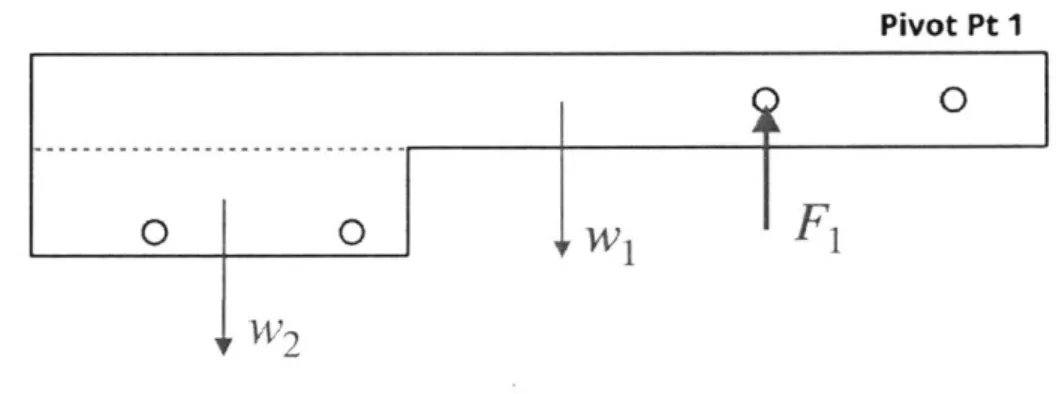
A Free Body Diagram (FBD) of the right lever arm is shown in Figure 3-8. The weight of the
beam has been split into w, and w2. The force F1 is at the contact point between the right and left
lever arms. Pivot Pt 1 0
4
0 1 0 W1I
F
1 w2Figure 3-8: FBD of the right lever arm
29.210 mm
101.600 mm
--
274.320 mm
215.900 mm
Pivo Pt II'0
0 025.400 mm
4
--
50.800 mm
Figure 3-9: Dimensions of right lever arm
The weight, w, is given in terms of density, p, volume, V, and gravity, g: w = p x V x g
This beam is made out of 0.0063 m thick acrylic, and because there are two right beams, w, and w2 are calculated using a thickness of 0.013 m to account for both beams. Given the dimensions in Figure 3-9, the weights of the beams are calculated:
Pacrylic = 1163 kg/m3
w, = 1163 kg/m3 x (0.013 m x 0.025 m x 0.274 m) x 9.81 m /s2 = 1 N
w2= 1163 kg/m3 x (0.013 m x 0.029 m x 0.102 m) x 9.81 m /s2 = 0.43 N
The sum of the moments about a Pivot Point is zero.
I Mpiypt = 0 (3.
36
Summing the moments about Pivot Point 1 in Figure 3-8 results in:
0.051F, = 0.11w, + 0.2w2
F1 = 3.84 N
A Free Body Diagram of the left lever arm is shown in Figure 3-10. The weight of the beam is
w3. The force F1was calculated above. F2is the force from the sample.
F
1Pivot Pt 2
Ii'
0
FJ
4rFigure 3-10: FBD of the left lever arm
The corresponding dimensions of the lever arm are shown in Figure 3-11.
304.800
mm
Pivot Pt 2
0? 0
254.000
mm
25.400
mm
Figure 3-11: Dimensions of the left lever arm
31.750 mm
This beam is aluminum with density, Paluminum , w3 is calculated:
Paluminum = 2700 kg/rm3 w3 = 1.33 N
The moments about Pivot Point 2 are summed and equated to zero:
I Mpitpt = 0
0.032F2 = 0.12w3 + 0.24FI
F2 = 33.8 N
In order to be reasonably accurate, when the sample is attached, it should not yield more than about 10% before the structure has been loaded with weights. This means, the sample should have a yield force greater than ~338 N. When determining the dimensions of the sample in Chapter 3.5.5, it will be required that the material's yield force is greater than 338 N.
3.5.2
Mechanical Advantage
The Mechanical Advantage is calculated below in Equation 3.9 by multiplying the ratios of the lever arms. It must be ensured that these dimensions are from the pivot points and not simply the lengths of the beams.
254 mm 215.9 mm
Mechanical Advantage = x = 34 (3.9) 31.75 mm 50.8 mm
3.5.3
Yield Force
Next, the force required for the sample to yield is calculated using Equation 3.10. A is the cross-sectional area of the sample and ay is the yield strength of the sample material.
Fy= A x cy (3.10)
For example, looking at High Strength Neoprene Rubber, which has a Uy = 8.96 MPa, and a
sample of cross-section: it t = 0.0063 m w = 0.01 m * A = (w)(t) = (0.01 m)(0.0063 m) = 6.3 x 10⁻⁵ m2 Fy = 565 N
Because of the mechanical advantage, the structure will be loaded with less weight:
Fload = (3.11) MechanicalAdvantage 565 N Fload 5 = 3.8 N 34 :4 I
3.5.4
Maximum AL of Sample
Next, the AL of the sample when it yields is calculated. The yield strain ey is: ay
ey
=-E
Using the definition of strain, it is also equal to:
AL
Combining equations 3.12 and 3.13, the AL of the sample when it yields is:
(3.12)
(3.13)
ALsample = x L
Due to the mechanical advantage, the corresponding displacement of the weight basket, 3basket'
is:
6basket = ALsample x MechanicalAdvantage (3.14)
Looking at the rubber sample from 3.5.3, which has an E = 1.0 MPa, and assuming the sample is of length L = 0.051 m, the AL of the rubber sample when it yields is:
8.96 MPa
ALsample = x 0.051 m = 0.46 m
1.0 MPa
6basket = 0.46 m X 34 = 15.6 m
This 8basket is unfeasible for realistic dimensions of the structure. Therefore, alternative, stiffer materials were explored.
3.5.5
Material Selection
As this rubber sample would be impractical to use, an examination of different materials was conducted.
For example, HDPE, a much stiffer material with oy = 28.27 MPa and E = 799.79 MPa:
A = (0.0063 m)(0.01 m) = 0.000063 m2
Fy = 1781 N 1781 N
Fload = 4 = 52.4 N
To achieve the yield force of 1781 N the structure would need to be loaded with Fload = 52.4 N. The AL of the HDPE sample when it yields, assuming the sample is again of length
L = 0.051 m:
28.27 MPa
ALsample = 799.79 MPa x 0.051 m = 0.0018 m
6
basket = 0.06 m
The abasket is very reasonable. Loading the structure with 52.4 N (12 lbs) is doable, however, 1781 N (410 lbs) will put a lot of stress on the aluminum beam and that side of the structure. In
order to decrease Fy, the thickness or width of the sample could be decreased.
A more formal analysis was conducted to compare various materials and dimensions with the
goal of finding a material with the desired Fload , AL , and 6basker
Table 3.2: Comparing Sample
Material Name Yield Strength Young's (Mpa) Modulus (MPg) Rubber 8.96 1.00 HDPE 28.27 799.79 HL)PE 28.27 799.79 PC 63.00 2068.43 PC 65.50 2275.27 PC Film 65.50 2275.27 PC Film 65.50 2275.27 LDPE Film 13.79 275.79 LDPE Sheet 13.79 275.79 LDPE Sheet 13.79 275.79 PTFE 15.17 496.42 Materials Thickness (10.)1 10.16 10.1 4.572 1.5875 0.762 0.762 1.016 0.1016 1.5875 1.5875 0.79375 and Dimensions Width Length (mm) (HIm) 6.35 6.35 6.35 6.35 6.35 12.7 6.35 25.4 6.35 19.05 25.4 50.8 25.4 25.4 25.4 25.4 38.1 25.4 25.4 25.4 60.96 25.4
Slight alterations in the dimensions of the sample will drastically change the Fload and 3
basket-3.5.6
Dogbone Samples
After running calculations and determining the desired sample dimensions, the current dogbone punch sizes were no longer usable. Therefore, customizable dogbone samples to be laser cut were designed. This way, the dimensions could quickly be changed and multiple different dogbones could be cut. The chosen materials had to be safe for a laser cutter.
Each material has different properties and lends itself to a different size sample. Therefore, several different dogbone sizes for the different materials were produced. Two examples of dogbone designs for the 1.6 mm low-density polyethylene and 0.76 mm polycarbonate are shown in Figure 3-12. F yield (N) 578.27 1823.77 820.70 635.05 316.94 633.87 422.58 35.59 139.01 417.02 305.82 F load (N) 17.01 53.64 24.14 18.68 9.32 18.64 12.43 1.05 4.09 12.27 8.99 Sample delta L (mm) 455.45 0.90 0.90 0.77 0.73 1.10 0.73 1.27 1.27 3.05 0.78 Basket displacement (mm) 15485.24 30.52 30.52 26.30 24.86 37.29 24.86 43.18 43.18 103.63 26.39 -1
(a) 0 0
(b) 0 0
Figure 3-12: Different dogbone dimensions. (a) is for 1.6 mm low-density polyethylene and (b) is for 0.76 mm polycarbonate.
3.5.7
Holding Weights
To load the structure, a basket for stacking weights was designed and built. The weights available
for use are hexagonal shaped 2.224 N (0.5 lb) weights as shown in Figure 3-13.
Figure 3-13: 2.224 N weight
for
loading structureThe basket was designed so the user could easily stack the weights. The basket design is shown in Figure 3-14. The base is made of two aluminum angle irons and the rest is laser cut out of 3.17 mm acrylic. The top hole attaches and hangs from the structure, as seen in Figure 3-15.
--.-Figure 3-14. CAD design of the basket
F ] T
Figure 3-15:- The basket hanging
from
the structure; %4l
.1
For Model 3, the basket was made fully out of laser cut acrylic. However, in the final Model 4 version, the aluminum angle irons were used. The machined Model 3 is shown in Figure 3-16.
3.6 Model 4
For the final version, modularity in the design was added so the user has the ability to change the mechanical advantage. Additionally, the post heights were increased for the final model to allow for a greater 3basket. The height of the basket was also increased to allow for stacking more
weight. The final dimensions are shown below in Figure 3-17.
0 0 0
0 0
I I
0
LI
Figure 3-17: Final design dimensions, showing increased post height and basket height
Adding Modularity
To add modularity and expand upon the testable materials, holes were added in the right lever arms so the user can adjust the mechanical advantage. This allows the student to have more
flexibility in their material samples and also gain a physical feel for different mechanical advantages.
274.320 mm
---
215.900 mm
J~~
I-t__
0 0 029.210
mm
Lk
-"
-101.600 mm
--Pivot Pt 131.750 mm
31.750 mm
50.800 mm
25.400
mm
A
Figure 3-18: Dimensions ofthe new right lever arm with added modularity
I
3.6.2 New Mechanical Advantage
With these added holes, the Mechanical Advantage ranges from 15 to 34, as calculated below:
Mechanical Advantage = Mechanical Advantage = Mechanical Advantage = 254 mm, 31.75 mm 254 mm 31.75 mm 254 mm 31.75 mm 215.9 mm
x
=3
50.8 mm 215.9 mm =21x
=2
82.55 mm 215.9 mm =15 x =m 114.3 mmFigure 3-19 shows the final CAD design will these additions, and Figure 3-20 shows the final machined design.
Chapter 4
Evaluation of Final Design
After building the final design, it was tested with various material samples to evaluate its
performance. Additionally, testing with students was conducted to evaluate its learning potential.
4.1 Setup
A test was run with a 1.59 mm thick LDPE sample. The sample and its dimensions are shown in
Figure 4-1.
length = 63.5 mm
4----+ width = 19.05 mm
Figure 4-1: LDPE dogbone sample dimensions r
_____________________________________________________ *1
The sample was clamped to the base and attached to the beam as shown in Figure 4-2.
Figure 4-2: Close up of sample clamped on top and bottom
4.2 Data Acquisition with Device
To acquire data, when the sample is first attached, the device is held up to prevent load on the
sample. This is data point (0,0). Next, the device is released so that the sample experiences the
weight of the beams. With this weight, the distance from the bottom of the basket to the base is
- -- - ---- 3MMML- -- --
-and the distance is measured accordingly. Figure 4-3 shows the structure when the first 2.224 N weight is added. Figure 4-4 shows the structure when four 2.224 N weights have been added.
Figure 4-3: Acquiring data with 2.224 N loaded on the weight basket
Figure 4-4: Acquiring data with 8.896 N loaded on the weight basket
4.2.1 Experimental Results
These data points were then plotted to produce a Force (N) vs. Displacement (mm) graph in Figure 4-5 and a Stress (MPa) vs. Strain (/) graph in Figure 4-6.
40 -30 -3 20 10 0 0 25 50 75 100 Displacement (mm)
30 r -22.5 15 7.5
0
0 0.02 0.04 0.06 0.08 Strain (/)Figure 4-6: Stress vs. Strain plot
from
test with LDPE sample4.2.2 Discussion of Results
As seen in Figure 4-5, the sample yields when the weight of the device is released. The shape of these curves correlate fairly accurately with typical Force vs. Displacement and Stress vs. Strain plots for LDPE. The yield tensile strength for LDPE typically ranges from 10.3 - 18.0 MPa [9].
An error in the data collection results from an error due to geometry with respect to the definition of mechanical advantage. The mechanical advantage is the horizontal distance between the weight basket's pivot point and the contact point between lever 1 and 2. When the structure is loaded with more weight and the lever arms have dropped significantly, as seen in Figure 4-4 above, this error is most prevalent.
4.3 Student Testing
The design was tested with Amanda Garofalo, a current sophomore who completed 2.001 in Fall
2018, Eddy Garcia-Montes, a current senior who completed 2.001 in Fall 2016, and Mitch
Maisel, a current senior who completed 2.001 in Fall 2016. The intention was to test the machined model with these students and gauge their added physical understanding of the material. Following the test, they were all very excited about the structure and watching the material yield. Their understanding of the physics and mechanical advantage was gauged by their ability to apply this knowledge when asked several questions.
Following the test with Amanda, she mentioned, "I love adding the weights and actually
physically seeing the difference. Super cool." She also noted really liking the ability to move the contact point and change the mechanical advantage. After taking 2.007, Amanda joined the driverless car team. She mentioned she would have joined the team a semester sooner if she had been confident in her 2.001 concepts. The confidence she was missing from not having grasped the concepts delayed her four months of applying this knowledge into extracurricular
engineering opportunities. As for feedback, Amanda suggested adding ruler markings on the left post to easily read the displacement of the basket. This suggestion should be employed in future iterations of the design.
After testing the device with Eddy, Eddy commented, "This would have saved me a month of trial and error on my robot in 2.007." Further questioning asked Eddy about the types of errors he could have avoided with this new knowledge. He shared that he spent an estimated 30 hours building a robot that wasn't stiff enough and he had to scrap it and start over. He said that now he wouldn't have wasted those 30 hours, because he would have designed the robot correctly the first time. I pried further as to what he would have changed now. He said he was trying to determine the best structure for each individual scissor in his scissor lift. He added, "I did this L shape with aluminum, but it was kind of arbitrary and I wish I would've known a better material and geometric structure that I could've used to efficiently make a functional scissor lift." I asked him what material and structure he would use now. He responded, "Might've stayed with
aluminum because it's light, but I just felt that I may have made my scissors longer than they needed to be in general. They were plenty stiff, but maybe adding the extra aluminum to
optimize my shape/stiffness made it too heavy. It took a lot of force for my winch to get it up. So any friction caused it to fail. If I could've made it lighter without compromising stiffness I would've benefitted."
Because Eddy only tested plastic dogbones with this testing device, when questioned about specifics of material and structure he was unable to apply it to his robot. He knew there were better material and structure choices out there, but was unclear what they were. Although the
current state of the design is unable to test beam stiffnesses, one could use this design to test many different materials and structure stiffnesses, which will be discussed in Chapter 5.
After Mitch tested the device, he was asked to tell a story of a time where this new knowledge would have made a significant impact on his educational experience. He discussed his
experience at a UROP. Mitch said he understood everything in 2.001 but didn't get to touch anything so he didn't gain the physical understanding. He wished he had learned it in class instead of wasting time in his UROP. He estimated he wasted 20 hours with poor designs that could have been avoided if he had understood 2.001.When asking Mitch about the time he would save, he responded with, "But more importantly than saving time, this increases my
understanding to make or produce a better end product. It allows me to make better, more effective projects." He added, "You are going to learn it eventually, but you have to do it to understand it. This design challenge is great because it makes you actually do it."
Mitch commented he now feels more comfortable leveraging these principles in future endeavors.
I asked him how he would be able to make better end products as a result of his added
understanding. He is working with solar panels in Peru this summer, and mentioned how he may need to build sturdy structures and ensure beam deflections are small. He also added, for future projects, if he needs to put a heavy load on something, he sees how he can set up a mechanical advantage to make it possible.
Although this design was only tested with three students, one can imagine the impact to all of the students in 2.001 each semester. Since September 2015 MIT has graduated over 500 mechanical engineers and will be graduating another 150 this June. These students were all required to
complete 2.001, and could all have benefitted from gaining added physical understanding from the course.
Chapter
5
Conclusions and Future Work
As for next steps, the design needs to be broken down into weekly modules. A kit should be supplied to students with the materials pre-cut, holes drilled and screws available, along with a diagram showing them how to assemble, with different steps correlated to each week.
Additionally, they should be given different samples to work with and they can change the mechanical advantage accordingly.
More formal testing should be conducted to assess the added benefit of this addition to the curriculum. Metrics for judging students' added physical understanding need to be determined and tested.
In addition, further testing with viscoelastic materials in this structure should be performed. This can be done with the same process as outlined in Chapter 4, but with added waiting time between measurements to see how the sample moves with time. This would be hugely beneficial for students as they could physically watch the viscoelastic samples in action.
This structure can be used to not only test materials yielding, but test material stiffnesses and beam bending. For example, a setup such as in Figure 5-1 below could be implemented to test beam bending.
Figure 5-1: Concept to test beam bending with current structure
Two beams are connected to each other, with the top beam connected to the sample attachment point and the bottom beam connected to the base. When the structure is loaded, the beams pull apart and bend. The students can then take half of their measured displacement to acquire the displacement of each beam. They can compare this result to the theoretical beam bending values of a cantilever beam they have calculated in class.
With this addition to the 2.001 course, students should gain a physical understanding of loaded structures, beam bending, and material properties. This design proposal aims to further student's understanding of 2.001 material by forcing them to use the theory to design and build, with the hope of fully grasping the concepts. In turn, this knowledge will propagate over their MIT career,
and they will graduate as more experienced, capable engineers.
Appendix A
This section contains the 2.001 Syllabus from Fall 2018. This syllabus was used as a Design Requirement to ensure the progression of building this structure aligned with the order of topics presented to the students in class. It shows detailed topics covered for each lecture and recitation, ranging from loaded structures, to truss structures and supports, to viscoelasticity, torsion, and bending.
2.001 Syllabus and Schedule, Fall 2018
Week 1: Introduction to Axially-Loaded Structures
Sep. 6 (R) LECT. 1 Course overview;
Axial Loading: Elements of ID Force Equilibrium: applied concentrated loads, reaction forces at supports isolations and free body diagrams (ID)
sections & internal force resultant diagrams, A(:r); structural response: load/elongation: axial stiffness
constitutive response: stress (a), strain (e). & linear elasticity. Course logistics.
LSeq 1 and PSet 1 released
Sep. 6-7 (R-F) LAB 1 Discovery Lab 1: axial displacement and strain (meets in 1-307)
Week 2: Linear Elastic Axially-Loaded Structures
Sep. 11 (T) LECT. 2 Single bars in axial loading: ID kinematic assumptions: LSeq 1 due displacement, u(x); strain, e(x); section deformation. du/dx,
structural elongation, 6; integral and differential relations. Section properties & section stiffness.
Distributed loading & differential equilibrium relations
Load/6: inhomogeneous bars of varying cross-section
Intro to quizlets and quiziets examples
Sep. 13 (R) LECT. 3 Axial loading examples: PSet 1 due
A -solution path' for Statically-Determinate (SD) bars
-Force method" for Statically-Indeterminate (SI) bars
LSeq 2 and PSet 2 released
Sep. 13-14 (R-F) REC. 1 ID Axial Loading for elastic bars
Week 3: Misfits, Thermal Strain, and Plasticity
Sep. 18 (T) LECT. 4 3 Pillars of Deformnable Solid Mechanics: LSeq 2 due equilibrimn; coinpatibility; constitutive relations.
Ge ometric misfits. QUIZLET 1
Thermal strains. (on LS2 and PSI)
Sep. 20 (R) LECT. 5 Elastic-plastic behavior PSet 2 due Mathematical models of plasticity.
Example problems.
LSeq 3 and PSet 3 released
Sep. 20 (R) REC ELECTIVE: Thernal strain and plasticity NO FRIDAY SECTIONS
Week 4: Introduction to Truss Structures
Sept. 25 (T) LECT. 6 2D/3D Static equilibrium: forces & moments. LSeq 3 due Duality: constraints & reactions.
Intro to Free Body Diagrams (2D) QUIZLET 2
Introduction to trusses: -method of sections' (on LS3 and PS2)
Sept. 27 (R) LECT. 7 Duality: equilibrium-degrees of freedom. PSet 3 due Method of Joints for SD Truss Structures.
Example problems.
LSeq 4 and PSet 4 released
Sept. 27-28 (R-F) LAB 2 Discovery Lab 2: Rotational Equilibrium (meets in 1-307)
Week 5: Rigid bodies with truss supports
Oct. 2 (T) LECT. 8 RB Equilibrium and SD assemblages. LSeq 4 due Reactions at supports
ldentifying degrees of freedom (DOFs) QUIZLET 3
Examples with SD assemblages (on LS4 and PS3)
Oct. 4 (R) LECT. 9 Compatibility & geometry of deformation PSet .4 due SI Assemblages: solving for free DOFs
Thermal strain and plasticity in 2D assemblages.
LSeq 5 and PSet 5 released (due in 2 weeks)
Oct. 4-5 (R-F) REC. 2 Quiz I Preparation
Week 6: Quiz 1
Oct. 9 (T) Q1 Review Elective Quizl Review Time. Location TBA
Oct.. 11 (R) QUIZ 1 (No lecture) 10:30am in 10-250
QUIZ I content: through LECT. 7: LS 4 & PS 4
Oct. 11-12 (R-F) REC. 3 (bands-on) 2D Kinematics & Geom. of Deformation (meets in 1-307)
Week 7: Time-Dependent Deformation
LECT. 10 Linear viscoelasticity:
creep compliance & stress relaxation response; instantaneous and equilibriumt moduli;
Standard Linear Solid Model: Constitutive response.
LECT. 11 SLS Model:
Moduli and time constants in relaxation and creep. Boltzinmann Superposition
Correspondence with linear elastic solutions.
Oct. 18-19 (R-F)
LSeq 6 and PSet 6 released REC. 4 Viscoelast icity
Week 8: Torsion I
Oct. 23 (T)
Oct. 25 (R)
LECT. 12 'Shear': deformation, strain, stress, & modulus. Geometry of deformation in torsion. Angle of twist (4b) rotation field O(x): integral/differential geometric relations shear strain: -(r,x). Section equilibrium & torque resultant T
LECT. 13 Equilibrium: Loads, reactions, torque diagrams T(x)
Distributed loading & differential equilibrium relations. Elastic shafts: section properties; elastic section stiffiess
Load/4,: inhomogeneous shafts of varying cross-section
A solution path for SD & SI shafts; LSeq 7 and PSet 7 released
Oct. 25-26 (R-F) REC. 5 (hands on) Torsion Kinematics (meets in 1-307)
Week 9: Torsion 11
LECT. 14 Multiple-shaft equilibrium and compatibility: gears, levers & belts
Viscoelastic shafts
Examnple problems for shafts assemblages
LECT. 15 Elastic-plastic torsion. EPP behavior in shear. Progressive yielding under increasing torque/twist First-yield and limit-load torques.
LSeq 8 and PSet 8 released
Discovery Lab 3: Bending Kinematics (meets in 1-307)
3 Oct. 16 (T) Oct. 18 (R) LSeq5 due QIZLET 4 (on LSeq 5) PSet 5 due LSeq 6 due QUIZLET 5 (on LS6, PS5) PSet 6 due Oct. 30 (T) Nov. 1 (R) Nov. 1-2 (R-F) LSeq 7 due QUIZLET 6 (on LS7 , PS6) PSet 7 due LAB 3
Week 10: Bending I
LECT. 16 Defonnation in bending: kinematic assumptions
deflection. ?(x): rotation, e(x) = t'(X);
curvature, 1/p(x) = v"(x); & strain field: f(x,. y)
Section equilibrium: normal stress & moment resultant LECT. 17 Equilibrium aspects of beam-bending:
Applied loading: support constraints/reactions
Shear force and bending moment diagrams. Distributed loads; differential slice equilibriu. Graphical & superposition methods for diagrams.
LSeq 9 and PSet 9 released (due in 1.5 weeks)
LSeq 8 due
QUIZLET 7 (on LS8 and PS7)
PSet 8 due
REC. 6 Quiz 2 Review
Week 11: Bending I and Quiz 2 Nov 11 (S)
Nov. 13 (T)
Nov. 15 (R)
Nov. 16-17 (11-F)
Q2 Review Elective Quiz 2 Review QUIZ 2 (No beture)
QUIZ 2 content: through LECT- 15: LS 8 & PS 8
LECT. 18 Linear elastic bending:
stress and strain distribution. Section properties. Solution paths for SD & SI beams.
differential equation & superposition methods.
REC. 7
Time. Location TBA
10:30am in 10-250
Bending
Week 12: Bending III and Thanksgiving
LECT. 19 Bending & thermal strain.
Phsticity: EPP Bending. Solutions for linear viscoelastic bending via correspondence.
LS9 & PS9 due
LSeq 10 and PSet 10 released
Thanksgiving 4 Nov. 6 (T) Nov. 8 (R) Nov. 8-1) (11-F) Nov. 20 (T) Nov. 22-23 (11-F)
Week 13: Multiaxial Stress and Strain
LECT. 20 3D Linear elasticity: stress/strain relations.
31) stress components: the stress tensor.
3D strain and displacement: physical interpretation. Hooke's Law : Linear Isotropic Elasticity.
LECT. 21 Plane stress. Cylindrical pressure vesseLs.
Cauchy Result: tract ion vector.
Stress transformation and principal stresses. Design limits on multiaxial stress:
Brittle aniterials: design against fracture. Ductile materials: design against yielding. Invariants: Mises &Tresea
LSeq 10 due QUIZLET 8
(on LS9, PS9, LS1O)
PSet 10 due
Nov. 29-30 (R F) LAB 4
LSeq 11 and PSet 11 released
Discovery Lab 4: Biaxial Loading (meets in 1-307)
Week 14: Failure and Stability
LECT. 22 Strain transformation. principal strains.
Isotropic Elasticity: relations among elastic constants. Introduction to stress concentration.
Introduction to impact loading.
LECT. 23 Stability of equilibrium.
Euler column buckling:
critical loads; buckling mode; boundary condition effects. Local buckling: slender structures under compressive stress.
LSeq 12 and PSet 12 released
(not collected but covers material in the final enn)
LSeq 11 due QUIZLET 9
(on LSlI and PSlO)
PSet 11 due
Multiaxial Stress-Strain
Week 15: Course Review, and a Look Ahead
LECT. 24 Limitations of 2.001 treatment.
A brief overview of life beyond 2.001 Finals Review Elective Finals Review
Final Exam Coinprehensive of material over entire semester
Time, Location TBA
Date/Location TBD Nov. 27 (T) Nov. 29 (R) Dec. 4 (T) Dec. 6 (R) Dew. 6-7 (R-F) REC. 8 Dec. 11 (T) Dec. 13 (R) 5
References
[1]
"Mechanics & Materials I," MIT OpenCourseWare [Online]. Available: https://ocw.mit.edu/ courses/niechanical-engineering/2-001 -mechanics-materials-i-fall-2006/.
[21
2018, "Hands-on Learning with Prof. Ely Sachs," MIT Open Learning [Online]. Available:
https://openlearning.mnit.edu/news-events/blo2/hands-learn in g-prof-ely-sachs.
[31
"3D Printed High Load Linear Actuator @ Pinshape" [Online 1. Available: https://pinshape.com/
itens/7850-3d-printed-3d-priinted-high-load-linear-actuator. [41
MechEngineerMikeFollow, "TestrBot: The $300 Universal Test Machine," Instructables [Online]. Available:
https://www.instructables.com/id,/TestrBot-The-300-Universal-Test-Machine/.
[5]
"Plastic Material Properties Table I Mechanical, Physical, Thermal I Curbell Plastics" [Online]. Available: https://www.curbell plastics.com/Research-Solutions/Plastic-Properties.
[6]
"3D Printed High Load Linear Actuator @ Pinshape" [Online]. Available: https://pinshape.com/
items/7850-3d-printed-3d-printed-hi gh-load-linear-actuator.
[7]
"Duke 0100 Nut Cracker" [Online]. Available: https://www.hardwarestore.com/brands/duke-pecan -steel-and-n ut-cracker.html.
[8]
"Lever Action Nutcracker" Stark Bro's Nurseries & Orchards Co. [Online]. Available: https:// www.starkbros.com/prod ucts/tools-and-supplies/kitchen-and-cannin g-supplies/lever-action-nutcracker/H 118 1?
gclid=CiwKCAjwwZrmBRA7EiwA4iMzBPrG6sWXJWR zkDubiVlp5dd8mhcCBOcOF35VBG oU9HHcDpohLAkdBoCk4oQAvD BwE.
[9]
"Overview of Materials for Low Density Polyethylene (LDPE)" [Online]. Available: http:// www.matweb.coim/search/datasheet prfint.aspx?matguid=b34a78d271064c4f85f28a9ffaf94045.


![Figure 3-1: Setup ] lever](https://thumb-eu.123doks.com/thumbv2/123doknet/14678662.558679/30.917.144.731.85.1065/figure-setup-lever.webp)