Edge Radial Electric Field Studies Via Charge
Exchange Recombination Spectroscopy on the
Alcator C-Mod Tokamak
by
Rachael Marie McDermott
B. S. Physics (2003)
Saint Louis University
AU
6
19 2 09
L ....A R ES
Submitted to the Department of Nuclear Science and Engineering
in partial fulfillment of the requirements for the degree of
Doctor of Philosophy
at the
ARCHIVES
MASSACHUSETTS INSTITUTE OF TECHNOLOGY
May 2009
@
Massachusetts Institute of Technology 2009. All rights reserved.
Author ...
Department of Nuclear Science and Engineering
A
f
May, 28 2009
Certified by...
Bruce-ipschultz
Senior Research Scientist
,
/ I j
Thesis Supervisor
Certified by...
Nuclear Science &
Accepted by ...
Prof. Ian H. Hutchinson
Engineering Department Head
ShesisReader
j/
~7of. Jacquielyn C. Yanch
Professor of Nuclear Science & Engineering
Chair, Department Committee on Graduate Students
Edge Radial Electric Field Studies Via Charge Exchange
Recombination Spectroscopy on the Alcator C-Mod Tokamak
by
Rachael Marie McDermott
Submitted to the Department of Nuclear Science and Engineering on May, 28 2009, in partial fulfillment of the
requirements for the degree of Doctor of Philosophy
Abstract
It is commonly accepted that ExB velocity shear is responsible for the suppression of edge turbulence, which reduces the losses of both energy and particles across magnetic field lines and results in the formation of edge transport barriers and high-confinement mode (H-mode) in tokamak plasmas. However, the self consistent evolution of the ra-dial electric field profile (Er), pedestal shape and improvement in plasma confinement is not well understood. A better understanding of pedestal physics and the interplay between Er, turbulence suppression and pedestal formation should enable better con-trol of edge transport and improve core confinement. A new, high-resolution, charge exchange recombination spectroscopy (CXRS) diagnostic has been installed on Al-cator C-Mod to provide measurements of the B5+ population in the pedestal region. This diagnostic is capable of measuring the boron temperature, density, and poloidal and toroidal velocity with 3mm radial resolution and 5ms temporal resolution. These profiles, coupled with knowledge of the toroidal and poloidal magnetic fields, enable the determination of the edge radial electric field through the radial force balance equation. The new CXRS diagnostic has provided the first spatially resolved calcu-lations of the radial electric field in the C-Mod edge and has made possible signifiant contributions to the study of pedestal physics.
Detailed measurements of the boron population have been made in a variety of plasma regimes. The measured rotation profiles connect the SOL and core mea-surements and are consistent with both. The CXRS boron temperature profiles are observed to agree well with the Thomson Scattering electron temperature profiles in bothl shape and magnitude over a wide range of collisionalities. In H-mode plasmas both the boron temperature and density profiles form clear pedestals, similar to what is observed in the electron channel. The edge toroidal rotation increases in the co-current direction at the onset of H-mode confinement and the poloidal rotation in the pedestal region increases in the electron diamagnetic direction forming a narrow peak (3-4mm) just inside of the LCFS.
In Ohmic L-mode plasmas Er is positive near the last closed flux surface (LCFS) and becomes more negative with distance into the plasma. In H-mode plasmas E, is
positive in the core, but forms a deep negative well, relative to its L-mode values, just inside of the LCFS. These results are qualitatively consistent with the observations made on other machines. However, the C-Mod H-mode Er wells are unprecedeited in depth (up to 300kV/m) and the narrow E, well widths (5mm), as compareJ to results from other tokamaks, suggest a scaling with machine size.
The measured Er well widths have been compared to theoretical scalings for the edge pedestal and no significant correlation was observed with any of the predictio:ns. In fact, very little variation of the E, well width is observed in general. Howc:ver, the depth of the E, well, or alternatively the magnitude of the E, shear (constant width), shows a strong correlation with improved plasma energy confinement. It also correlates well with the edge electron temperature and pressure pedestal heights (and
gradients). It is not, however, very sensitive to variation in the edge electron denlsity pedestal height. These results are an indication that the energy and particle transp-,ort have different relationships to E,, with energy transport more directly linked. T he radial electric field results from ELM-free H-mode and I-mode plasmas support this interpretation.
Thesis Supervisor: Bruce Lipschultz Title: Senior Research Scientist
Thesis Supervisor: Prof. Ian H. Hutchinson
Acknowledgments
This thesis is the culmination of my years in graduate school, working as a research assistant on the Alcator C-Mod tokamak at the Plasma Science Fusion Center at MIT. I have enjoyed thoroughly my time at C-Mod and have benefitted immensely, both personally and professionally, from my interactions with the researchers and staff at the PSFC, the professors in the Nuclear Science and Engineering department, and my fellow graduate students. I am especially indebted to my advisor, Bruce Lipschultz, for his incredible patience, hard work, and dedication. He has been a constant source of encouragement and support and I am continually awed by his generosity with both his time and his knowledge. Further, I am forever grateful for the many lessons he has bestowed on me over the years. He has taught me nearly all I know about being an experimentalist as well as to appreciate good chocolate and good beer -though in this last I am still a novice. I have been very fortunate to be his student, and even more so to be his friend.
I would also like to extend my appreciation to the researchers and professors who have contributed to this research and to my education through their time, intel-lect, and their teachings: Doctors Paul Bonoli, Peter Catto, Darin Ernst, Catherine Fiore, Jeffery Freidberg, Robert Granetz, Martin Greenwald, Amanda Hubbard, Jerry Hughes, Ian Hutchinson, Jim Irby, Brian LaBombard, Bruce Lipschultz, Earl Mar-mar, Ron Parker Miklos Porkolab, Abhay Ram, John Rice, Steve Scott, Jim Terry, Dennis Whyte, Steve Wolfe, Steve Wukitch, and Stuart Zweben.
There are a number of people who deserve special recognition for their contribu-tions to this work. These include Alex Ince-Cushman, Jerry Hughes, Kenneth Marr, Matt Reinke, and John Rice all of whom have most generously contributed data that were used in this thesis. Also, I am indebted to Prof. Ian Hutchinson for his care-ful reading of this thesis and his unerring guidance over the years, to Prof. Dennis Whyte who has taught me so much and who inspires with his energy and enthusi-asmi, to Doctors Jerry Hughes and John Rice for their insight, interest in my work, and their friendship, to Prof. Peter Catto for the many fruitful discussions, patient
explanations, and tireless efforts to explain the nuances of theory to this poor exper-imentalist, and to Dr. Andrei Sirnakov for his help in making comparisons between experiment and theory possible. Lastly, I owe a special thank you to Kenneth NMarr for his time, hard work, and many contributions to the CXRS diagnostic.
I must also thank Bob Granetz and Dexter Beals for maintaining and operalt:ing the diagnostic neutral beam. Without them this thesis would not have been possible. In addition, the ICRF group, notably Steve Wukitch and Yijun Lin deserve special recognition as do the C-Mod physics operators: Bob Granetz, Prof. Ian Hutchinr.son,
Jim Irby, Earl Marmar, Prof. Ron Parker, Bill Rowan, Joe Snipes, and Steve Wi::,lfe. The PSFC and Nuclear Science and Engineering department administration and staff
are anl amazing and dedicated group of people who have helped me tremendoulsly. These people include: Andy Pfeifer, Bob Childs, Charles Cauley, Clare Egan, Corrine Fogg, Dave Arsenault, Dave Belloffato, Don Nelson, Dragana Zubcevic, Ed Fitzgerald, Edgar Rollins, Eric Anderson, Felix Kreisel, Frank Shefton, Gary Dekow, Heather Geddry, Henry Bergler, Henry Savelli, Jason Thomas, Jessica Coco, Joe Bosco, Josh Stillerman, Lee Keating, Mark Iverson, Mark London, Maria Silveira, Matt Fulton, Nancy Masley, Patrick Scully, Paul Lienard, Paul Rivenberg, Peter Brenton, Ricthard Murray, Ron Rosati, Rui Vieira, Sanl Pierson, Tim Davis, Tom Fredian, Tonmny Toland, Valerie Censabella, William Burke, William Byford, and William Parkin.
I would also like to acknowledge all of my fellow graduate students who have shared with me all of the triumphs and tribulations of the last six years and in so doing have made my time at C-Mod more gratifying, more memorable, andi at times more bearable: Aaron Bader, Igor Bespamyatnov, Brock Bose, Istvan Ciegler, Alex Ince-Cushman, Arturo Dominguez, Eric Edlund, Jennifer Ellsworth, Marco Fer-rara, Craig Gerardi, Tim Graves, Zachary Hartwig, Nathan Howard, Ishtak Karinm, Jinseok Ko, Liang Lin, John Liptac, Scott Mahar, Kenneth Marr, Eugenio Or)tiz, Yuri Podpaly, Matthew Reinke, Andrea Schmidt, Jason Sears, Noah Sllick, Ke.lly Smith, Vincent Tang, Gregory Wallace, Jamie Yang and Howard Yuh. To Alex Ince-Cushman, Eugenio Ortiz, Matt Reinke, and Jamie Yang thank you for the gift of your friendship, for the years full of laughter and fun, and for always being there when I
needed you.
Finally, I would like to express my gratitude to my family. I am grateful to my parents, Jim and Judy McDermott, and my sister, Jessica, for their unconditional love and support and their wholehearted confidence in me and what I can achieve, also to my aunt, Sheila McDermott, and grandmother, Barbara McDermott, for always leaving their door open when I needed a quiet place and always sending me back with food, and especially to my grandparents, John and Alice Susko, who didn't live to see me graduate, but were always my biggest fans.
Contents
1 Introduction
1.1 Alcator C-Mod Tokamak . ... 1.1.1 C-Mod Diagnostics ... 1.2 Plasma Operating Regimes . ...
1.2.1 EDA H-modes . ...
1.2.2 Edge localized mode (ELM) free H-modes 1.2.3 Improved L-mode (I-modes) ...
1.3 Thesis Goals and Outline . ...
2 Tokamak Edge Radial Electric Fields: Theory and Experiment 2.1 Early Theories ... ... ...
2.2 ExB turbulence suppression ... 2.3 Two-Step Theories ...
2.3.1 Poloidal Spin-up Theories. ... 2.3.2 Pressure Gradient Theories ... 2.4 Pedestal Structure Models . ...
2.5 Neoclassical Theory ... ... 2.6 Experimental Results from Other Tokamaks ...
2.6.1 DIII-D . ... .. ... 2.6.2 ASDEX and ASDEX Upgrade ...
2.6.3 JET ... 2.6.4 JFT-2M ...
3 The Edge Charge Exchange Recombination Spectroscopy Diagnostic on Alcator C-Mod
3.1 CXRS as a Plasma Diagnostic . . . 3.2 The C-Mod Edge CXRS Diagnostic
3.2.1 In-vessel Components . . . . 3.2.2 External Components . . . . 3.3 Calibrations ...
3.3.1 In-Vessel Calibrations . . . . 3.3.2 External Calibrations . . . . 3.4 The Diagnostic Neutral Beam . . . 3.5 Data Analysis ...
3.5.1 3.5.2 3.5.3
The Zeeman Effect on Charge Exchange Spectra . Cross Section Effects on Charge Exchange Spectra. Uncertainties in CXRS Measurements . . . .. . . . . 6 8 .. . . . . . . . 73 .. . . . . . 73 .. . . . . . 78 ............... . . . . 8 2 . . . . 8 3 . . . . 8 6 .. . . . . . . 90 .. . . 99 . . . . 102 . . . . 108 . . . . . 110
4 CXRS Measurements of Pedestal Structure 4.1 Alignment of Temperature Profiles . . . . . 4.1.1 Position of the LCFS . ... 4.2 CXRS Results in Ohmic L-mode Plasmas . 4.3 CXRS Results in ELM-free H-mode Plasmas 4.4 CXRS Results in EDA H-mode Plasmas . . 4.5 CXRS Results in I-mode Plasmas . . . . and Behavior 115 .. . . . 116 . . . . . . 122 . . . . . . . . . 124 . . . . . . . . . 129 . . . . . . . . 134 .. . . . 141
5 Edge Radial Electric Field Structure on Alcator C-Mod 5.1 Calculation of the Radial Electric Field . ... 5.2 E, in Ohmic L-mode Plasmas ... 5.3 E, in H-mode Plasmas . ... 5.3.1 Er in ELM-free H-modes ... 5.3.2 E, in EDA H-Modes . . ... 5.4 E, in I-mode Plasmas ... .... 147 . . 148 . . 149 .. 151 . . 152 S. 156 S. 160
6 Scalings of the H-mode Er Well and Comparisons 6.1 Scaling of Er Well Width ...
6.2 Scaling of E, Well Depth ... 6.3 Comparison to Neoclassical Theory ... 6.4 Comparison to Main Ions ...
6.5 Alignment of Er with Edge Electron Pedestals
to Theory
7 Summary and Directions for Future Work 181
7.1 High Resolution Pedestal Measurements . ... 182 7.2 Impurity Ion Pedestal Characteristics . ... 182 7.3 Structure of the Edge Radial Electric Field and Comparisons to Theory 185 7.4 Connections to Confinement and Transport . ... 187 163 163 167 170 173 177
List of Figures
The Alcator C-Mod Tokamak . . . ... Top view of the Alcator C-Mod tokamak . . . Cross-section of the Alcator C-Mod tokamak . EDA H-mode plasma characteristics . . . . ELM-free H-mode plasma characteristics . . . I-mode plasma characteristics . . . ... Te and ne in L-, I-, and H-mode plasmas . . . 2-1 Turbulence decorrelation by velocity shear 2-2 S-curve bifurcation diagram ...
Example layout for a CXRS diagnostic . . . In-vessel CXRS periscopes . ...
Lines of sight of the beam poloidal periscope Mid-plane locations of the CXRS periscope's Lines of sight of the toroidal periscope . . . CXRS spectrometer and camera . . . . Internal design of the CXRS spectrometers
line,
3-8 CXRS spectra imaged using multiple entrance sli Inner wall calibration table ...
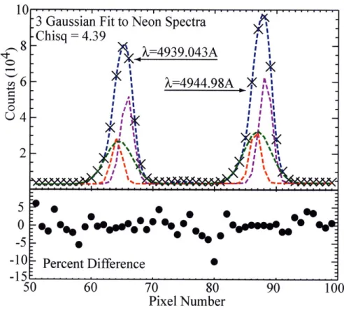
Brightness calibration method for the poloidal pe Filter function calibration data . . . ... Fit to neon calibration lines . ...
Layout of the C-Mod DNB ...
. . .. . . . . . 68 .. . . . 73 . . . . . . . . . 75 s of sight ... 76 .. . . . . . 77 .. . . . 79 . . . . 80 ts . . . 81 ... . . . . . 84 riscopes ... 85 ... . . . . . 87 ... . . . . . 88 .. . . . 91 1-1 1-2 1-3 1-4 1-5 1-6 1-7 .. . . . . 22 .. . . . 23 . . . . . . . 24 .. . . . 29 .. . . . . 30 .. . . . . 32 .. . . . . 33 3- 1 3-2 3-3 3-4 3-5 3-6 3-7 3-9 3-10 3-11 3-12 3-13
3-14 Geometry of DNB ... ... 93
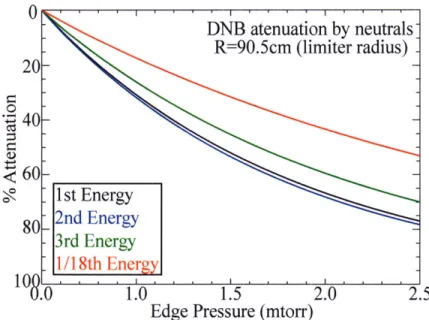
3-15 Stopping cross-sections for DNB attenuation on neutrals ... 94
3-16 DNB attenuation by neutral gas . ... . 96
3-17 Total stopping cross-section for a hydrogen beam in a deuterium plasma 97 3-18 DNB attenuation into C-Mod plasmas . ... 97
3-19 Effective emission rate for CX into the A=4944.67A n=7-6 spectral line 98 3-20 Active CXRS spectra ... ... 100
3-21 Energy level splitting due to the Zeeman effect . ... 103
3-22 Parameterization of the Zeeman splitting by polarization components 106 3-23 Geometry for cross-section effect calculation . ... . . 109
3-24 Cross-section effects on C-Mod CXRS spectra . ... . 110
4-1 C-Mod CXRS velocity sign convention . ... 116
4-2 Estimation of the Ti based on measured Te and TB profiles ... 120
4-3 Power balance determined position of LCFS in an EDA H-mode . . . 124
4-4 Ohmic BVI toroidal velocity profiles . ... . . 125
4-5 Ohmic B5+ poloidal velocity profiles . ... . . 127
4-6 Ohmic L-mode boron temperature and density profiles . ... 128
4-7 CXRS profiles in reversed field, LSN, ELM-free H-mode ... 130
4-8 CXRS and TS temperature profiles in an ELM-free H-mode .... . 131
4-9 Inverse gradient scale lengths in ELM-free H-modes ... 132
4-10 Pedestal evolution in forward field, USN, ELM-free H-mode .... . 133
4-11 CXRS profiles in an EDA H-mode plasma . ... 135
4-12 Pedestal evolution during L-H transitions . ... . . 138
4-13 Toroidal rotation versus plasma stored energy . ... 139
4-14 Pedestal poloidal velocity versus pedestal T . ... 140
4-15 Te and TB profiles in EDA H-modes ... ... 140
4-16 CXRS results in I-mode plasmas ... . . 142
4-17 Pedestal evolution in L-I and I-H transitions . ... 144
4-19 Radial profiles of toroidal velocity precursor to I-H transitions 5-1 5-2 5-3 5-4 5-5 5-6 5-7 6-1 6-2 6-3 6-4 6-5 6-6 6-7 6-8 150 153 155 157 158 160 161 Er profiles in Ohmic L-mode discharges . ...
Evolution of Er and E, shear in ELM-free H-modes . . . . Contributions to Er in ELM-free H-modes . . . ... E, and E, shear in EDA H-modes ...
Contributions to Er in EDA H-modes . ... Full plasma E, profile . . ...
E, and Er shear in I-mode plasmas ...
Scaling of Er well width with theoretical predictions . . . . Width of H-mode Er well as a function of machine size . . Depth of Er well versus plasma confinement (H89) . . . . . Depth of the E, well versus edge pedestal parameters . . . Plasma collisionality in different plasma regimes . . . . Comparison of EDA E, profile to neoclassical theory . . . Main ion diamagnetic contribution to Er . ...
Main ion velocity perpendicular to the total magnetic field
6-9 Radial alignment of Er profiles with electron pedestal parameters
. . . . . . 165 . . . . 167 . . . . . . 169 . . . . . . 171 . . . . . . 173 . . . . . . 174 .. . . . 176 . . . . . . 176 . . . . 146 179
List of Tables
2.1 Theoretical scalings of Er well width . ... 65 3.1 Neutralization Efficiency for Beam Energy Components ... 92 3.2 Beam energy component contributions to CXRS emission ... 99
Chapter 1
Introduction
Ovi r the last quarter century the fusion community has made significant progress toward making magnetic confinement fusion a physically and economically viable energy resource. Advances in physics understanding and reactor engineering have enabled the design of ITER; a fusion experiment which will demonstrate the feasibility of commercial fusion energy by creating the first self-sustaining fusion plasma on earth. In order to reach its operational goals, it is thought that ITER must operate in a plasma regime called high confinement mode, or H-mode, which is characterized by a factor of two improvement in plasma energy confinement over the more easily obtained low confinement mode, or L-mode. However, despite intensive study by both the theoretical and experimental fusion communities, the actual mechanism by which the transition from L-mode to H-mode takes place remains unclear.
The onset of an H-mode is characterized by a sharp decrease in edge fluctuations and the formation of edge transport barriers (pedestals) in both the ion and electron temperature and density profiles. These barriers lead to significant increases in core confinement as a result of temperature and density profile stiffness. It is commonly acc epted that ExB velocity shear is responsible for the suppression of edge turbulence, which reduces the losses of both energy and particles across magnetic field lines and resuilts in the formation of the edge transport barriers and H-mode confinement[l, 2]. However, the self consistent evolution of the radial electric field profile, pedestal shape, and, improvement in plasma confinement are not well understood.
Experimentally, it is clear that core plasma confinement is directly connected to, if not controlled by, the edge pedestal[3, 4, 5]. Plasma rotation and velocity shear are known to play an important role in the transition from L-mode to H-mode with the plasma spin up at the transition propagating from the plasma edge to the core[G6, 7].
The source of this seemingly spontaneous rotation is unknown, though it may be con-nected to scrape off layer (SOL) flows, which couple across the last closed flux surface (LCFS)[8]. This spontaneous edge rotation may be responsible for the formation of shear in the radial electric field profile, thus initiating the suppression of turbul ence and enabling the transition to H-mode. Measurements of flows and radial electric field behavior in the pedestal region may help answer these questions and provide the missing link between the SOL and core observations. A better understanding of the role the radial electric field plays in pedestal physics should enable better control of edge transport and improve core plasma confinement.
On Alcator C-Mod a new pedestal charge exchange recombination spectroscopy (CXRS) diagnostic has been installed, which provides measurements of pedestal pa-rameters (flows, temperatures, densities) and radial electric field structure and be-havior with millimeter radial resolution and 5 millisecond temporal resolution. rT he
radial electric field is determined through the radial force balance equation
1 &p
E, = r - v,iB + vo,iB ([.1)
niZie ar
where the subscript, i denotes species, Z, n, and p are the charge, density, and pressure, voe, and B0e, are velocity and magnetic field in the poloidal and toroidal
directions. CXRS measurements, coupled with knowledge of the magnetic fields, provide all of the information necessary to determine E, from equation 1.1. Details of the new CXRS system will be given in chapter 3.
These C-Mod pedestal E, measurements are made in a unique and relevant pa-rameter regime and can thus bring new information and understanding to the fluion community. Most C-Mod discharges are free from any externally applied torque and operate at ITER-like magnetic fields (~5T) and plasma pressures (1MPa).
Ad-ditionally, at high density, the C-Mod pedestal has ITER-like opacity to neutrals and thermally equilibrated electrons and ions, conditions currently unique to C-Mod. This thesis employs the results from the new CXRS system to probe the relationships between the radial electric field, L-H transitions and plasma confinement.
1.1
Alcator C-Mod Tokamak
Alcator C-Mod is a high-field, compact toroidal device, located at the Plasma Science Fusion Center (PSFC) at MIT. C-Mod has been at the forefront of the US fusion research program for over a decade and is uniquely suited for studying ITER relevant plasmas due to the similarities between the two devices. C-Mod, shown in Fig. 1-1 is a relatively small device compared to other tokamaks. It has a major radius of 0.67m and minor radius of 0.22m. Although ITER will be nine times larger than C-Mod they share many similar characteristics such as toroidal magnetic field strength, plasma density and pressure, aspect ratio, plasma shape, and divertor geometry.
C-Mod typically runs with core densities between 1 and 5x10²⁰m-3 and with
plasma pressures up to 1.8 atm. Core plasma temperatures are of order a few keV and the plasma current is typically between 0.6 and 1.2 MA; although plasma cur-rents as low as 0.4MA and as high as 2MA can be achieved. The standard operating magnetic field is 5.4T at the magnetic axis, but C-Mod is capable of operating any-where between 2 and 8T. The heating scheme on C-Mod is ion cyclotron resonant frequency (ICRF) heating, typically at 78 to 80 MHz. This frequency is resonant with the cyclotron frequency of the ions at a magnetic field of 5.3T, which places the bulk of the input power on axis for a standard C-Mod shot. It is also possible to provide adequate heating for alternate magnetic fields strengths by switching to alternate frequencies such as 50 or 70MHz.
All of the data presented in this thesis are from the C-Mod 2007 and 2008 run campaigns. During these campaigns there were two dipole ICRF antennas at D and E port, and one four strap antenna at J-port, see Fig. 1-2 for port geometry. These antiennae together were capable of coupling up to 6MW of power into the plasma. In
Figure 1-1: The Alcator C-Mod tokamak
addition to the ICRF antennae there was also a single lower hybrid (LH) current drive antenna installed at C-port, which coupled up to 1MW of power into the plasma at 4.6GHZ. Neither of these systems act as a particle or momentum source.
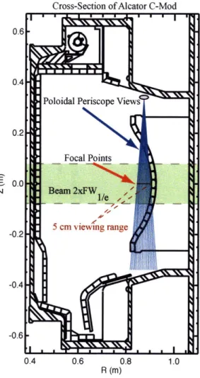
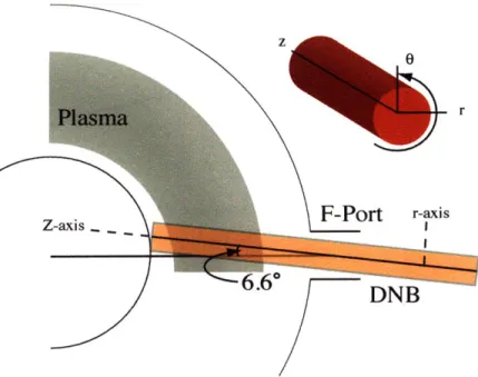
There are no neutral heating beams on C-Mod. Instead there is a diagnostic neutral beam (DNB) located at F-port. The beam has a predominantly radial tra-jectory with only a slight 6.4 degree toroidal angle and is horizontally injected into the plasma at mid-plane (Z=0), see Fig. 1-3. It is capable of producing a 7A, 50keV, hydrogen beam for a total of 1.5s, either steady or modulated. Due to the low beam current, radial injection angle and the high level of beam attenuation into C-Mod's high density plasmas, the DNB is not a significant source of either momentum or particles. More detailed information on the DNB is provided in 3.
In Fig. 1-3 the horizontal cross-section of the Alcator C-Mod tokamak is displayed with a typical C-Mod plasma shape outlined in red. C-Mod is a diverted tokamak; it is designed to operate with a null or x-point in its magnetic field topology. The
Figure 1-2: Top view of the Alcator C-Mod tokamak
VERTICAL UPPER COVER EF COILS HORIZONTAL PORTS I LOWER COVER CRYOSTAT PL OH COIL
.iv
TF MAGNET CYLINDER - UPPER DIVERTOR LOWER DIVERTORASMA LAST CLOSED FLUX SURFACE
Figure 1-3: Horizontal cross-section of the Alcator C-Mod tokamak showing the size and positions of the tokamak support structure and geometry. A typical plasma shape is shown in red.
magnetic flux surface with the null point is referred to as the last closed flux surface (LCFS) or separatrix. Magnetic surfaces inside of the LCFS are "closed", meaning they end on themselves, and surfaces outside the LCFS are "open", meaning they ternminate on walls or other plasma facing components. The region of plasma that exists on open field lines, outside the LCFS, is referred to as the scrape off layer (SOL). To create magnetic topologies that have a null point (or null points), the plasma is shaped using EF coils see figure 1-3, resulting in an elongated 'D' shaped plasma rather than a circular cross-section plasma.
When the minull point in the magnetic field is positioned by the lower divertor the plasma shape is referred to as lower single null (LSN). When the null point is positioned by the upper divertor, the plasma shape is referred to as upper single null (USN), and when there are two null points in the field, one by each divertor, then the plasma shape is said to be in double null (DN). The divertors are designed to place
the strike points of the LCFS and open magnetic flux surfaces, on surfaces that can handle high heat fluxes and are positioned in such a way as to minimize the amount of impurities that work their way into the plasma. On C-Mod most of the plasma facing components, located at the inner wall, limiters, and the divertor plates, are covered primarily in molybdenum tiles, which have a melting point of 2617 degrees celsius. C-Mod plasmas can also be run in a limiter configuration, limited typically on the inner-wall, not making use of either the upper or lower divertor. In fact, the start, up shape for all C-Mod plasmas is inner-wall limited.
Often the magnetic field topology of a discharge is referenced by the direction of particle drifts in the plasma, such as the B x VB drift direction, rather than by the physical location of the X-point, as in USN or LSN. The reason for this is that the drift, direction provides more information about the magnetic field than the magnetic topology. In the presence of a magnetic field that has a gradient perpendicular to the field direction, as is the case in a tokamak, a charged particle feels a force that is perpendicular to both the field and the gradient. This particle velocity as a result of this force is given by
1 mj B x VB 2,
VBxVB - 2 B B2 (1.2)
2 ejB B2
where B is the magnetic field, my is the mass and ej the charge for particle j, and vI is the perpendicular velocity of the particle. Note, that the B x VB drift direction is different for ions and electrons. Experimentally, it has been found that discharges with the X-point in the direction of the ion B x VB drift require less input power to initiate an L-H transition than do discharges with the X-point in the direction of the electron B x VB drift. For this reason, the ion drift direction is considered the "favorable" B x VB direction and the electron the "unfavorable". In standard C-Mod discharges (forward field) the magnetic field is in the clockwise direction from a top down view of the machine. Thus when operating in forward field, LSN discharges are in the favorable B x VB direction and USN unfavorable. This switches when the direction of the magnetic field is reversed (the plasma current direction is always
reversed with the toroidal field in C-Mod).
There are two other plasma particle drifts that are relevant to this thesis, the diamagnetic drift and the ExB drift. The diamagnetic drift is the particle motion
that results from the force of the plasma pressure and is given by BxVp
vY -- e 2 (1.3)
Here, B is the magnetic field, ej is the charge on the particle and p and n are the
plasma pressure and density. Again, note that the drift is dependent upon the sign of the charge, meaning the ion and electron directions are opposite. These directions also switch when the magnetic field is reversed. In forward field, on the low field side of the tokamak, the electron diamagnetic direction is vertically upward and the ion diamagnetic direction is downward. The diamagnetic directions are often used when describing the direction of observed flows in a plasma. Lastly, a charged particl:, in a magnetic field will feel an additional force when there exists an electric field (E) perpendicular to B. This force results in the ExB velocity drift and it is the shear in this quantity that is believed to be responsible for breaking up turbulent eddies and improving plasma confinement[2, 9]. Therefore, this drift is very important to this thesis, and a detailed discussion of its relationship to turbulence and plasma confinement will be given in chapter 2. The drift is given by
ExB
VEzB -- B (.4)
B2
and is charge independent.
1.1.1
C-Mod Diagnostics
C-Mod has a fairly comprehensive suite of plasma diagnostics[10], only a subs(let of which are relevant to this thesis. A summary of the diagnostic systems, the data f'rom which was used in this work, is given here. The main diagnostic tools for measuring the electron density and temperature in the plasma are the Thomson scattering (TS) systems of which there are two: an edge system covering from r/a of 0.8 to r/a of 1 .05
and a core system, which covers from r/a of 0 to 0.8. The edge TS system provides Te and ne profiles covering the pedestal region with millimeter spatial resolution and a time resolution of 20ms. For more information on the C-Mod TS systems one should refer to reference[11l. The average Zeff in the plasma is obtained through a comparison of the visible bremsstrahlung emission (oc n 2Zeff/ T) with Thomson
scattering electron density and temperature information.
Edge neutral pressures are measured at several toroidal points throughout the tokamak using standard pressure gauges. These diagnostics provide data on a 5-10 milli-second time scale and have an accuracy 0.1mtorr. Magnetics measurements, emplloying voltage loops, flux loops, and Rogowski coils enable the reconstruction of the magnetic equilibrium through the EFIT code [12]. EFIT uses the data to find a best, fit solution to the Grad-Shafranov equation for the C-Mod tokamak geometry. The outputs of the EFIT code include magnetic flux surfaces on an R-z grid, the polidal magnetic field, plasma current and q profiles. EFIT is run for every shot on a, standard 20ms time base. However, if desired, it can be run on a faster time base. It is also possible to run kinetic EFIT analysis of plasma discharges, which uses the measured plasma density and temperature profiles to calculate a self-consistent magnetic equilibrium as a function of time. However, this is difficult to do and is not performed routinely for C-Mod discharges.
In addition to the CXRS systems, impurity ion temperature, density and velocity measurements are also provided by core viewing soft X-ray diagnostics, such as Hirex Jr.[13] and Hirex SR[14], which diagnose mainly argon and molybdenum. These profiles typically have a temporal resolution of 20ms, and extend from the plasma core out to r/a between 0.7 and 0.85 depending on signal level. C-Mod also has a number of fluctuations diagnostics including reflectometry, phase contrast imaging (PCI), D-alpha, gas puff imaging (GPI) and magnetics. These systems together monitor the magnetic and density turbulence fluctuations in both the core, edge, and SOL regions of the plasma. More information on these systems can be found in reftrence [10].
1.2
Plasma Operating Regimes
There are several distinct operational regimes that are observed on the Alcator C-Mod tokamak. These include the L-mode and a number of different types of high confinement regimes. Of these regimes, there are two types of H-modes that are routinely run on C-Mod, the EDA (enhanced D-alpha) H-mode [15, 16] and the ELM (edge localized mode) free H-mode[5]. It is also possible to run ELMy H-modes on C-Mod. However, no data from this type of discharge will be used in this thesis and so the details of this operating regime will not be discussed. In addition to H-modes a new operational regime, the improved L-mode (I-mode), has recently been develolped on C-Mod. The I-mode has H-mode like energy confinement coupled with L-m1rno)de like particle confinement and will be described in detail in this thesis.
1.2.1
EDA H-modes
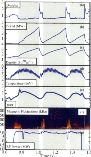
Enhanced D-alpha (EDA) H-modes are one of the most common types of H-modes run on C-Mod. They are quiescent H-modes without ELMs, characterized by increased particle transport through the edge relative to ELM-free H-modes. This increase in edge transport can be observed through the increase in Da emission during the H-mode period as shown in Fig. 1-4a. The enhanced particle transport is associated with a quasi-coherent mode (QCM) observed on the density and magnetics fluctuationls at frequencies between 80 and 150kHz. The QCM develops shortly after the formation of the edge pedestals, is localized to the electron density pedestal and is likely the result of a resistive ballooning instability. It is believed to be the density pedestal release mechanism that prevents impurities from accumulating in the core and increasing the radiated power. The increased particle transport allows for steady state H-mode operation with constant radiated power, density, temperature, and confinement. Fig. 1-4 shows the steady state nature of these parameters for a typical EDA H-mode. The QCM, and thus EDA H-modes, are only observed in high collisionality plasumias, typically v* >1 at the top of the pedestal, where v* is calculated according to
12 Time (s)
Figure 1-4: Characteristics of a C-Mod EDA H-mode (Shot=1080321020) (a)D" (b) radiated power (c) line averaged density (d) electron temperature (e) plasma confine-ment factor H89, (f) magnetic fluctuations, (g) input ICRF power
qRvei
V* = (1.5)
6 2 Vth,e
Here, q is the local safety factor, R the major radius, vi is the electron ion collision frequency, E is the inverse aspect ratio, and Vth,e is electron thermal velocity.
1.2.2
Edge localized mode (ELM) free H-modes
ELM-free H-modes are inherently transient, characterized by a strong particle trans-port barrier. This barrier results in impurity accumulation during the H-mode, which eventually causes its radiative collapse. Both the plasma and impurity density in-crease monotonically during ELM-free H-modes, while Te, Ti, and energy
confine-2.0 1.5 1 0 RFPower(MW) 0 .6 0.8 1.0 1.2 1.4 1.6 Time (s)
Figure 1-5: Characteristics of a C-Mod ELM-free H-mode (Shot = 1070726015) (a)Da (b) radiated power (c) line averaged density (d) electron temperature (e) plasma confinement factor H89, (f) magnetic fluctuations, (g) input ICRF power
ment peak early and then degrade as a result of the increasing radiated power. These characteristics are shown in Fig. 1-5. Edge L-mode density and magnetic fluctuations are sharply suppressed at the onset of ELM-free H-modes, while the residual fluctu-ations during the H-mode are largely incoherent [Fig. 1-5(f)]. The best ELM-free H-modes can have energy confinement in the beginning of the H-mode up to :30% higher than the best EDA H-modes and much higher particle confinement. However, as the radiated power approaches the input power, the plasma energy confinement and temperature pedestal both decline[17, 18].
1.2.3
Improved L-mode (I-modes)
Standard L- to H- transitions on Alcator C-Mod occur on a sub-millisecond time scale. This is too fast for the current CXRS system to capture any of the transi-tioni dynamics. However, C-Mod discharges with the X-point in the unfavorable ion
B x VB drift direction with input power just below the H-mode threshold can
ex-hibit slower evolution prior to L-H transitions. The slow evolution enables insight into the H-mode physics through examination of the plasma evolution preceding the transition. The slowly evolving plasma phase is not a new phenomenon, it has been observed previously on both C-Mod[3, 19] and ASDEX Upgrade[20], but always as a transient event. Recent experiments on C-Mod have developed this transient period into an operational regime that can persist for many energy confinement times[21].
This regime is characterized by an L-mode-like edge particle barrier, but an H-mode-like energy barrier and has been termed an 'improved L-mode', or 'I-mode'. In I-mode the plasma density increases modestly coincident with the application of ICRF power, but does not increase further or approach its H-mode values. The plasma temperature, however, approaches and maintains close to its full H-mode value during the I-mode period. These features can be seen in the core plasma traces shown in Fig. 1-6. The key differences between L-, I-, and H-mode plasmas are illustrated in Fig. 1-7, which displays the edge electron temperature and density pedestals in these regimes. Here, the I-mode electron temperature pedestal approaches a full H-mo(e pedestal, while the electron density pedestal remains significantly closer to its L-node levels. Similar behavior is observed in the corresponding B5+ temperature
and density pedestal profiles.
The I-mode evolves smoothly from L-mode plasmas after the application of ICRF heating. There is no apparent bifurcation or clear transition point. Although the I-mode appears to be an intermediate state between L-I-mode and H-I-mode, the transition from I-mode to H-mode remains an apparent bifurcation, only after which an H-mode density pedestal forms. During I-mode, H-mode like plasma confinement (H98 0.8) is maintained concomitant with H-mode like plasma temperatures, Fig. 1-6(e).
1.0
Time (s)
Figure 1-6: Characteristics of a C-Mod I-mode plasma (Shot = 1080416021). The grey highlighted region indicates the I-mode portion of the discharge. (a)D, (b) radiated power (c) line averaged density (d) plasma temperature (e) plasma confinement factor H98, (f) magnetic fluctuations, (g) input ICRF power
The improved confinement can be maintained in steady state. L-mode like particle confinement prevents the buildup of impurities and consequently the accompanying increase in radiated power. The steady state operation in I-mode is associated with an edge turbulence mode observed on the density and magnetic fluctuations with a frequency around 100kHz as shown in Fig. 1-6 (f). The mode appears to be similar to the QCM observed in EDA H-mode operation, but exists at much lower collisionality
800 L-mode a ic I-mode • H-mode a 600
4
" :----1.-- - -- . . 400 (a) 2.0 1.5 E 1 .. 1.0 -0.5 (b) 0 - -- -- --- -- -- --- ---3 -2 -1 0 Distance from LCFS (cm)Figure 1-7: Comparison of the edge electron temperature (a) and density (b) profiles between L-mode, I-mode and H-mode.
1.3
Thesis Goals and Outline
The objective of this thesis is to acquire a better understanding of the connections between E,, E, shear and plasma particle and energy confinement. This informal:ion will lend itself to determining the physics of the L-H transition, comparing to theo-retical predictions of E, formation, and discerning the important factors that co trol pedestal shape and structure. To accomplish these goals this thesis will utilize the data from the new edge CXRS diagnostic to characterize the structure and behavior of the radial electric field in the edge pedestal region in a wide variety of plasma configurations and regimes.
Chapter 1 provides an introduction to the theme of the thesis and motivates the importance of the work. It gives sufficient background information on Alcator C-Mod, available diagnostics, and plasma regimes to provide a basis from which the discussions of subsequent chapters can be understood.
Chapter 2 discusses in detail the status and history of L-H transition theories, especially where it relates to radial electric field formation and behavior. It also introduces the concepts of ExB shear suppression, which is an integral part of this work. Lastly, it outlines the experimental work that has been performed on other machines in pursuit of a better understanding of the role E, plays in high confinement plasmas.
Chapter 3 describes the details of charge exchange recombination spectroscopy as a plasma diagnostic. It begins with the physics behind the measurement, introduces the diagnostic setup on C-Mod and concludes with the data analysis techniques l.sed to analyze the data presented in this work.
Chapter 4 presents the experimental results of the edge CXRS system. The ob-tained impurity ion temperature, velocity, and density profiles are introduced and their general characteristics and behaviors are described.
Chapter 5 presents the structure and behavior of the edge radial electric field, as determined from the CXRS data, in a variety of plasma operational regimes aund examines its relationship to both particle and energy confinement.
Chapter 6 illustrates the relationship between the H-mode radial electric field and plasma parameters. It also examines the behavior of the main ion population in the pedestal region and discusses the implications C-Mod radial electric field measure-ments have for Er formation, L-H transition, and pedestal structure theories.
Chapter 7 summarizes the results and main points of the thesis and discusses the next steps in pursuing this research.
Chapter 2
Tokamak Edge Radial Electric
Fields: Theory and Experiment
Since the discovery of the H-mode on the ASDEX tokamak in 1982, numerous theo-retical models have been proposed to explain the sudden plasma transition to a higher energy confinement state. Many of the models can not explain all of the observed phenomenology surrounding the L-H transition including particle and energy barrier formation, plasma flows, radial electric field formation and structure, turbulence sup-pression, and the extremely fast time scales. Some models have been refuted explicitly by experimental results and still others remain contenders to explain, at least in part, the wide range of phenomenology observed across the many different fusion devices. Unfortunately, many of the models do not provide predictions that are conducive to experimental testing, which makes comparisons to theory difficult or impossible. This chapter will attempt to summarize both the theoretical and experimental work done to (ldate on L-H transition and pedestal formation theories with a focus on those that touch upon the edge radial electric field.
2.1
Early Theories
The(0 first observations of the H-mode were made in the early 1980's in diverted toka-maks, namely, ASDEX [22], Doublet III (DIII) [23], and the Princeton Divertor
Ex-periment (PDX) [24]. Since that time, H-modes have been observed in many different magnetic configurations and seem to be a phenomenon ubiquitous to tokamak plas-mas. However, the early observations of H-mode plasmas were observed concomil ant with diverted plasma geometries and lead theorists to focus on such topics as electrical and thermal properties of the divertor channel [25] and edge magnetic shear st Abi-lization of turbulence [26]. These theories were mainly speculative in nature, seeking plausible explanations for the observed phenomena consistent with the experimental information available at the time.
In 1985 Hinton proposed a model for the L-H transition in which the ion transplort was assumed to be neoclassical and the electron behavior was influenced by the ions [27, 28]. For the high ion collisionality case the radial ion heat flux was found to depend upon the location of the active X-point, with the flux significantly reduced if the X-point is in the favorable B x VB direction. The model purports to show that in this magnetic geometry large ion temperature gradients can develop at the edge and the L-H transition occurs at a critical, though non-specified, value of the radial ion heat flux. The model also predicts that an L-H transition can take place regardless of magnetic topology if the input power is sufficient to bring the edge ions into the low collisionality regime. In this way, Hinton explains the observed differences in the L-H transition power threshold between the unfavorable and favorable drift direct, i'ns.
However, Hinton's theory is vague on the specifics of the L-H transition trigger and does not give testable predictions on the pedestal shape, except to say that the c dge ion temperature gradient scale length should be of order one ion banana width. The model also does not address the density pedestal formation and does not address how the ion dynamics couple to the electrons over the wide range of collisionalities considered, though the radial electric field is cited as a possible mechanism.
Other early L-H transition theories were developed through consideration of toka-mak stability properties to a variety of known instabilities and turbulence mecha-nisms, including ideal ballooning and interchange modes [29], tearing modes [30] and resistive fluid turbulence and resistive kink modes [31]. Bishop, in 1986, considered the effect that divertor geometry, specifically the existence of a separatrix, has on
ideal ballooning and interchange instabilities in H-mode edge pressure gradients [29]. In this work he proposed that the existence of a current localized inside the separatrix could act to stabilize pressure driven modes by altering the local magnetic shear. In L-nm ode the edge temperature gradient is small as is the edge current making the edge region unstable to these modes. However, if this current could be increased then the edge region could be made locally stable enabling a positive feedback cycle and the sustainment of a temperature barrier.
Hahm and Diamond considered the effects of resistive turbulence in diverter ge-ornmetry on the formation of the edge transport barrier [31]. They found that the increase in edge magnetic shear associated with a separatrix [26] has a larger effect on resistive pressure and resistivity gradient driven modes than it does on the ideal modes previously examined by Bishop, and that the ideal ballooning stability limit is not the only contributor to H-mode dynamics. The paper demonstrated that diverter geometry, through increased magnetic shear, reduces the step size of the resistive fluid turbulent diffusion processes, improving plasma confinement and stabilizing resistive kink modes near the LCFS. Hahm and Diamond propose two possible scenarios for the L-H transition, both of which rest on the idea that the improved confinement in diverted discharges enhances the edge plasma's stability against pressure driven modes and enables the plasma to support steeper edge gradients. Neither of these scenarios, however, represent a bifurcation as indicated experimentally.
Beginning in the late 1980's L-H transition theories began to focus on the radial electric field as a potential hidden variable that could have bifurcated states and thus act as the causal mechanism for L-H transitions. In 1988 Shaing published a neo-classical transport theory that included electric and magnetic fluctuations in which the electron and ion particle and heat fluxes were explicitly calculated and found to depend on the electrostatic potential, 4 [32]. Shaing proposed that a change in E,
(Er - -V(D) would cause the radial ion and electron particle fluxes to become
un-balanced, inducing a change in the turbulence frequency and wave number spectrum that would act to keep the plasma quasi-neutral. If the change in the radial electric fieli were to a more negative value then the corresponding change in the turbulence
could lead to an improvement in both particle and energy confinement [32]. This and Shaing's later works considered the evolution of turbulence in the presence of a constant sheared electric field [33, 34] (sheared ExB flow) and concluded that the turbulence is suppressed by positive E, shear (_E- > 0), a result that occurs diu to the inclusion of diamagnetic effects in the analysis.
2.2
ExB turbulence suppression
Perhaps the most well known piece of L-H transition theory is the ExB shear sup-pression model. Although not proven, this model is widely accepted due to the great success it has had at explaining a large variety of observed plasma transport phe-nomena [2, 35]. The foundations for this model were provided in 1990 by Biglari, Diamond and Terry (BDT) [1], who showed that sheared poloidal flow leads to the suppression of turbulent transport through a reduction in the radial correlation length of the turbulence and that this effect is independent of the sign of both the radial electric field and its shear.
The BDT model was not the first to consider the effect of sheared flow on tur-bulence. The work of Shaing [32], which was discussed in section 2.1, was published first and both Shaing and Biglari had as their predecessor the work of Chinuh et
al[36], which considered the effect of a sheared radial electric field on collisional drift wave turbulence. All three theories were developed in cylindrical geometry and ExB flow was not differentiated from poloidal flow. In his work, Chiueh assumed that the turbulence perturbations were ballooning like, while the works of Shaing and Biglari consider flute like perturbations.
Like Shaing, the BDT model considers the effect of poloidal flow on edge turbu-lence, however, it comes to very different conclusions. They find that poloidal flow has a shearing effect on turbulent eddies, which acts to de-correlate them without the need to include diamagnetic flow and most importantly, the BDT results are valid regardless of the sign of the flow or of its shear. According to the BDT model the rate at which turbulence is pulled apart by poloidal flow, that is the rate at which two
fluid elements separated by a radial distance Art are separated by a poloidal distance
keot- , is given by
(o = (ketArt) + (2.1)
ar r+
where vo is the poloidal velocity and r+ is the minor radius at which the shearing is taking place. The radial diffusive scattering rate of the turbulence is given by
4D
Awt = r (2.2)
Art2
where, D, is the diffusion coefficient. These two processes together are responsible for the de-correlation of turbulence eddies with the shearing mechanism likely to be the dominant of the two.
The BDT model specifically addresses the strong poloidal flow (or flow shear) regitme in which wc is assumed to be much larger than Aet. Under this constraint the poloidal flow and radial scattering decorelation mechanisms are found to couple and the characteristic turbulence decorrelation time is dependent upon both rates,
T7 =: (2w2At) . The characteristic radial correlation length of the turbulence is givi by
Ar, ( w Art (2.3)
from which one can see that the radial correlation length, Ar, will be reduced from its initial value, Art, if the initial assumption was valid, namely A_ < 1. Thus, the BDT model provides a simple and in principle experimentally testable criterion to determine if the measured sheared poloidal velocity flow is sufficiently large to suppress the turbulence.
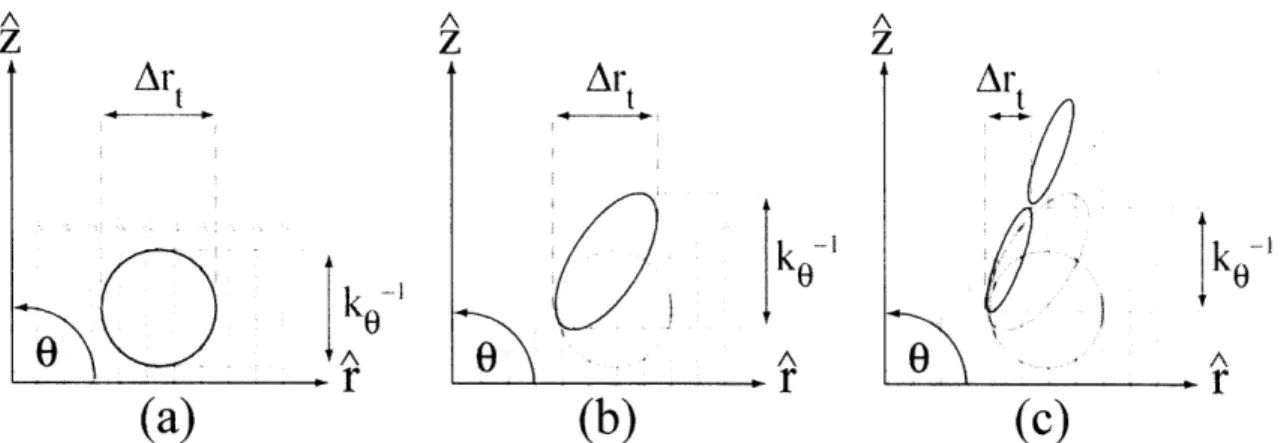
The physical mechanism by which the shearing takes place is actually very simple. Generally, a fluid element in a constant background flow will be carried along by the flow without distorting the shape of the element, see Fig.2-la. However, if shear is added to the background field perpendicular to the direction of flow then the eddy is distorted, being stretched in the direction of the velocity flow and its width (radial
A A A z z z
Ar
tAr
tAr
t A A 0 Ar
r
r
(a)
(b)
(c)
Figure 2-1: (a) An example turbulent fluid element ill the presence of a constant velocity field (b) Distortion of fluid element due to sheared velocity flow (z(r)=ar')(c) de-correlated fluid element due to sufficiently large velocity shear
correlation length) reduced in the direction of the velocity gradient, see Fig. 2-11). If the shear in the velocity flow is sufficiently large then the fluid element can no longer maintain its structure and is shorn apart, Fig.2-1c [35].
The results of the BDT model were derived in cylindrical geometry and as a result there is little differentiation drawn between poloidal flow (vo), ExB flow (VE), a11( the total flow perpendicular to the imagnetic field (v ). This causes confusion as to which flow is actually important in the turbulence decorrelation process [2, 1]. The answer to this puzzle was provided by Kimi ct al [9] who, while extending the theory of ion-temperature-gradient-driven turbulence to the banana-plateau regime, derived to second order and in general toroidal geometry the equations governing the evolution and propagation of flute like energy and density fluctuations. In this work, Kim shows explicitly that these fluctuations are convected only by vE and that the diamnagnetic flow (Eq. 1.3) does not contribute. As such, all subsequent modifications to the BDT model consider specifically the effect of ExB velocity on turbulence.
The extension of the BDT model to full toroidal geometry was considered by Hahm for the cases of both circular cross-section [37] and arbitrarily shaped tokanuak plasmas [38]. In these works Hahmn considered not only the effect of vE, which is important at the edge, but also parallel flow shear, vil, which caill be important in the core of tokamak plasnmas (e.g. internal transport barrier theory). In doing so, Hahnm lderived more complicated expressions for the flow shear rate, which improve the
original cylindrical approximation in that they correctly take into account the effects of magnetic shear. For the case of circular cross-section plasmas [37] the rotation shear rate is given by
2 t22 qVE 2 2 2 (r4
S A 2
1dr
rJ
Aq2ar
rR)where A and Ar are the toroidal and parallel correlation angles of the turbulence and q is the safety factor. For flute like perturbations, which align themselves along the magnetic field and so have Al > 1, only the first term in equation 2.4 is important and given that the toroidal angle of the fluctuations is almost the same as the magnetic field angle, A -_ q (rket)-' [38], the rotational shearing rate can be represented in
the more familiar form
W (ketArt)
(
(2.5)
Note that in the case of weak magnetic shear, this result reduces to the cylindrical resilt given in equation 2.1. In practice the poloidal and radial scale lengths of the turbulence are assumed to be approximately equal and so the coefficient in equation 2.5 is set to 1. In toroidal geometry, the radial correlation length is again found to be related to the ratio of w, to Awt though the dependence is different
Arc Art (2.6)
As in the cylindrical approximation, the turbulence radial correlation length becomes significantly reduced when the rotational shearing rate Eq. 2.4 is greater than the dif-fusive radial scattering rate, which in toroidal geometry is given by Awt = 4DO (-zq)2
Flow shear can act to reduce turbulent radial transport not only by reducing the turbulence radial correlation length, but also by altering the cross-phase between the temperature, density, and potential fluctuations [39, 40, 41]. The radial fluctuation driven particle flux, P, and energy flux, Q, are composed of electrostatic and magnetic components that depend upon the cross-phase of the relevant fluctuating quantities.
The fluxes are given by [41]
(Eo tn) (Jiibr) (7)
BO eB O
and
3 {nj (T) + Tj (Eol ) (2-8)
Here the subscript j denotes species, the fluctuating quantities are the electric field (E), the density (n), the temperature (T), the magnetic field (b), and the current (J). Directional subscripts are with respect to the magnetic field (B), the angles brackets denote averages on a flux surface (assuming circular flux surfaces), and kb is Boltzman's constant. The factor 92,e can be determined from g2e Xe l
where XeIl is the classical parallel thermal diffusivity.
The flux dependence on the cross-phase can be seen by writing out the contribu-tions explicitly, for example, the electrostatic contribution to the particle flux is given by
,E (E0 (n2) COS En
E (2.9)
where OEn is the relative cross-phase between the density and potential fluctuations [40]. From equation 2.9 it is clear that the electrostatic contribution to the particle flux can change sign, be completely negated, or completely unaffected depending on the cross-phase of the fluctuations. Carreras and Ware have both shown that for resistive pressure gradient driven turbulence (RPGDT) ExB velocity shear an(d its derivatives can affect the cross-phase of the turbulence and thus alter radial transplort
[39, 42]. As yet, there is no complete theory on the effects of sheared ExB flow on the cross-phase of turbulent fluctuations.
2.3
Two-Step Theories
Many E, based L- to H- transition theories are "two-step" theories: step one, the formation of a radial electric field and step two, the suppression of edge turbul:ence
via ExB shear. These theories can be categorized roughly by the proposed method of radial electric field formation. From examination of equation 1.1, one can see that there are two main feedback mechanisms by which the radial electric field can be altered: the VxB term and the pressure gradient term. Many theories have focused on the poloidal velocity contribution (voBo) to E,, in large part due to experimental observations of evolution in this quantity (impurities not main ions) prior to L- to H- transitions. The details of these observations will be discussed in section 2.6. Transition theories that require the poloidal velocity to be the dominant contribution to ;, at the time of the transition are referred to as poloidal spin-up theories and those that rely upon the diamagnetic contribution to E, as pressure gradient theories. Poloidal spin-up theories will be discussed in sections 2.3.1, while pressure gradient theories will be addressed in section 2.3.2. Many of the following theories seek to identify a"trigger" mechanism for the L-H transition focusing, typically, on only one aspect of the plasma dynamics. As the plasma flows, pressure gradients, heat and part:icle fluxes, turbulence, and radial electric field are intimately connected they must be evolved self-consistently to determine reliably a causal mechanism for the L-H transition. Thus, the term "trigger" in these theories can be misleading and in the following discussions will only be used to indicate the dominant contribution to E, at any given time.
2.3.1
Poloidal Spin-up Theories
Ion Orbit LossThe first of the poloidal spin-up theories was developed by Shaing and Crume who, motivated by experimental results [43, 44] which indicated the presence of a negative electric field in H-mode plasmas, proposed a mechanism by which E, could become more negative and lead to the transition [45, 46]. Namely, the loss of ions at the edge due to the intersection of their orbits with open field lines or limiter surfaces results in the formation of a negative radial electric field. By balancing the poloidal angular momentum imparted to the plasma as a result of ion orbit losses against