HAL Id: hal-02984084
https://hal.archives-ouvertes.fr/hal-02984084
Submitted on 30 Oct 2020
HAL is a multi-disciplinary open access
archive for the deposit and dissemination of
sci-entific research documents, whether they are
pub-lished or not. The documents may come from
teaching and research institutions in France or
abroad, or from public or private research centers.
L’archive ouverte pluridisciplinaire HAL, est
destinée au dépôt et à la diffusion de documents
scientifiques de niveau recherche, publiés ou non,
émanant des établissements d’enseignement et de
recherche français ou étrangers, des laboratoires
publics ou privés.
engineering the sign of the bias field in orthogonal
bilayers by a magnetically switchable response
mechanism
Alberto Bollero, Volker Neu, Vincent Baltz, David Serantes, José Luis F
Cuñado, Javier Pedrosa, Ester Palmero, Marietta Seifert, Bernard Diény,
Rafael del Real, et al.
To cite this version:
Alberto Bollero, Volker Neu, Vincent Baltz, David Serantes, José Luis F Cuñado, et al.. An
extraor-dinary chiral exchange-bias phenomenon: engineering the sign of the bias field in orthogonal bilayers
by a magnetically switchable response mechanism. Nanoscale, Royal Society of Chemistry, 2020, 12,
pp.1155. �10.1039/x0xx00000x�. �hal-02984084�
ARTICLE
a.IMDEA Nanoscience, Madrid, Spain.
b.IFW Dresden, Institute for Metallic Materials, Dresden, Germany.
c. SPINTEC, Univ. Grenoble Alpes / CNRS / CEA / Grenoble INP, Grenoble, France. d.ICMM, Instituto de Ciencia de Materiales CSIC, Campus de Cantoblanco, Madrid,
Spain.
e. Dep. de Física de la Materia Condensada and Instituto "Nicolás Cabrera", Univ.
Autónoma de Madrid, Spain. *E-mail: alberto.bollero@imdea.org
†Electronic supplementary information (ESI) available.
Received 00th January 20xx, Accepted 00th January 20xx DOI: 10.1039/x0xx00000x
Extraordinary Chiral Exchange-Bias Phenomenon: Engineering the
Sign of the Bias Field in Orthogonal Bilayers by a Magnetically
Switchable Response Mechanism
Alberto Bollero, *a Volker Neu, b Vincent Baltz, c David Serantes, d José Luis F. Cuñado, a,e Javier
Pedrosa, a Ester M. Palmero, a Marietta Seifert, b Bernard Dieny, c Rafael P. del Real, d Manuel
Vázquez, d Oksana Chubykalo-Fesenko, d and Julio Camarero d,e
Isothermal tuning of both the magnitude and the sign of the bias field has been achieved by exploiting a new phenomenon in a system consisting of two orthogonally coupled films: SmCo5 (out-of-plane anisotropy)-CoFeB (in-plane anisotropy). This has been managed by using the large dipolar magnetic field of the SmCo5 layer resulting in pinning one of the branches of the hysteresis loop (either the ascending or the descending branch) at a fixed field value while the second one is modulated along the field axis by varying the orientation of an externally applied magnetic field. This means the possibility of controlling the sign of the bias field in a manner not reported to date. Moreover, modulation of the bias field strength is possible by varying the thickness of a spacer between the SmCo5 and CoFeB layers. This study shows that the observed phenomena find their origin in the competition of artificially induced anisotropies on both layers, resulting in a reversible chiral bias effect that allows selecting the initial sign of the bias field by switching (upwards/downwards) the magnetization in the SmCo5 film.
1 Introduction
Magnetic materials are playing a key role in our technological development and they are present in many technological sectors: energy, transport, aerospace, biomedicine, spintronics…1 This latter area keeps indeed a close relation with all the others since mass storage media and magnetoresistive sensors find important functionalities in many technological control and monitoring devices. Paradoxically, these devices are based on a phenomenon – the so-called exchange-bias (EB)– which was discovered in 1956,2 and whose physical origin remains poorly understood at present.3,4 The rapid technological development and miniaturization of devices make necessary to advance in the knowledge and control of the interfacial effects responsible of the EB phenomenon to discover novel effects with added functionalities.3
EB is frequently used in magnetic random access memories and magnetoresistive read heads to pin the magnetization of a
reference layer. Setting EB is usually achieved by cooling a ferromagnetic (F)-antiferromagnetic (AF) bilayer under an applied field through the Néel temperature (TN) of the AF.5 The EB phenomenon typically manifests itself as a unidirectional field shift (EB field) as well as a broadening of the hysteresis loop, i.e. an increased coercivity. Both coercivity and EB field can be controlled by fine-tuning the F anisotropy, the F-AF coupling and the angle of the applied magnetic field as shown in continuous and nanostructured films.6,7 Usually a positive cooling field results in a shift of the F hysteresis loop toward negative fields (i.e., negative bias field). However, there are also reports showing the possibility of achieving a positive bias field. Nogués et al.8 demonstrated the possibility of setting a positive exchange bias in FeF2 (AF)-Fe (F) bilayers by field cooling of the system in large magnetic fields.8 This effect was attributed to a combination of an AF exchange at the AF-F interface and a AF-F coupling of the AAF-F surface spins to the cooling field above TN. A subsequent study on this same system, additionally including CoO (AF)/Co (F), done by Miltényi et al.9 (and including coauthors of the previous work) and another research work carried out by Gökemeijer and Chien10 on CoO (AF)/Ni
81Fe19 (F) showed the possibility of tuning the sign of the bias field by cooling the system in zero field.9 The post-annealing (field- or zero field- cooling) treatment typically needed to set EB has been recently shown to be avoidable in specifically designed systems such as FeCo/IrMn bilayers via a structural phase transition.11
ARTICLE Nanoscale
2 | J. Name., 2012, 00, 1-3 This journal is © The Royal Society of Chemistry 20xx
The possibility of inducing EB-like effects has also been demonstrated in recent years in systems consisting of two coupled F materials with orthogonal anisotropies: [Pt/Co] multilayer (with out-of-plane anisotropy)-NiFe (with in-plane anisotropy).12-14 A shift along the field axis in the in-plane hysteresis loop of the permalloy (NiFe) was obtained without necessity of a field cooling procedure. In a similar manner to the mechanism behind the EB phenomenon observed in the TbCo (ferrimagnetic)/NiFe system,15,16 the EB field is a consequence of the coupling between NiFe and a net in-plane magnetization of the [Pt/Co] multilayer. Navas et al.17 and Nguyen
et al.18 observed similar behavior in two F/F systems consisting of CoCrPt (out-of-plane easy axis)-Ni (in-plane) and [Co/Pd]5 (out-of-plane)-NiFe (in-plane), respectively. Experimental results in combination with micromagnetic simulations have shown that the loop shift magnitude in orthogonally coupled [Pt/Co]/NiFe is strongly dependent on the strength of the out-of-plane anisotropy of the [Pt/Co] multilayer.19 This conclusion opened the door to explore the possibility of managing an effective tuning of the EB field in orthogonally coupled bilayers by proper choice of a hard magnet system with a strong out-of-plane anisotropy. That makes perpendicular epitaxial hexagonal SmCo5 an excellent candidate to be used in EB magnetically hard-soft bilayers as the hard magnet since it exhibits the largest uniaxial magnetocrystalline anisotropy of Ku=14 MJ/m3 at room temperature as a bulk phase,20,21 thus guaranteeing a stable out-of-plane magnetization in the hard layer when reversing the magnetization of the soft magnetic layer on top. By comparison with the relatively large number of studies dealing with Sm-Co films with in-plane magnetic anisotropy,22-27 those focused on out-of-plane Sm-Co films are rather scarce.28,29 The fabrication of epitaxial Sm-Co films with out-of-plane anisotropy is of interest as part of the research and technological effort done on developing highly anisotropic materials for perpendicular recording media. The strong perpendicular anisotropy in these devices guarantees the stability of the stored information against thermal switching of the magnetization.
The present study combines a hard magnetic phase (SmCo5) and a soft magnetic phase (CoFeB). This combination of hard/soft bilayers provides model systems for studying the exchange-spring coupling.30 Insight into the magnetization reversal in these bilayer systems can provide guidance for the optimization of metal/permanent magnet exchange-coupled composites.30,31 In this work we will focus on the possibility of setting an extraordinary exchange bias-like effect –under specific conditions– when having a bilayer of this type with orthogonal magnetic anisotropies: SmCo5 (out-of-plane) and CoFeB (in-plane) separated by a spacer.
2 Experimental methods
2.1 Fabrication of the SmCo5 films by Pulsed Laser Deposition
SmCo5 films have been prepared on a heated substrate by UHV pulsed laser deposition (PLD) from elemental Ru, Sm, Co, and Cr targets in on-axis geometry (KrF excimer laser, 248 nm wavelength, 100 mJ energy per pulse, base pressure <5x10⁻⁹ mbar). The SmCo5 films were prepared at 700°C on Al2O3 (0001) substrates using a Ru
buffer layer (20 nm) and a Cr cover layer (2.5-11 nm) as an oxidation protection (Fig. 1a). Prior to film preparation, the deposition rates of the individual targets were measured with an Inficon XTM/2 rate monitor.
2.2 Growth of the CoFeB film by sputtering
Sputtering of an amorphous Co62Fe26B12 (3 nm) film on a Pt buffer layer was done with oblique incidence of the atomic flux in order to induce an in-plane uniaxial anisotropy.32 This structure was capped by an additional protective Pt layer (Fig. 1d). All the CoFeB-based samples were grown at room temperature under a 0.25 Pa Ar pressure with deposition rates of about 0.08 nm s-1.
2.3 Fabrication of the SmCo5/spacer/CoFeB multilayer structure
Once verified the magnetic quality of the magnetically hard (SmCo5) and soft (CoFeB) films, the complete multilayer structure was prepared by growing first the SmCo5 structure followed by transfer of the sample to the sputtering chamber to complete the system by growing the Pt(1.8nm)/CoFeB(3nm)/Pt(1.8nm) multilayer. The parameters used for the growth of the SmCo5 and the CoFeB structures were identical to those previously described. The Cr layer protected the SmCo5 against oxidation during ex-situ transfer from the PLD to the sputtering chambers. The SmCo5/spacer/CoFeB multilayer structures consisted of: Al2O3(0001)/Ru(20nm)/ SmCo5(30nm)/spacer(tspacer)/CoFeB(3nm)/Pt(1.8nm) with a total thickness of the spacer tspacer = 4.3 and 12.8 nm. The spacer was based on Cr(tCr)/Pt(1.8nm) (with tCr = 2.5 and 11 nm, respectively).
2.4 Magneto-Optical Kerr Effect (MOKE) measurements
The MOKE system used in this study combines simultaneous acquisition of rotations of polarization and changes of reflectivity for a given sample orientation with respect to a variable external magnetic field, allowing full angular studies.33 The sample was placed on a eucentric goniometer head to ensure a fixed plane of reflection upon sample rotation. The whole head could be rotated in the complete angular range 0-360° by a stepping motor in steps of 0.5°. A 5 mW HeNe laser (λ = 632 nm) was used. A Glen-Thompson polarizer with an extinction coefficient 1x10⁻⁵ addressed the undefined polarization of the laser. Lenses were used to focus the light beam onto the sample as well as to focus the divergent beam after reflection. A λ/2 retarder, set to 22.5 of the optical axes, and a Wollaston prism with extinction coefficient 1x10⁻⁵ were used. The intensities of the reflected waves were measured by two fast photodiodes incorporated into amplification electronics. The v-MOKE measurements were performed at room temperature with a 10 Hz triangular-shaped magnetic field ramp and a maximum field strength of 60 mT. For each angular condition the signal was averaged during 1 min (recording of over 600 loops at each angular condition). This setup provided sensitivity better than 1 rad and 10-6 for Kerr rotation angles and reflectivity changes, respectively.
3 Results and discussion
3.1 Design of the multilayer structure
We have designed a multilayer system consisting of a hard magnet epitaxial SmCo5 film with a strong perpendicular anisotropy28 and a
soft magnetic amorphous Co62Fe26B12 film with in-plane anisotropy interacting through a spacer. Fernández-Pacheco et al.34 have reported a chiral bias in a system consisting of two coupled ultrathin magnetic layers made of Co and CoFeB. In our study, we demonstrate the possibility of obtaining a chiral EB effect by changing the orientation of the magnetization (upwards/downwards) of the SmCo5 layer. Well beyond that effect, our work presents the first experimental evidence of the possibility of controlling isothermally not only the magnitude but also the sign of the bias field in an unprecedented manner. The bias controlling mechanism is based on pinning exclusively one of the branches of the hysteresis loop (either the ascending or descending one at will) while displacing the second one along the field axis. This is managed by simple variation of the orientation of an external magnetic field applied parallel to the film surface (in-plane field) and with no need of any post-depositional treatment. Variation of the thickness of the spacer allows tuning the strength of the magnetostatic coupling between the soft and the hard magnetic layers, i.e. studying the proximity effect of both layers.
3.2 Inducing magnetic anisotropy in the ferromagnetic hard and soft layers
Prior to fabrication of the complete SmCo5/spacer/CoFeB structure, reference samples consisting on SmCo5 and CoFeB have been grown to check for the quality of the individual films.
A 30 nm thick SmCo5 epitaxial film was prepared by pulsed laser deposition (PLD) on Al2O3(0001) substrate using a Ru (20 nm) buffer
layer.28 The film structure was completed with the deposition of a Cr layer, with two different thickness values of 2.5 and 11 nm. The complete multilayer structure was Al2O3(0001)/Ru(20nm)/ SmCo5(30nm)/Cr(2.5-11nm) as schematically shown in Fig. 1a. Fig. 1c shows the quality of the perpendicular SmCo5 film with the c-axis perpendicular to the film plane (schematics in Fig. 1b). It is worth remarking the absence of a Cu buffer layer during the growth, by comparison with some previous works,35-38 which has been avoided to maintain the high uniaxial anisotropy of the pure SmCo5 phase.28 It must be considered that the use of a Cu buffer layer is beneficial to decrease the crystallization temperature, increase the stability of the SmCo5 phase and promote the out-of-plane orientation, but on the other hand it decreases the intrinsic anisotropy of the SmCo5 phase. Further details on the growth of the SmCo5 film used in this work have been published elsewhere.28 A large uniaxial magnetocrystalline anisotropy constant of about Ku=7.5 MJ/m3 was determined for SmCo5 at room temperature in the out-of-plane configuration, resulting in a coercivity above 1 T (see Fig. 1c). Sputtering of an amorphous CoFeB (3 nm) film on a Pt buffer layer was done with oblique incidence (Figs. 1d,e) of the atomic flux in order to induce an in-plane uniaxial anisotropy.39 This structure was capped by an additional protective Pt layer. Fig. 1f shows successful inducement of a preferred magnetization (easy axis) direction in the CoFeB film.
Fig. 1. Reference SmCo5 and CoFeB multilayers: (a) Al2O3(0001)/Ru(20nm)/SmCo5(30nm)/Cr(2.5-11nm) structure grown by PLD with the c -axis perpendicular to the film surface as schematically shown in (b); (c) hysteresis loops measured with the field applied perpendicular (out-of-plane) and parallel (in-plane) to the surface. (d) Si/SiO2/Pt(1.8nm)/CoFeB(3nm)/Pt(1.8nm) structure with the CoFeB layer grown by sputtering with oblique incidence (schematically shown in (e)) in order to induce a uniaxial anisotropy, responsible of setting a preferential magnetization (easy axis) direction; (f) hysteresis loops measured with the applied field along the easy (defined as H=0°) and hard (H=90°) axis directions of the CoFeB film.
ARTICLE Nanoscale
4 | J. Name., 2012, 00, 1-3 This journal is © The Royal Society of Chemistry 20xx
3.3 Effect of the exchange-bias phenomenon on the coercivity of the orthogonally-coupled bilayers
Once verified the magnetic quality of the magnetically hard (SmCo5) and soft (CoFeB) films, the complete multilayer structure was prepared by growing first the SmCo5 structure shown in Fig. 1a followed by transfer of the sample to the sputtering chamber to complete the system by growing the Pt(1.8nm)/CoFeB(3nm)/Pt(1.8nm) multilayer. The Cr layer protected the SmCo5 against oxidation during ex-situ transfer from the PLD to the sputtering chambers. A detail of the complete SmCo5/spacer/CoFeB multilayer structure is shown in Fig. 2, comprising Al2O3(0001)/Ru(20nm)/SmCo5(30nm)/spacer(tspacer)/ CoFeB(3nm)/Pt(1.8nm) with a total thickness of the spacer tspacer = 4.3 and 12.8 nm. The spacer is based on Cr(tCr)/Pt(1.8nm) (with tCr = 2.5 and 11 nm, respectively). A direct consequence of using a spacer between the two ferromagnetic layers is the possibility of applying relatively low in-plane fields to study systematically the angular dependence of the magnetization reversal in CoFeB by Magneto-Optical Kerr Effect (MOKE). This has been done by rotating the sample in a full angular range (0-360°) in presence of an external in-plane magnetic field with a maximum strength of 60 mT.
The EB phenomenon typically results in a broadening of the hysteresis loop, i.e. enhanced coercivity, and a unidirectional field shift. In order to show the effect on coercivity due to the magnetostatic coupling between the magnetically soft and hard layers, Fig. 2 shows the hysteresis loops after proper centering along the field axis measured by MOKE for Al2O3(0001)/Ru(20nm)/SmCo5(30nm)/spacer(tspacer)/CoFeB(3nm)/Pt (1.8 nm) with tspacer = 4.3 and 12.8 nm and, for the aim of comparison, the hysteresis loop of the CoFeB reference film [Si/SiO2/Pt(1.8nm)/CoFeB(3nm)/Pt(1.8nm)] grown with oblique incidence. This representation allows observing an enhanced coercivity of 8.5 mT for the multilayer containing a thinner spacer (4.3 nm), i.e. CoFeB closer to the SmCo5 layer, by comparison with 2.6 mT measured for the multilayer comprising a thicker spacer (12.8 nm). This latter value is still higher than the coercivity (1.5 mT) measured for the single CoFeB reference layer and shows the effect that the magnetostatic coupling of CoFeB to SmCo5 has on increasing coercivity. A thinner spacer results in an enhanced coercivity due to a stronger coupling between the SmCo5 and CoFeB layers, which makes necessary application of a stronger external field to reverse the magnetization of the CoFeB layer.
The angular evolution of the coercivity has been studied by applying an external in-plane magnetic field to the multilayer system while rotating in a full 0-360° angular range (see Fig. 3). An angle of the external applied field H = 0° has been chosen as that corresponding to the application of the field parallel to the easy axis direction of the Si/SiO2/CoFeB reference sample (Figs. 1d-f), i.e. in absence of the influence exerted by the magnetically hard SmCo5 film. When using a thinner spacer, i.e. decreasing the separation distance between the hard and the soft magnetic layers, the
maximum of coercivity of the combined SmCo5/spacer/CoFeB system points 90° rotated with respect to the easy axis of the single CoFeB film (Fig. 3a). Similar observation related to the rotation of the easy axis direction has been previously done by Camarero et
al.39 for two F layers (Ni80Fe20 and Co) coupled through a NiO layer. In that system an in-plane uniaxial anisotropy was induced on the Co layer resulting in an in-plane perpendicular coupling between both layers, with the hard axis of Co corresponding to an easy axis for Ni80Fe20. The authors demonstrated that this effect was the result of the combination between interfacial roughness and the small value of the effective NiO anisotropy.39 The mechanism behind the effect observed in the system under study might be related to the homogeneous spiraling spin structure considered in Slonczewski’s model40 or, mostlikely based on the analogies between the two ferromagnet/spacer/ferromagnet systems, to the formation of partial spirals in the spacer layer going from one ferromagnet interface to the other.39 Further work is in progress to discriminate the precise mechanism behind the observed effect. Indeed, and additionally supporting the given argument, Fig. 3b shows that an increased thickness of the spacer tends to reorient the maximum of coercivity of the SmCo5/spacer/CoFeB system towards the uniaxial anisotropy induced during the growth of the CoFeB layer. The angular evolution measured for the CoFeB layer (Fig. 3c) agrees well with that of a thin film with a well-defined uniaxial anisotropy.33 This may be understood considering that the strength of the magnetostatic coupling between both soft and hard magnetic layers is diminished with increasing the separation layer between both of them. On this basis, the maximum coercivity for a sufficiently thick spacer is foreseen to lie along H = 0° since for such situation the CoFeB layer will not be subjected to the magne-
Fig. 2. Centered in-plane hysteresis loops measured by MOKE for CoFeB reference sample [Si/SiO2/Pt(1.8nm)/CoFeB(3nm)/Pt(1.8nm)] grown with oblique incidence (solid black line); Al2O3(0001)/Ru(20nm)/SmCo5(30nm)/ spacer(tspacer)/CoFeB(3nm)/Pt(1.8 nm) with tspacer = 4.3 nm (close symbols) and 12.8 nm (open symbols). Spacer comprises Cr(tCr)/Pt(1.8nm) [with tCr = 2.5 and 11 nm, respectively]. Schematic representation of the complete multilayer structure is displayed in inset.
tostatic field of the SmCo5 layer, and thus will follow the uniaxial anisotropy that was induced during its growth (analogous configuration to that shown in Fig. 3c). The diminished saturation field of the CoFeB layer with increasing the thickness of the spacer (Fig. 2) also corroborates the weaken coupling.
In order to understand the requirements needed for appearance of this phenomenon, two different types of samples were additionally prepared: isotropic CoFeB layer grown under vertical incidence onto magnetized SmCo5 with a separating spacer (Supplemental Fig. S2); and anisotropic CoFeB layer (oblique incidence) onto demagnetized SmCo5 film with a separating spacer (Supplemental Fig. S3). In both cases, when measuring the angular evolution of coercivity, both multilayer SmCo5/spacer/CoFeB samples were isotropic. Accordingly, and as a first conclusion, the competition between the uniaxial anisotropy induced in the CoFeB layer and the dipolar field created by the out-of-plane magnetization of the SmCo5 layer is mandatory to guarantee the appearance of the reported phenomenon.
3.4 Novel modulation of the bias field in the orthogonally coupled bilayers
We proceed in the following to study the influence of the spacer thickness, i.e. modulation of the CoFeB-SmCo5 coupling, on the EB-like phenomenon. Fig. 4 shows representative hysteresis loops measured with the external magnetic field applied at different in-plane angles, H, and corresponding to the angular regions (I-IV) shaded in Fig. 3. Figs. 4a,b relate to the multilayer system comprising the thinnest spacer in this study. First important remark is that no EB effect should be expected in this system based on the mutually orthogonal orientation of both magnetic layers (CoFeB oriented in-plane, and SmCo5 oriented out-of-plane). The
explanation to address the appearance of the EB-like phenomenon in this system comes from the formation of an in-plane magnetization component in the SmCo5 film, which results in a coupling effect between the in-plane magnetization of the CoFeB and such an in-plane component of the SmCo5 film. Previously reported systems comprising orthogonally coupled F bilayers,12-14,17 showed that the EB field was a consequence of an artificially created domain configuration with an effective in-plane magnetic moment in the hard magnetic layer at the interface, thus leading to the coupling between the magnetic moments of both soft and hard layers. Experimental results in combination with micromagnetic simulations19 showed that the magnetic configuration responsible of the measured loop shift was the result of the exchange-coupling between the magnetization of the soft magnetic layer and the magnetization of vortex cores, which formed in the domain walls separating upwards and downwards magnetized domains in the hard magnetic multilayer. This cannot be the explanation behind the phenomenon observed in the system under study because the hard magnetic layer (epitaxially grown SmCo5) is in a single-domain state, which in this particular case invalidates the argument referred to the formation of any closure domains at the interface. However, a small misfit with the substrate and/or interfacial roughness39 cannot be disregarded and would result in a tilt of the out-of-plane magnetization in SmCo5 and thus in the appearance of an in-plane component responsible of the coupling between CoFeB and SmCo5. Indeed, the large lattice misfit of 8% between SmCo5 and the Ru buffer layer is expected to be accommodated by misfit dislocations, which will result in a granular film morphology with a roughness that can achieve 2-3 nm, as previously reported by authors of this work for a comparable SmCo5 thin film (28 nm).28
Fig. 3. Angular evolution (polar-plot representation) of coercivity and schematic representation of the corresponding multilayer structure (bottom part) for: (a) SmCo5(30nm)/spacer(4.3nm)/CoFeB(3nm); (b) SmCo5(30nm)/spacer(12.8nm)/CoFeB(3nm); and (c) CoFeB(3 nm) reference film (equivalently represented by an infinite thickness of the spacer). H = 0° corresponds to application of the external magnetic field parallel to the easy axis direction of the Si/SiO2/CoFeB reference sample as indicated in (c). Representative hysteresis loops for shaded regions (I and II; III and IV) are shown in Fig. 4.
(a) I II SmCo5 capping CoFeB spacer substrate buffer (b) III IV SmCo5 spacer capping CoFeB substrate buffer (c) αH = 0º SmCo5
≈
spacer capping CoFeB substrate bufferARTICLE Nanoscale
6 | J. Name., 2012, 00, 1-3 This journal is © The Royal Society of Chemistry 20xx
This possibility (formation of in-plane component of the magnetization in SmCo5) might become less probable (although still possible) when considering the excellent texture of the SmCo5 film confirmed by XRD (Supplementary Fig. S1 and previous work by Seifert et al.28) and its extremely high uniaxial anisotropy. However, it is the tilt that the dipolar field of the SmCo5 film will experience when growing the soft magnetic layer on top of it (moreover with a spacer between them), which might play the main role behind the origin of the bias effect here reported. Anh Nguyen et al.41 showed for a similar F (out-of-plane)/F (in-plane) system, and consisting of [Co/Pd]n-FeNi, an increased tilt of the magnetization of the FeNi layer with increasing the thickness of this magnetically soft layer. In particular, they reported a threshold of the NiFe thickness (> 5nm) below which magnetic force microscopy (MFM) images were essentially featureless (i.e., a large single remanent domain with predominant out-of-plane magnetization) and above which contrast variations appeared in the MFM images suggesting some tilting of the magnetization away from the film normal.41 In the system under study we are able of tuning the tilt of the magnetization in the CoFeB layer by varying the thickness of the spacer between the hard and soft films. In other words, an increased thickness of the spacer between the magnetically hard and soft layers will weak the strength of the dipolar field at the position of the soft magnetic layer and thus will have an increased in-plane component. Accordingly, and in a similar manner to the study reported on [Co/Pd]n-FeNi, we have found contrast variations in remanent state MFM images for the two SmCo5/spacer/CoFeB systems, suggesting a tilt in the magnetization of the CoFeB film (Supplemental Fig. S4). It is observed that application of an in-plane external field in the 0-90° angular range (region I, Fig. 3a) results in approximately pinning
of the descending branch of the hysteresis loops, while the ascending branch evolves to higher positive field values with increasing the angle. This effect results in a transition from a negative to positive bias field going through zero (i.e., no EB effect). Application of the in-plane external magnetic field in a 180-270° angular range (region II, Fig. 3a) shows the same effect but with opposite evolution of the two branches of the hysteresis loop, i.e. approximate pinning of the ascending branch while the descending one evolving to higher negative field values with increasing the angle (Fig. 4b). As a result, a transition from positive to negative bias field may be managed in this system by simple variation of the orientation of the in-plane applied magnetic field. Compared to the coercivity of the hysteresis loop, the described effect is significantly more pronounced when increasing the separation between the CoFeB and the SmCo5 layers, as it is shown in Figs. 4c,d. Again, and taking Fig. 4c as an example (since Fig. 4d is the symmetrical equivalence), the bias field can be tuned from negative to positive values going through zero bias. This result suggests that the interplay between the uniaxial anisotropy of the CoFeB layer and the unidirectional anisotropy (EB-like phenomenon) is responsible for both the amplitude of the bias field and the unusual change in its sign from negative to positive, and vice versa, depending on the in-plane incidence angle of the externally applied magnetic field. Figs. 5a,b show the complete angular evolution of the bias field and the coercivity for the two samples under study, with indication of the angular regions from which the selected hysteresis loops shown in Fig. 4 were extracted. Another interesting observation comes from the different behavior of the bias field when comparing the
Fig. 4. In-plane hysteresis loops measured by MOKE with magnetic field applied at different in-plane angles, H, and corresponding to colored regions I-II and III-IV in Figs. 3a,b, respectively, for: (a) and (b) SmCo5(30nm)/spacer(4.3nm)/CoFeB(3nm); and (c) and (d) SmCo5(30nm)/spacer(12.8nm)/CoFeB(3nm). H = 0° corresponds to application of the external magnetic field parallel to the easy axis direction of the Si/SiO2/CoFeB reference sample. Arrows are visual guides to show the continuous increase in coercivity when varying H while maintaining one of the loop branches pinned.
Al2O3(0001) SmCo5 CoFeB spacer Al2O3(0001) SmCo5 CoFeB spacer
spacer: 12.8 nm
spacer: 4.3 nm
(a) spacer: 4.3 nmRegion I (b)spacer: 4.3 nm Region II (c)spacer: 12.8 nm Region III (d)spacer: 12.8 nm Region IV
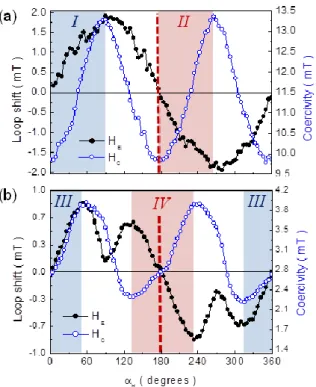
Fig. 5. Angular evolution of the loop shift (close symbols) and coercivity (open) vs field angle, H, for SmCo5(30nm)/spacer/CoFeB(3nm) with a thickness of the spacer (a) 4.3 nm and (b) 12.8 nm. Shaded regions illustrate regions I-II and III-IV indicated in Figs. 3a,b, respectively. Angle H = 0° corresponds to application of the external field parallel to the easy axis direction of the Si/SiO2/CoFeB reference sample. Dash line is a visual guide indicative of H = 180°.
sample with the thinnest and the thickest spacer (Figs. 5a,b). Independently of the thickness of the spacer layer, the loop shift has 360° symmetry while coercivity has 180° symmetry, which is the well-known result of the unidirectional nature of the exchange bias phenomenon.33,42 However, with increasing the thickness of the spacer, the magnetostatic coupling between the CoFeB and the SmCo5 layers is diminished and, accordingly, the uniaxial anisotropy of CoFeB begins to play a relevant role as it may be observed by the presence of two maxima(minima) in the angular region H = 0-180° (H = 180-360°). As a consequence, the cosine angular dependence of the bias field,42 related to the unidirectional anisotropy, typically observed in EB systems, becomes frustrated by an increased influence of the uniaxial anisotropy of the CoFeB layer (Fig. 5b).
3.5 Chiral exchange-bias phenomenon
An additional multilayer structure was grown in the same fashion as detailed for the previous two samples to proof that a bias field can be induced in an orthogonally coupled SmCo5 (out-of-plane)/spacer/CoFeB(in-plane) system independently of using a material different to Chrome (Cr) as constituent of the spacer. With this aim a sample with a spacer comprising Tantalum (Ta) instead of Cr was grown, specifically with the following structure: Al2O3(0001)/Ru(20nm)/SmCo5(30nm)/Ta(3nm)/Pt(1.8nm)/CoFeB(3n m-oblique)/Pt(1.8nm). Fig. 6a shows a room temperature MOKE hysteresis loop measured with the external in-plane magnetic field applied along H = 90°, where a shift of the hysteresis loop towards
Fig. 6. In-plane hysteresis loops measured by MOKE for Al2O3(0001)/Ru/SmCo5(30nm)/Ta(3nm)/Pt(1.8nm)/CoFeB(3nm)/Pt(1.8nm) after application of an out-of-plane magnetic field of 2 T upwards (a) and downwards (b), respectively. A symmetric break of ±2 mT has been introduced in the field axis to allow for a better comparison. Images illustrate schematic representation of the multilayer structure and the two different orientations of the magnetization in the SmCo5 layer.
negative field values is clearly distinguishable. Consequently, and independently of using Cr or Ta, a bias field is induced in this orthogonally coupled system. In a second step, and in order to proof the control that the orientation of the magnetization of the SmCo5 layer exerts on the EB-like effect phenomenon, we decided to switch the magnetization orientation in the SmCo5 layer from upwards to downwards by application of an external magnetic field of 2 T perpendicular to the film surface as schematically illustrated in Figs. 6a,b, respectively. The effect of switching the magnetization state in SmCo5 (from upwards to downwards) on the sign of the bias field (from negative to positive) is straightforward as observed from a direct comparison of the recorded hysteresis loops (H = 90°) shown in Fig. 6. Coercive and bias fields take the same values in both situations, respectively, although the sign of the bias field is reversed when magnetizing the SmCo5 layer in opposite sense. This result points to the main role played by the dipolar field created by the SmCo5 layer in defining the initial sign of the bias field in the SmCo5-CoFeB system.
Conclusions
In summary, exceptional exchange bias-like effects have been observed in a system consisting of a hard magnet epitaxial SmCo5 film with out-of-plane anisotropy in interaction with a soft magnetic amorphous CoFeB film with in-plane anisotropy through a spacer. By contrast with conventional EB films, this system shows extraordinary features induced by application of an external
ARTICLE Nanoscale
8 | J. Name., 2012, 00, 1-3 This journal is © The Royal Society of Chemistry 20xx
magnetic field and, by contrast with typical EB systems, with no need of any post-growth annealing treatment:
(i) Possibility of tuning not only the magnitude, but also the sign of the bias field (with no need of any post-annealing treatment). This is achieved in a manner not reported to date for any exchange bias system: pinning exclusively one of the hysteresis loop branches (either the ascending or the descending branch) while simultaneously displacing the second branch along the field axis. As a consequence the bias field can be modulated from negative to positive values going through zero (i.e., no bias). This mechanism is reversible and the choice of the pinned branch is done by selecting the orientation of an external magnetic field applied parallel to the film surface.
(ii) Possibility of frustrating the cosine angular dependence of the bias field by modifying the magnetostatic coupling strength through variation of the thickness of a spacer between the CoFeB (in-plane) and the SmCo5 (out-of-plane) layers.
(iii) Chiral exchange-bias phenomenon: switching the orientation of the magnetization (upwards/downwards) in the SmCo5 film allows for fixing the initial sign of the bias field in the SmCo5/spacer/CoFeB system.
A systematic study done by changing the magnetization states of both hard and soft magnetic layers has confirmed that the observed effects are due to the interplay between the uniaxial anisotropy of the soft magnetic layer and the bias field imprinted in the soft layer by the magnetostatic field provided by the hard layer. We have proven that the combination of the uniaxial anisotropy induced in the CoFeB layer and the dipolar field created by the out-of-plane magnetized SmCo5 layer is mandatory to guarantee the appearance of this novel phenomenon. Variation of the thickness of the CoFeB layer might be an additional factor to modulate the bias field reported in this study. The observed effect is of interest for applications in the development of magnetic read-heads and magnetic sensors as it allows for a controlled modulation of both the bias field strength and the sign in a manner not reported to date, thus opening the path to a new generation of spintronic devices.
Conflicts of interest
There are no conflicts to declare.
Acknowledgements
This research was supported by the Joint German-Spanish Actions Programme (DAAD and Fundación Universidad.es via Ref. 57050243), the Spanish Ministerio de Economía y Competitividad (MINECO) through “SIESPER” (MAT2011-25598) Project, and the Regional Government of Madrid through NANOMAGCOST (P2018/NMT-4321) project. D.S. acknowledges financial support from Xunta de Galicia under the postdoctoral program I2C Plan (Modalidade B). IMDEA
Nanoscience is supported by the ‘Severo Ochoa’ Programme for Centres of Excellence in R&D, MINECO [grant number SEV-2016-0686].
References
1 O. Gutfleisch, M. A. Willard, E. Brück, C. H. Chen, S. G. Sankar and J. P. Liu, Adv. Mater., 2011, 23, 821.
2 W.H. Meiklejohn and C. P. Bean, Phys. Rev., 1956, 102, 1413. 3 P. K. Manna and S. M. Yusuf, Phys. Rep., 2014, 535, 61.
4 M.-H. Phan, J. Alonso, H. Khurshid, P. Lampen-Kelley, S. Chandra, K.S. Repa, Z. Nemati, R. Das, O. Iglesias, and H. Srikanth,
Nanomaterials, 2016, 6, 221.
5 J. Nogués and I.K. Schuller, J. Magn. Magn. Mater., 1999, 192, 203.
6 J. Camarero, J. Sort, A. Hoffmann, J.M. García-Martín, B. Dieny, R. Miranda and J. Nogués, Phys. Rev. Lett., 2005, 95, 057204. 7 S. H. Chung, A. Hoffmann and M. Grimsditch, Phys. Rev. B, 2005,
71, 214430.
8 J. Nogués, D. Lederman, T.J. Moran and Ivan K. Schuller, Phys. Rev.
Lett., 1996, 76, 4624.
9 P. Miltényi, M. Gierlings, M. Bamming, U. May, G. Güntherodt, J. Nogués, M. Gruyters, C. Leighton and Ivan K. Schuller, Appl. Phys.
Lett., 1999, 75, 2304.
10 N.J Gökemeijer and C.L. Chien, J. Appl. Phys., 1999, 85, 5516. 11 A. Migliorini, B. Kuerbanjiang, T. Huminiuc, D. Kepaptsoglou, M.
Muñoz, J.L.F. Cuñado, J. Camarero, C. Aroca, G. Vallejo-Fernández, V.K. Lazarov and J.L. Prieto, Nat. Mater., 2018, 17, 28.
12 J. Sort, A. Popa, B. Rodmacq and B. Dieny, Phys. Rev. B, 2004, 70, 1744310.
13 A. Bollero, L.D. Buda-Prejbeanu, V. Baltz, J. Sort, B. Rodmacq and B. Dieny, Phys. Rev. B, 2006, 73, 144407.
14 A. Bollero, B. Dieny, J. Sort, K. S. Buchanan, S. Landis and J. Nogués, Appl. Phys. Lett., 2008, 92, 022508.
15 W.C. Cain and M.H. Kryder, J. Appl. Phys., 1990, 67, 5722. 16 P. P. Freitas, J.L. Leal, L.V. Melo, N.J. Oliveira, L. Rodrigues and
A.T. Sousa, Appl. Phys. Lett., 1994, 65, 493.
17 D. Navas, J. Torrejon, F. Béron, C. Redondo, F. Batallan, B.P. Toperverg, A. Devishvili, B. Sierra, F. Castaño, K.R. Pirota and C.A. Ross, New J. Phys., 2012, 14, 113001.
18 T.N.A. Nguyen, Y. Fang, V. Fallahi, N. Benatmane, S.M. Mohseni, R.K. Dumas, and J. Åkerman, Appl. Phys. Lett., 2011, 98, 172502. 19 A. Bollero, V. Baltz, L.D. Buda-Prejbeanu, B. Rodmacq and B.
Dieny, Phys. Rev. B, 2011, 84, 094423.
20 H.P. Klein, A. Menth and R.S. Perkins, Physica A, 1975, 80B, 153. 21 R. Kütterer, H.-R. Hilzinger and H. Kronmüller, J. Magn. Magn.
Mater., 1977, 4, 1.
22 E.E. Fullerton, J.S. Jiang, Ch. Rehm, C.H. Sowers and S.D. Bader,
Appl. Phys. Lett., 1997, 71, 1579.
23 A. Singh, V. Neu, R. Tamm, K. Rao, S. Fähler, W. Skrotzki, L. Schultz and B. Holzapfel, J. Appl. Phys., 2006, 99, 08E917. 24 E.E. Fullerton, J.S. Jiang, C.H. Sowers, J.E. Pearson and S.D. Bader,
Appl. Phys. Lett., 1998, 72, 380.
25 Y. Liu, Y.Q. Wu, M.J. Kramer, Y. Choi, J.S. Jiang, Z.L. Wang and J.P. Liu, Appl. Phys. Lett., 2008, 93, 192502.
26 S. Sawatzki, R. Heller, Ch. Mickel, M. Seifert, L. Schultz and V. Neu, J. Appl. Phys., 2011, 109, 123922.
27 F. Magnus, M.E. Brooks-Bartlett, R. Moubah, R.A. Procter, G. Andersson, T.P.A. Hase, S.T. Banks and B. Hjörvarsson, Nat.
Commun., 2016, 7, 11931.
28 M. Seifert, V. Neu and L. Schultz, Appl. Phys. Lett., 2009, 94, 022501.
29 M. Seifert, I. Knittel, U. Hartmann, L. Schultz and V. Neu, J. Phys.
D: Appl. Phys., 2012, 45, 175001.
30 E.E. Fullerton, J.S. Jiang, M. Grimsditch, C.H. Sowers and S.D. Bader, Phys. Rev. B, 1998, 58, 12193.
31 K. Mibu, T. Nagahama and T. Shinjo, J. Magn. Magn. Mater., 1996, 163, 75.
32 T.J. Klemmer, K.A. Ellis, L.H. Chen, B. van Dover and S. Jin, J. Appl.
Phys., 2000, 87, 830.
33 J.L.F. Cuñado, A. Bollero, T. Pérez-Castañeda, P. Perna, F. Ajejas, F.J. Pedrosa, A. Gudín, A. Maldonado, M.A. Niño, R. Guerrero, D. Cabrera, F.J. Terán, R. Miranda and J. Camarero, Sci. Rep., 2017,
7, 13474.
34 A. Fernández-Pacheco, E. Vedmedenko, F. Ummelen, R. Mansell, D. Petit and R.P. Cowburn, Nat. Mater., 2019, 18, 679.
35 J. Sayama, K. Mizutani, T. Asahi and T. Osaka, Appl. Phys. Lett., 2004, 85, 5640.
36 S. Takei, A. Morisako and M. Matsumoto, J. Magn. Magn.
Mater., 2004, 272, 1703.
37 Y. K. Takahashi, T. Ohkubo and K. Hono, J. Appl. Phys., 2006, 100, 053913.
38 M. Ohtake, Y. Nukaga, F. Kirino and M. Futamoto, J. Appl. Phys., 2010, 107, 09A706.
39 J. Camarero, Y. Pennec, J. Vogel, M. Bonfim, S. Pizzini, F. Ernult, F. Fettar, F. Garcia, F. Lançon, L. Billard, B. Dieny, A. Tagliaferri and N.B. Brookes, Phys. Rev. Lett., 2003, 91, 027201.
40 J.C. Slonczewski, J. Magn. Magn. Mater., 1995, 150, 13.) 41 T.N. Anh Nguyen, Y. Fang, V. Fallahi, N. Benatmane, S.M.
Mohseni, R.K. Dumas and J. Åkerman, Appl. Phys. Lett., 2011,
98, 172502.
42 J. Nogués, J. Sort, V. Langlais, V. Skumryev, S. Suriñach, J.S. Muñoz and M.D. Baró, Phys. Rep., 2005, 422, 65.

![Fig. 2. Centered in-plane hysteresis loops measured by MOKE for CoFeB reference sample [Si/SiO 2 /Pt(1.8nm)/CoFeB(3nm)/Pt(1.8nm)] grown with oblique incidence (solid black line); Al 2 O 3 (0001)/Ru(20nm)/SmCo 5 (30nm)/](https://thumb-eu.123doks.com/thumbv2/123doknet/12912598.372611/5.892.459.827.698.967/centered-hysteresis-measured-cofeb-reference-sample-oblique-incidence.webp)