HAL Id: cea-02435061
https://hal-cea.archives-ouvertes.fr/cea-02435061
Submitted on 10 Jan 2020
HAL is a multi-disciplinary open access archive for the deposit and dissemination of sci-entific research documents, whether they are pub-lished or not. The documents may come from teaching and research institutions in France or abroad, or from public or private research centers.
L’archive ouverte pluridisciplinaire HAL, est destinée au dépôt et à la diffusion de documents scientifiques de niveau recherche, publiés ou non, émanant des établissements d’enseignement et de recherche français ou étrangers, des laboratoires publics ou privés.
rods in ASTRID
M. Zabiego, D. Lorenzo, T. Helfer, E. Guillemin
To cite this version:
M. Zabiego, D. Lorenzo, T. Helfer, E. Guillemin. Insertion reliability studies for the RBC-type control rods in ASTRID. International Conference on ast Reactors and Related Fuel Cycles ext Generation Nu-clear Systems for Sustainable Development(FR17), Jun 2017, Yekaterinburg, Russia. �cea-02435061�
INSERTION RELIABILITY STUDIES FOR THE RBC-TYPE
CONTROL RODS IN ASTRID
M. Zabiégo1, D. Lorenzo1, T. Helfer1, E. Guillemin2
1 CEA Cadarache, DEN, DEC, F-13108 Saint-Paul-lez-Durance, France 2
AREVA-NP, 10 rue J. Récamier, 69456 Lyon Cedex 06, France
E-mail contact of main author: [email protected]
Abstract. This paper reports on preliminary studies performed regarding the insertion reliability of the RBC-type Control Rods designed for the ASTRID Sodium-cooled Fast Reactor. At this stage, the primary aim of the analysis is to evaluate the mechanical behavior of RBC Control Rods under Emergency Shutdown conditions, for which reactor core structures are subjected to significant misalignments (including earthquake-imposed displacements). Using a Finite Element Model based on the Cast3M solver and developed specifically for these studies, computations are performed that allow assessing contact reactions (and the associated friction forces and contact pressures), deformations and stresses (mostly due to bending-induced deformations) which are considered for design. Based on these preliminary results, some optimization of the Control Rod design is proposed that ensures some stable behavior all along the rod drop, with substantial design margins.
Key Words: ASTRID, Control Rod, Insertion Reliability, Mechanical Behavior.
1. Introduction
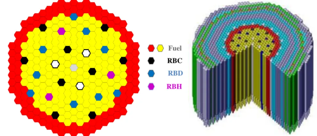
Safety is a key priority of CEA’s ASTRID (Advanced Sodium Technological Reactor for Industrial Demonstration) reactor project [1]. Reactivity control, which constitutes one of the critical issues in this respect, is ensured by various systems, used for power regulation, fuel depletion compensation and reactor shutdown (under both normal and emergency situations) [2]. To comply with the redundancy, diversity and independence requirements of the defense-in-depth approach considered for its design, ASTRID is planned to operate with three mobile absorber systems, respectively referred to as RBC, RBD and RBH [3][4]. Each system consists of a mobile drive mechanism housed in a static structure sleeve (bound to the above-core structure) and a mobile absorber rod housed in a static wrapper (bound to the below-above-core structure diagrid, itself bound to the above-core structure). The rod & wrapper pairs form the absorber subassemblies distributed in the core, as showed in Figure 1.
FIG. 1. ASTRID core configuration, featuring the RBC (black), RBD (blue) & RBH (magenta), as well as the fuel (yellow & red) and dummy (white & grey) subassemblies
| PAGE 1 Fuel
RBD
RBC
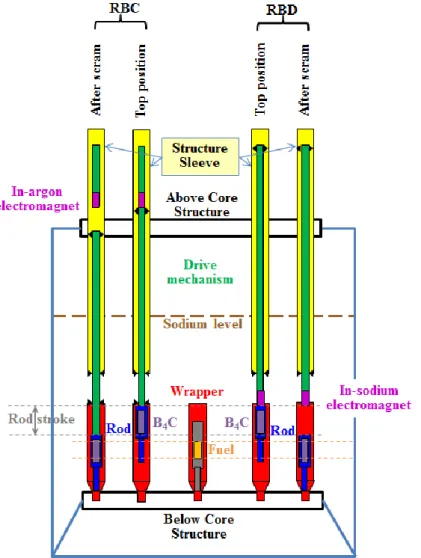
As illustrated in Figure 2, the RBC, which is the system of interest for the present paper, notably differs from the other 2 systems in that it maintains, under all (power on) operating conditions, a connection between the absorber rod and (at least part of) the drive mechanism: this connection is ensured by some mechanical gripper that grabs the head of the rod, or releases it during handling operations when it is parked at its bottom position.
FIG. 2. Absorber-Rod / Driven-Mechanism connection differences between RBC and RBD This feature implies that, as regards scram situations, the RBC, contrary to the other 2 systems, is susceptible to mechanical coupling between the above-core structure and the core. On the opposite, both the RBD and the RBH are characterized by having their absorber rod decoupled from static structures during scram phases, and thus mostly free to insert within the wrapper, with virtually no risk of significantly delaying (or even of blocking) the absorber insertion, even within a severely deformed reactor structures: the RBD, in particular, is designed to guarantee shutdown beyond category 4 situations (severe accidents).
As such, and as previously noted for the similar Superphenix SCP system [5], the RBC is the shutdown system for which insertion reliability is the most critical to ensure. This is particularly true under seismic situations, when displacements imposed to the mobile part of the system (control rod & drive mechanism), as the result of reactor/core structure misalignments, have the highest probability (albeit minimized by design) of preventing absorber insertion, owing to increased contact reaction forces between the mobile part, on the one hand, and the wrapper and the structure sleeve, on the other hand, as showed in Figure 3.
FIG. 3. Reinforced contact reactions under deformed-core conditions
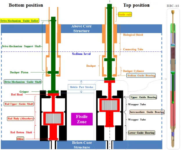
Nominal contact zones, between the mobile part of the system and the static structures in which it inserts, are specifically designed to ensure guiding functions at various levels. These are identified in Figure 4, which illustrates the reference configuration of the RBC system, featuring both the subassembly (RBC-AS) and the drive mechanism (RBC-BK). Nominal contact zones are protected by some hard coating aimed at preventing premature wear, so as to maximize component lifetime. Parasitic contact zones must be prevented by design: by ensuring proper clearance between mobile and static components, for instance.
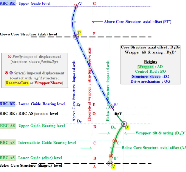
The boundary conditions, expressed in terms of the maximum displacements potentially imposed to the mobile part of the RBC through nominal contacts with the reactor & core structures, are further illustrated in Figure 5. One can separate the static contribution from the seismic contribution. The latter, based upon a “Safe Shutdown Earthquake” magnitude, is quite significant, despite the presence of earthquake dampers that filter out some of the seismic load.
FIG. 5. RBC boundary conditions, in terms of the displacements imposed to the mobile part
Contacts induce reaction forces, which lead to several potential consequences.
As the result of friction, normal forces associated with these contacts (when applied to the mobile part of the RBC during a shutdown phase, in particular), lead to tangential forces that oppose the gravitational drop of the absorber rod. Proper dimensioning must be performed to guarantee that these adverse forces have no detrimental effect on the absorber insertion kinetics.
The imposed displacements inducing the contacts lead to structural deformations: primarily, the slender beam-like mobile part (typically, the height is in excess of
10 meters, while the width varies from 3 centimeters to less than 20 centimeters) is subjected to bending, which requires dimensioning relative to bending stress.
Contact pressure (which can be estimated through Hertz formulae, for instance) must be carefully controlled, in order to verify that premature wear does not lead to early discharge of the RBC: the targeted lifetime is 4 irradiation cycles for subassemblies and 22 irradiation cycles for drive mechanisms.
The RBC design for ASTRID is derived from the operational experience gained from similar systems implemented in both the Phenix and Superphenix reactors (and designed for the EFR project), which were improved over about 30 years.
As regards the drive mechanism, insertion reliability issues are not significantly different from those of the past. The mobile part is guided at its top end (rollers guided in rails) and its bottom end (shaft guided in a bearing immersed in sodium).The bottom part of the structure sleeve is designed with some increased flexibility, and its housing of a dashpot implies some reduced clearance during the final phase of the rod drop.
The subassembly design required more investigations. Indeed, the reference design of ASTRID’s RBC-AS originally combined features from Phenix and Superphenix, from which it was necessary to identify optimizations. The RBC-AS involves 3 guide levels (Figure 4).
Upper guide level: cylindrical upper guide shaft (whose height covers the rod stroke) guided in cylindrical upper guide bearing (at the bottom of the subassembly head). A similar design was implemented in the Superphenix SCP, except for 2 differences.
The guide shaft was tubular with a large section in Superphenix, while it is solid with a small section (initially, 3 centimeters) in ASTRID.
The guide bearing had some hydraulic regulation function (that imposed a reduced clearance between the shaft and the bearing) in Superphenix, while there is no such constraint in ASTRID.
Intermediate guide level: cylindrical rod body (housing the absorber elements, over a height covering the rod stroke) guided by a 3-plane (positioned at 120°) guide bearing. A similar design was implemented in both Phenix and Superphenix.
Lower guide level: olive-shaped structure (at the bottom of the absorber rod) guided in a cylindrical guide bearing (over a height covering the rod stroke). A similar design was implemented in the Phenix “Barre de Commande”, albeit with a fixed guide level (located slightly below the Fissile Zone, which led to rod blockage as the result of swelling phenomena, during some rod withdrawal phases, with consequences on reactor operation but not on safety), while the guide level (olive) is mobile for ASTRID, and thus less susceptible to swelling issues, since it is kept further away from the source of irradiation during operational phases (the control rod is gradually
withdrawn from the core, as the irradiation cycle progresses, with a stroke of
350 mm, so that the position of the lower guide zone is kept between 550 mm and
200 mm below the bottom of the fissile zone). 2. Computational model
The RBC insertion reliability is analyzed, throughout the rest of this paper, by means of a computational procedure developed as a Finite Element Model based on the Cast3M solver, within the frame of linear elasticity. At this stage, the aim is not to investigate the insertion
kinetics. The analysis is conducted by considering successive static states, with the mobile part of the RBC positioned at a fixed altitude (successive positions along the control rod’s stroke of 1000 mm), and subjected to displacements imposed by the above/below core structure (see offset AA’ & FF’ in Figure 5) and the core (neighboring subassemblies, forming a compact structure subjected to collective displacements, impose some offset at the upper guide level of the RBC-AS: see DAD’ in Figure 5). Dynamic and hydraulic aspects are dealt with in a separate study.
The Finite Element Model considers beam elements, for meshing the mobile part of the RBC, as an axial stacking of cylindrical sections characterized by their geometry (height and inner/outer diameter) and material (associated properties, function of the specified axial temperature profile). The static parts (wrapper & structure sleeve) are modeled as rigid boundary conditions imposed to the mobile part: they are specified as axially stacked cylindrical sections (parametrized by their height and inner diameter). The contact zone at the bottom of the RBC-BK (point E’, in Figure 5) is dealt with in a specific way, because the structure sleeve cannot be considered as infinitely rigid (its stiffness is larger, but not infinitely larger, than that of the mobile part: ratio 25/1).
The Cast3M procedure automatically identifies the contact zones where mechanical interactions between the mobile and static parts occur, and then computes
The axial profile of the deformed mobile part;
The reaction force at the contact points;
The axial profile of the bending stress along the mobile part (to compare with admissible stress criteria);
The friction force at the contact points (derived from reaction forces, given an hypothesis on the friction coefficient: assumed 0.6, based on the operational feedback from Phenix and Superphenix, for in-sodium stainless-steel components, which is presently being tested for confirmation in dedicated sodium loops);
The contact pressure at the contact points (based on Hertz formulae [6]). 3. Results
In this section, we analyze the results successively obtained for
The original design, with 3 guide levels in the RBC-AS and reduced clearance between the mobile and the static parts at these levels (a radial gap of 1 mm is considered), as well as a slender upper guide shaft (a diameter of 30 mm is considered);
Some optimized design, with only 2 guide levels in the RBC-AS (the intermediate guide bearing is suppressed) and some larger clearance at the upper guide level (a radial gap of 5 mm is considered), as well as a reinforced upper guide shaft (a diameter of 40 mm is considered).
The results are analyzed with the contribution of seismic loads to the imposed displacements: the case when seismic loads are ignored is, of course, less critical for dimensioning.
3.1 Original design
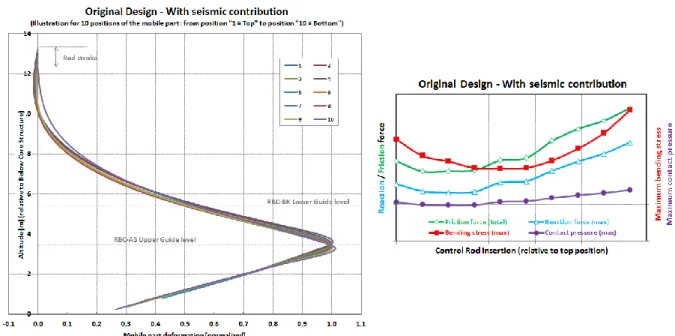
FIG. 6. Quantitative results obtained for the original (not optimized) design
The left figure highlights the fact that the mobile-part deformation is primarily accommodated at the upper guide level of the RBC-AS. This is made possible by
The choice of a slender upper guide shaft (solid section, with 30 mm diameter for a
1000 mm height) that offers some significant bending capability;
The low stiffness of the drive mechanism (for the part suspended underneath the above core structure).
The right figure illustrates the non-monotonic evolution of the mechanical behavior as the control rod insertion progresses, from the top position to the bottom position. Considering this evolution, from the left towards the right of the figure, one observes
Some initial improvement (when the control rod starts to insert) that particularly shows through the reduction of the maximum bending stress (measured at the upper guide level of the RBC-AS). This improvement is due to the fact that, as the control rod is inserted from its top position, the contact between the upper guide shaft and the upper guide bearing of the RBC-AS moves towards the middle of the former, and thus away from the stiffer section attached to the massive gripper, thus benefiting from some increased flexibility.
Some degradation, over the second half of the stroke, that shows on all four illustrated quantities. This is both a “mirror effect” of the improvement observed over the first half of the stroke, and the consequence of the contact that progressively develops at the intermediate guide level of the RBC-AS (there are contacts at the other 4 guide levels –upper and lower, for both the RBC-AS and the RBC-BK– all along the stroke). Some parasitic contact, between the drive mechanism and its structure sleeve, is observed in the upper part of the RBC-BK (where deformations are on the negative side of the graph). In addition, although calculated values in the right figure all reasonably comply with design criteria (which we do not review in this paper), it appears that this design is not optimized relative to the latter. For this reason, a number of alternative designs were studied, by way of parametric analyses: the optimized design eventually selected as the new reference design is discussed in the next section.
3.2 Optimized design
The optimized design is characterized by the following evolutions, which essentially affect the RBC-AS.
The intermediate guide level is suppressed: it is shown that it only added extra interaction, without any benefit in terms of preventing parasitic contacts (despite the suppression of the intermediate guide bearing, the rod body does not exhibit any parasitic interaction with the hexagonal duct of the wrapper).
The upper guide shaft diameter is increased from 30 mm to 40 mm, and the upper guide bearing inner diameter is increased from 32 mm to 50 mm.
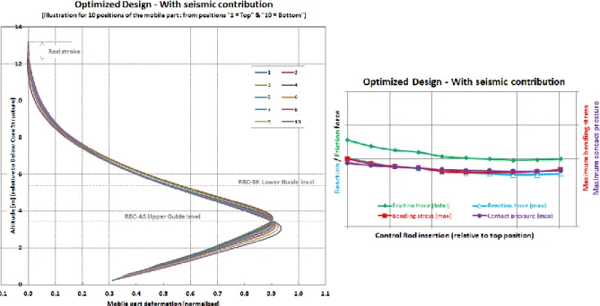
The results obtained for the optimized (new reference) design are illustrated in Figure 7.
FIG. 7. Quantitative results obtained for the optimized design (same scale as Figure 6)
The left figure highlights the fact that the axial profile of the mobile-part deformation is smoother than it was for the original design. In particular, the negative deformation previously observed in the upper part of the RBC-BK has been corrected, so that there is no parasitic contact between the drive mechanism and its structure sleeve, anymore. This is essentially due to the increase in the diameter of the upper guide shaft that reinforces the stiffness of the mobile part, so as to prevent excessive deformations. The opening of the upper guide gap (from 1 mm to 5 mm, radially) also allows reducing the amplitude of the imposed deformation at this level. Opening the gap even more could be beneficial, but this would increase the risk of an impact between the control rod’s head and the wrapper’s head, which must be excluded because it would occur before the mobile-part’s velocity is sufficiently reduced by the dashpot implemented at the bottom of the RBC-BK.
The right figure illustrates the stability of the mechanical behavior as the control rod insertion progresses, from the top position to the bottom position. All four represented quantities exhibit only little variations and continuous improvement (i.e., reduction) all along the stroke. The reaction and friction forces, as well as the bending stress, are significantly reduced, compared to their values in the original design. Contact pressure is the only quantity whose
magnitude increases relative to the original design: this results from the fact that the maximum value is associated with the upper guide level of the RBC-AS, for which the mismatch in the inner/outer diameters has been increased (contact pressure is proportional to the square root of the diameter difference, according to Hertz formulae).
4. Conclusions & perspectives
The present study was dedicated to optimizing the design for the RBC system of ASTRID, relative to control rod insertion reliability, considering only the static mechanical behavior. Several geometrical evolutions of the RBC-AS guide levels have been proposed.
The most significant is the suppression of the intermediate guide level. It leads to important design/manufacturing simplifications, as it eliminates a complex component of the wrapper that previously joined two separate sections of its hexagonal duct (now a unique piece). In addition, it constitutes some safety improvement, in the sense that the intermediate guide level of the RBC-AS was, among all guide levels, the one exposed to the highest neutronic flux, which thus implied careful control of the associated clearance evolution under irradiation. The lower guide level is conserved, but mostly for hydraulic motives: it has been shown that its mechanical role is limited, but it remains essential as regards channeling the coolant flow towards the bundle of absorber pins with minimum bypass.
The quantitative results obtained through this study reinforce the confidence in the RBC system, relative to its ability to ensure safe shutdown of the reactor core under all design basis conditions.
Although insertion kinetics has not been modeled at this stage, the finding that the cumulated friction forces (associated with interactions between static and mobile components) amount to less than one third of the mobile-part’s weight, under the most penalizing conditions (maximum seismic load), provides some significant margin.
As regards the mechanical resistance of critical components, significant design margins are also identified: the RBC-AS upper guide shaft, which accommodates most of the bending load of the design, exhibits a margin of 4 in terms of the bending stress it is subjected to, relative to the limit dictated by design criteria.
Complementary to this study, further analyses are planned or already in progress.
Analytical tribology tests are in progress, to consolidate the present friction coefficient hypotheses; and they will be complemented by some integral tests to be performed at the component scale, rather than on material samples.
Complementary computational studies are planned, to both account for dynamic (seismic) and hydraulic (fluid/structure interactions) loads, as well as to perform focus analyses, based on 3D Finite Element Modeling, on selected sections of the RBC for which beam theory is known to be potentially inaccurate.
Mechanical tests, at the scale of the system, are being discussed: they will constitute the ultimate proof of the insertion reliability for the optimized design.
ACKNOWLEDGEMENTS
The authors are grateful to M. Occelli, who participated in the initial development of this work, through the development of the Cast3M script used for computations, during his internship.
REFERENCES
[1] CEA – Nuclear Energy Division, 4th-Generation Sodium-Cooled Fast Reactors – The ASTRID Technological Demonstrator (December 2012)
http://www.cea.fr/english/Documents/corporate-publications/4th-generation-sodium-cooled-fast-reactors.pdf
[2] I. GUÉNOT-DELAHAIE, D. LORENZO, B. VALENTIN, J.M. ESCLEINE, T. HELFER, “State of the art of the conceptual designs for ASTRID control and shutdown rods”, Proc. of the FR13 Conference (Paris, France, 2013), Paper IAEA-CN-199-285. [3] B. FONTAINE, P. SCIORA, M. VANIER, C. VENARD, “ASTRID : an innovative
control rod system to manage reactivity”, in Proc. of the ICAPP’16 Conference (San Francisco, USA, April 17-20, 2016)
[4] I. GUÉNOT-DELAHAIE, D. LORENZO, B. VALENTIN, M. ZABIÉGO, V. SOUKPHOUANGKHAM, F. BISCARRAT, T. LAMBERT, M. PHÉLIP, “The Innovative RBH Complementary Safety Device For ASTRID To Address Unprotected Loss Of Flow Transients: From Design to Qualification”, in Proc. of the ICAPP’16 Conference (San Francisco, USA, April 17-20, 2016)
[5] D. BROCHARD, P. BULAND, “Seismic qualification of SPX1 shutdown systems – Test and calculations”, in Specialists' meeting on fast breeder reactor-block antiseismic design and verification (Bologna, Italy, 12-15 October, 1987) – IAEA report IWGFR-65 (1988)
https://inis.iaea.org/search/search.aspx?orig_q=RN:21083861