HAL Id: in2p3-00862378
http://hal.in2p3.fr/in2p3-00862378
Submitted on 11 Mar 2014HAL is a multi-disciplinary open access archive for the deposit and dissemination of sci-entific research documents, whether they are pub-lished or not. The documents may come from teaching and research institutions in France or abroad, or from public or private research centers.
L’archive ouverte pluridisciplinaire HAL, est destinée au dépôt et à la diffusion de documents scientifiques de niveau recherche, publiés ou non, émanant des établissements d’enseignement et de recherche français ou étrangers, des laboratoires publics ou privés.
Measurement and Control of the Beam Intensity for the
SPIRAL2 Accelerator
S. Leloir, T. André, B. Ducoudret, C. Jamet, G. Ledu, C. Potier de Courcy
To cite this version:
S. Leloir, T. André, B. Ducoudret, C. Jamet, G. Ledu, et al.. Measurement and Control of the Beam Intensity for the SPIRAL2 Accelerator. 2nd International Beam Instrumentation Conference -IBIC2013, Sep 2013, Oxford, United Kingdom. pp.900-902, 2013. �in2p3-00862378�
MEASUREMENT AND CONTROL OF THE BEAM INTENSITY
FOR THE SPIRAL2 ACCELERATOR
S. Leloir
#, T. André, B. Ducoudret, C. Jamet, G. Ledu, C. Potier de Courcy,
GANIL, Caen, France
Abstract
The phase 1 of the SPIRAL2 facility is under construction at the national heavy ion accelerator (GANIL, Caen, France). The accelerator including an RFQ and a superconducting LINAC will produce deuteron, proton and heavy ion beams in a wide range of intensities and energies (beam power range: a few 100W to 200kW). The measurements of the beam intensities are ensured by means of several AC and DC Current Transformers (ACCT/DCCT).
These measurements are required for the accelerator tuning and the beam controls for safety requests during the daily operation. The uncertainty has to be taken into account to determine the threshold values. This paper presents the measuring chain description of ACCT/DCCT, the signal processing by integration and the uncertainty studies.
ACCELERATOR CHARACTERISTICS
SPIRAL2 will produce different beams (protons, deuterons and heavy ions) at very high intensity. Table 1 recalls the main beam characteristics.
Table 1: Beam Specifications
Beam P D+ Ions
Max. Intensity 5mA 5mA 1mA
Max. Energy 33MeV 20MeV/A 14.5MeV/A Max. Power 165kW 200kW 48kW
The beam will be chopped so as to reduce the mean intensity while keeping the same peak current. The chopper is necessary in the tuning phases of accelerator in order to increase the beam power progressively.
The duty cycle of the slow chopper ranges are: from 1/10000 to 1/2000 at 1Hz
from 1/2000 to 1/1 at 5Hz
NON DESTRUCTIVE BEAM INTENSITY
MEASUREMENTS
In order to control continuously the intensities and the losses, non-destructive beam intensity measurements are set up along the accelerator [1]:
at the entrance of the Radio Frequency Quadrupole (RFQ)
at the entrance and the exit of the LINAC at the Beam Dump entrance
RFQ LINAC Deuteron Proton source Ion Source Beam Dump NFS Experimental Area S3 Experimental Area Future Production Building
DCCT ACCT/DCCT ACCT/DCCT ACCT/DCCT
Figure 1: Intensity measurement locations. The use of two kinds of non destructive measurement chains DCCT (Bergoz NPCT-175-C030-HR) and homemade ACCT is justified by the difference of detection principles and by their complementarities.
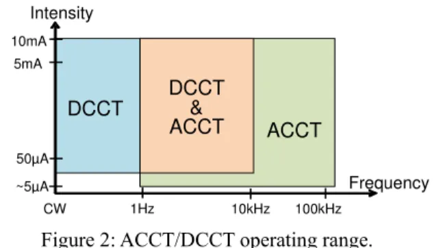
DCCT Intensity 50µA 5mA CW Frequency ~5µA DCCT & ACCT ACCT 100kHz 1Hz 10kHz 10mA
Figure 2: ACCT/DCCT operating range.
The DCCTs measure the intensity of continuous and chopped beams with a slow response time (about 50 µs for a bandwidth of 10 kHz). The minimum intensity that can be measured is few 10µA due to the offset level.
The ACCTs are faster with rise times about 1µs and with minimum levels less than 10µA.
The measurements of intensities and transmissions are required for the accelerator tuning (command-control) and the beam controls for safety (Machine Protection System: MPS). The difference of the measured intensities gives the transmission of the MEBT, Linac and HEBT lines. Threshold Monitoring Bergoz NPCT Electronics MPS Command Control ACCT/DCCT bloc 10V/10mA Ganil ACCT Electronics Alarms 10V/10mA
Figure 3: Setup of an ACCT/DCCT chain.
___________________________________________
#leloir@ganil.fr
WEPF33 Proceedings of IBIC2013, Oxford, UK
ISBN 978-3-95450-127-4 Copyright c○ 2013 by J A C oW — cc Cr eati v e Commons Attrib ution 3.0 (CC-BY -3.0)
BEAM CONTROLS
The intensity controls are part of the Machine Protection System (MPS) [2] which ensures the control and the protection of the accelerator. The MPS is divided into two subsystems:
The thermal protection system protects the accelerator against direct beam thermal damage.
The enlarged protection system controls: the facility operating range
the radiation produced by beam losses the integrity of beam dump and targets
The MPS receives alarm signals from several diagnostics. Depending on the accelerator mode, when an alarm is active, the MPS system triggers a beam cut.
ALARM SIGNALS
The mean intensities and losses are compared to maximum allowed intensities i.e. thresholds. Each threshold overrun generates an alarm.
The slow chopper periods (1s or 200ms) and the required response time (<1s) do not enable to use a simple filter to extract the mean intensity.
A digital moving integration over 1s or 200ms allows: response times lower than slow chopper period response times depending on intensity level excess
0 1 2 3 4 5 6 0 50 100 150 200 250 300 350 400 450 500 550 600 650 700 750 800 0 50 100 150 200 250 300 350 400 450 500 550 600 650 700 750 800 Alarm Threshold Moving integration over 200ms Beam Intensity Overrun Time(ms) Time(ms) 0,75 2,25
Figure 4: Threshold monitoring by moving integration.
Integrator P rinciple
The ACCT or DCCT signal is converted into a pulse frequency. Continually, a counter adds up the pulses and removes the delayed pulses. The delay corresponds to the time interval of integration. This time is equal to a multiple of the chopper period, the counter value is then representative of the input average signal.
Delay Voltage to Frequency Converter Pulse Counter UP DOWN Pulses DCCT or ACCT signal Delayed pulses Pulses Digital signal average
Figure 5: Integrator principle.
Electronic M onitoring
To generate the alarm signal, the counter starts at the threshold value and its inputs are inverted (count down the pulses and count up the delayed pulses). Therefore, the counter value is equal to the threshold value minus the integrator value.
A negative value of counter is equivalent to the exceeded threshold. In that case, the alarm signal is the sign bit of the counter.
Delay Voltage to Frequency Converter Pulse Counter DOWN UP Pulses 2MHz/10mA DCCT or ACCT signal 10V/10mA Threshold Interface Threshold digital value Exceeded threshold information Alarm signal
Figure 6: Synoptic of threshold monitoring.
A microcontroller is added to this architecture. It can also perform the counting function and monitor the other thresholds with less reliability but more flexibility. The microcontroller manages the other functions like the communication between the electronics and the command control.
UNCERTAINTY IN MEASUREMENT
The threshold values must take into account the measurement uncertainty [3]. The influence quantities in the total uncertainty are:
Offset Noise
External Electromagnetic field Linearity and accuracy of the gain Temperature drifts (only DCCT) Low drop (only ACCT)
Slew rate
Time lag between two chains (only efficiency transmission measurement by ACCT)
Tests and measurements were realized to study the standard measurement uncertainties. A test bench was developed to characterize the ACCT and DCCT chains.
Test B ench
The bench principle is to put ACCT/DCCT under real operating conditions. The beam is simulated by a current in a test spire through the ACCT/DCCT blocs. This current is modulated by a function generator and a current chopper. The output voltages of diagnostics are monitored by a voltmeter synchronized on the function generator. A computer drives the current generator and the voltmeter for automatic characterizations of the ACCT/DCCT.
Proceedings of IBIC2013, Oxford, UK WEPF33
Beam Charge Monitors and General Diagnostics
ISBN 978-3-95450-127-4 901 Copyright c○ 2013 by J A C oW — cc Cr eati v e Commons Attrib ution 3.0 (CC-BY -3.0)
Multimeter (voltmeter) Keithley2701 Synchro Function generator Agilent33521A Chopper Modulation Output Peak current Current generator Keithley263 Spire test DCCT electronics Computer (Labview) Intensity level Acquisition (Ethernet) DCCT1 ACCT1 DCCT2 ACCT2 DCCT3 ACCT3 ACCT electronics Current Time De v ic e u n d e r t e s t
Figure 7: Bench setup.
The linearity and the offset drift versus the room temperature have been quantified with this bench.
Optimization of ACCT Low Drop
The low drop is the gradual fall of the ACCT signal during a constant pulse beam. The low drop uncertainty is proportional to the pulse duration. A new electronic was developed to reduce the ACCT low frequency up to few 10mHz.
A clamp function is implemented to generate the DC of the ACCT signal. The negative component corresponding to the beam off is set to zero at each chopper period by a digital clamp. The low drop effect is minimized when the clamp is trigged in the middle of the time off.
Optimization of DCCT Offset
The DCCT offset arises mainly from the temperature of transformers. Under normal conditions, the room temperature varies between 15°C to 31°C. So, the offset can be superior to 100µA.
A study is in progress to stabilize the temperature of the ACCT/DCCT blocs.
Optimization of External Electromagnetic F ield
Three shielding layers (Armco, Mu-metal and copper) protect the sensors from external electromagnetic fields.
A vertical shield plate between AC and DC sensors is installed to minimize the disturbance produced by the DCCT magnetic modulator on the ACCT.
GANIL ACCT Bergoz DCCT Several layers of Magnetic shield Insulating gaps
Figure 8: ACCT/DCCT bloc section.
Statement of the U ncertainties
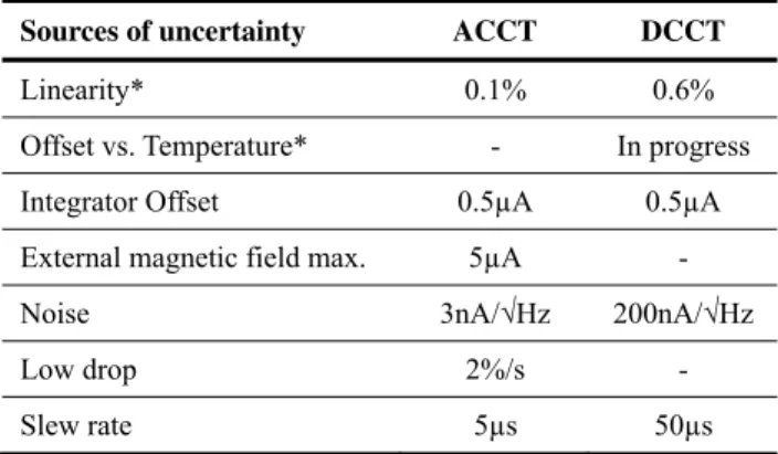
The next datasheet (Table 2) resumes the uncertainties for ACCT and DCCT.
Table 2: Statement of the Uncertainties
Sources of uncertainty ACCT DCCT
Linearity* 0.1% 0.6%
Offset vs. Temperature* - In progress Integrator Offset 0.5µA 0.5µA External magnetic field max. 5µA -
Noise 3nA/√Hz 200nA/√Hz
Low drop 2%/s -
Slew rate 5µs 50µs
*measured by the GANIL test bench
CONCLUSIONS
The ACCT/DCCT blocs are made and qualified. The Ganil electronics are in the prototype step. The monitoring threshold system and the DCCT temperature stabilization are being characterized.
The next step consists to measure the uncertainties of the global chain (diagnostic, electronic and integrator) with the Test Bench.
Another step is to improve the system after the Failure Mode and Effect Analysis (FMEA).
The last step will be the manufacturing of the final version of the electronic cards and the re-characterization.
REFERENCES
[1] C. Jamet et al., “Injector Diagnostics Overview of SPIRAL2 Accelerator”, DIPAC2007, Venice, Italy. [2] M-H. Moscatello et al., “Machine Protection System
for the SPIRAL2 Facility”, IPAC2012, New Orleans, Louisiana, USA.
[3] C. Jamet et al., “Beam Intensity and Energy Control for the SPIRAL2 Facility”, LINAC2012, Tel-Aviv, Israel.
WEPF33 Proceedings of IBIC2013, Oxford, UK
ISBN 978-3-95450-127-4 Copyright c○ 2013 by J A C oW — cc Cr eati v e Commons Attrib ution 3.0 (CC-BY -3.0)