CERAMIX MATRIX MICROCOMPOSITES PREPARED BY P-RCVD WITHIN THE (Ti-Si-B-C) SYSTEM
Sylvain JACQUES
LCTS, CNRS, University of Bordeaux 1, Herakles-Safran, CEA 3 allee de la Boetie, F-33600 Pessac, France
ABSTRACT
Nanoscale carbide multilayered interphases were deposited within the (Ti-Si-B-C) system by pressure-Pulsed Reactive Chemical Vapor Deposition (P-RCVD) on single filament Hi-Nicalon fibers and embedded in a SiC matrix sheath. The Reactive method, in which the titanium-containing layer growth involves the consumption of the pre-deposited Si-B-C sub-layer, allowed TiC- and TiB2
-based films to be obtained with a porous multilayer microstructure as a result of the Kirkendall effect. A first difficulty relied on the protection of the fiber surface which was very sensitive to chemical attack by P-RCVD. This difficulty could be circumvented through a first deposited SiC sub-layer thick enough to protect the surface of the fiber. But, because the porosity volume fraction was still not high enough, the role of mechanical fuse of these pyrocarbon-free interphases could not be evidenced from the microcomposite tensile curves, which remained fully linear up to the failure. Finally, the P-RCVD method was applied to the matrix processing itself. Microcomposites, this time with a pyrocarbon interphase but also with new matrix materials such as Ti3SiC2, were prepared and
characterized.
INTRODUCTION
In Ceramic Matrix Composites (CMCs) reinforced by continuous fibers, despite the brittleness of the ceramic, a good toughness can be achieved by adding between the fiber and the matrix a thin film of a compliant material called "interphase".1 Pyrocarbon (PyC) is the material commonly used
to play this role, but its poor oxidation resistance is responsible for the loss of strength of these composites when used at high temperature in oxidizing atmosphere.2 The use of interphases only
made of carbide and/or boride would allow CMC properties to be maintained in severe conditions. The problem of boro-carbide brittleness and the achievement of a mechanical fuse could be overcome by introducing porosity in the film as proposed by Carpenter et al.3 or by laminating the carbide
material itself at the nanometer scale.
A way to process nanoscale multilayered coatings is the use of pressure-Pulsed Chemical Vapor Deposition (P-CVD), a method adapted from CVD.4,5 Another way is the use of
pressure-Pulsed Reactive CVD (P-RCVD) adapted from the RCVD method in which a part of the elements of the deposited coating comes from the substrate.6
The first aim of the present contribution was to study new porous and multilayered PyC-free coatings obtained by P-RCVD from a H2/TiCl4 gaseous mixture not reacting with classical initial
pure PyC sub-layers but with SiC-PyC, i.e. SiC sub-layers containing PyC, or Si-B-C sub-layers similar to the ones studied by Pallier et al.7 The second aim was to take advantage of the possibilities
offered by the P-RCVD method to prepare and study pure Ti3SiC28 as a matrix material that could be
EXPERIMENTAL
The experimental study was carried out by using microcomposites. A microcomposite is a model composite consisting of one single fiber coated with the interphase and embedded in the matrix. It represents the elementary cell of the composite.10 The coatings were deposited on
Hi-Nicalon single fibers (~14 µm in diameter, from Nippon Carbon, Japan) by P-CVD and P-RCVD at a temperature close to 1373 K in the same CVD device as Jouanny et al.11 When used, the PyC
interphase with a thickness of ~100 nm was deposited by P-CVD from C3H8. SiC or Si-B-C
sub-layers were deposited by P-CVD from a H2/MTS or H2/BCl3/MTS gaseous mixture (MTS:
CH3Cl3Si). The TiC porous interphases were obtained by P-RCVD from SiC sub-layers in which
some PyC was added with on pulse of propane prior to total RCVD consumption. The number of H2/TiCl4 gas pulses was adjusted so to totally consume the previously deposited SiC-PyC sub-layers.
The carbon element of the initial SiC-PyC sub-layers is involved in the TiC growth whereas the silicon is evacuated in the gaseous phase in the form of by-product species. The multilayered coating deposited within the (Ti-Si-B-C) system was obtained from the partial consumption of the Si-B-C sub-layers by the H2/TiCl4 gas pulses. Finally, the Ti3SiC2 coatings were deposited by P-RCVD by
total consumption of previously deposited SiC sub-layers and with a higher dilution rate of TiCl4 in
H2 than in the case of the TiC growth as explained by Jacques et al.8 Each kind of microcomposite is
referred to as "fiber(f)/interphase/matrix(m)".
For the mechanical characterization, about fifteen microcomposites per batch were tensile tested in a monotonic way according to a single fiber test procedure.12 Before the tensile testing, the
diameter of each microcomposite was measured by a laser diffraction technique.13 The accuracy of
the diameter measurement was ± 0.5 µm. The stresses at failure were determined with an accuracy of ± 5 % by dividing the load at failure by the section of the specimen. For each batch of microcomposites, the given mechanical properties were arithmetic means. The microcomposites were observed by scanning electron microscopy (SEM) using backscattered electron (BSE) and secondary electron (SE) detectors. Chemical analyses of coatings were carried out by Auger electron spectroscopy (AES-VG Microlab 310F spectrometer) with simultaneous Ar+ etching in order to
obtain the concentration depth profiles of boron, carbon, titanium, oxygen and silicon. Coatings were also characterized by X-ray diffraction (XRD, Bruker D8, λCu-Kα1 = 0.154056 nm). In that case, the
coating was deposited on a graphite flat substrate placed in the CVD reactor in addition to the fibers.
RESULTS AND DISCUSSION
Microcomposites without PyC interphase TiC porous interphases
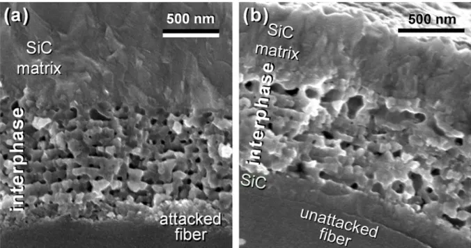
Figure 1.a shows a porous TiC interphase deposited directly on the Hi-Nicalon fiber with ten sequences of SiC-PyC-P-CVD/TiC-P-RCVD and then embedded in a 1.5 µm thick SiC matrix. The AES chemical analyses of such coatings (not shown here) only reveal the sole presence of titanium and carbon, silicon being not detected, which therefore confirms the total consumption of the SiC-PyC sub-layers. Although it is made of TiC only, the coating exhibits a multilayer-like microstructure, each TiC sub-layers having a thickness of about 100 nm. Lined up pores can be observed between the dense TiC sub-layers. These pores were produced by the Kirkendall effect based on nonreciprocal mutual solid-state diffusion process through an interface of two materials, i.e. carbon and silicon versus titanium atom diffusion between SiC and TiC. The roughness at the fiber surface shows that the fiber has been slightly attacked by the titanium containing species during the R-CVD process. The damaging of the fiber reinforcement led to an average tensile stress at failure of the SiC(f)/porousTiC/SiC(m) microcomposites of only 800 MPa (table 1) with a brittle behavior (figure
In order to avoid the fiber attack, a SiC sub-layer was first deposited by P-CVD at the fiber surface with a relatively large number of H2/MTS pulses. A large part of this SiC protective
sub-layer, about 150 nm, is still present at the fiber surface. Consequently the fiber was not attacked as evidenced by the smooth surface observed by SEM (figure 1.b). These last SiC(f)/SiC-porousTiC/SiC(m) microcomposites exhibit an average tensile stress at failure of 1070 MPa
(table 1). But despite the presence of porosity, no damageable behavior is observed in the tensile curves, which remain fully linear (figure 2.e). Therefore, the volume fraction of the porosity in this carbide interphase is still not high enough to deflect the matrix cracks according to the porous coating concept proposed by Carpenter et al..3
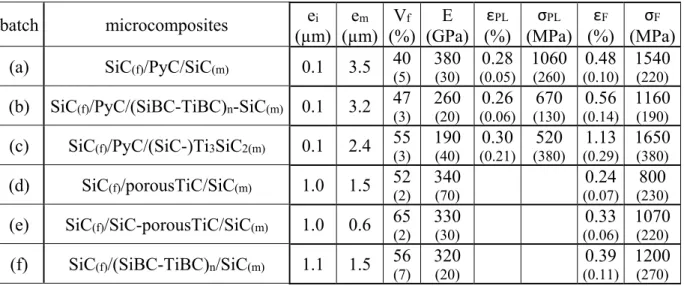
Table 1. Tensile mechanical characteristics of the microcomposites. ei and em are the thicknesses of the
interphase and the matrix. Vf is the fiber volume fraction. E is the Young’s modulus. εPL and σPL are the
proportional limit strain and stress, εF and σF are the strain and stress at failure. Standard deviations are given
in brackets. batch microcomposites ei (µm) em (µm) Vf (%) E (GPa) εPL (%) σPL (MPa) εF (%) σF (MPa) (a) SiC(f)/PyC/SiC(m) 0.1 3.5 40
(5) 380 (30) 0.28 (0.05) 1060 (260) 0.48 (0.10) 1540 (220)
(b) SiC(f)/PyC/(SiBC-TiBC)n-SiC(m) 0.1 3.2 47
(3) 260 (20) (0.06)0.26 (130)670 (0.14)0.56 1160 (190)
(c) SiC(f)/PyC/(SiC-)Ti3SiC2(m) 0.1 2.4 55 (3) 190 (40) 0.30 (0.21) 520 (380) 1.13 (0.29) 1650 (380) (d) SiC(f)/porousTiC/SiC(m) 1.0 1.5 52 (2) 340 (70) 0.24 (0.07) 800 (230)
(e) SiC(f)/SiC-porousTiC/SiC(m) 1.0 0.6 65 (2)
330
(30) (0.06)0.33
1070
(220)
(f) SiC(f)/(SiBC-TiBC)n/SiC(m) 1.1 1.5 56 (7) 320 (20) 0.39 (0.11) 1200 (270) (SiBC-TiBC)n interphase
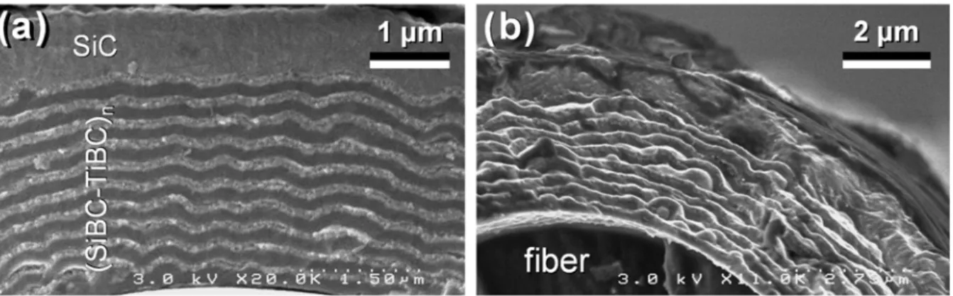
Figure 3 shows the fracture surface of microcomposites with (SiBC-TiBC)n interphase after
tensile test. On the BSE image (figure 3.a) the Si-B-C sub-layers appear in grey whereas the Ti-B-C sub-layers resulting from the attack of Si-B-C by H2/TiCl4 gas pulses appear in white because of the
presence of the heavier titanium element. High magnification observation shows that these ex-P-RCVD sub-layers are dual-layers separated by a row of pores in the middle. As the initial Si-B-C sub-layers were only partially consumed, the Hi-Nicalon fiber was not attacked. The average stress at failure of the SiC(f)/(SiBC-TiBC)n/SiC(m) microcomposites could be as high as 1200 MPa. Some
delamination in the multilayered interphase and between the interphase and the matrix can be observed on the fractures surfaces (figure 3.b) but no composite behavior is evidenced on the tensile curves (figure 2.f). The interfaces remain too strong to efficiently deflect the matrix cracks.
Microcomposites with a PyC interphase
As the (SiBC-TiBC)n coating could not fully play the role of an interphase on its own, a similar
coating was tested as a part of the matrix and as a complement of a classical PyC interphase (figure 4.a). The XRD pattern reveals the presence of TiB2 and TiC (not shown here). Figure 5 shows the
AES concentration depth profile in the microcomposite matrix. From these different results, it appears that the inner side of each Ti-B-C dual-layer contains TiB2 and the outer side contains TiC, both sides
being separated by pores. As in the case of the RCVD single layer TiC growth from SiC, silicon from Si-C-B is lost in the gaseous by-products.
This time we can not only observe the damageable behavior required for CMCs thanks to the PyC interphase (figure 2.b) but also some stair step-like fracture surfaces in the multilayered coating (figure 4.b). It is worthy of note that, compared to the other batches that have been tested so far, the SiC(f)/PyC/(SiBC-TiBC)n-SiC(m) microcomposites have a lowest Young’s modulus (table 1). This
result could be due to a matrix microcraking occurring during the cooling after the processing allowed by both the presence of the PyC interphase and the difference of coefficients of thermal expansion between the components: ~8x10⁻⁶K-1 for TiC and TiB
2 versus ~3.5x10⁻⁶K-1 for the Hi-Nicalon fiber.
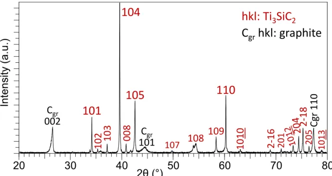
Going back to the Ti-Si-C system, a Ti3SiC2 matrix was produced by P-RCVD from totally
consumed SiC sub-layers and by increasing the dilution rate of TiCl4 in H2.8 The very first SiC
sub-layer deposited on the PyC interphase was, however, thicker than the others in order to protect the interphase and the fiber from the H2/TiCl4 attack. The same matrix coating was deposited
simultaneously on a graphite flat substrate and characterized by XRD. The pattern is typical of pure Ti3SiC2, SiC being hardly detectable (figure 6). The fracture surface observation shows that the PyC
interphase has allowed extended fiber pull-out (figure 7.a). The thin unconsumed part of the first SiC sub-layer can be observed against the interphase. The main part of the matrix with a thickness of ~2 µm corresponds to pure Ti3SiC2 with a typical plate-like microstructure (figure 7.b). The
SiC(f)/PyC/(SiC-)Ti3SiC2(m) microcomposites are non-brittle (figure 2.c) with an average strain at
failure up to the one of the Hi-Nicalon fiber (table 1). But the Young’s modulus of the microcomposites is well below that of the one of the sole fiber (270 GPa)14 whereas those of the
matrix components are above 300 GPa.15 This very low Young’s modulus is likely to be accounted
for by a matrix pre-microcracking resulting from the important coefficient of thermal expansion mismatch between the fiber and the Ti3SiC2 matrix (~9x10⁻⁶K-1).
CONCLUSION
PyC-free coating interphases could be deposited on Hi-Nicalon fibers by P-RCVD. A first difficulty relied on the protection of the fiber surface which was very sensitive to chemical attack by titanium containing-species. This difficulty could be circumvented through a first deposited SiC sub-layer thick enough to protect the surface of the fiber or with partially consumed Si-B-C sub-sub-layers. However, even if some delamination could be observed, the porous and multilayered (boro-)carbide coatings did not act as mechanical fuses in the SiC(f)/SiC(m) microcomposites. Microcomposites with
a PyC interphase and a Ti3SiC2 matrix could be also prepared and tensile tested at room temperature.
ACKNOWLEDGEMENT
This work was supported by the French national project NaCoMat and by Herakles. The AES analysis was performed by M. Lahaye at the "CeCaMA" from the University of Bordeaux 1. The author is indebted to his young coworkers from LCTS, namely O. Ledain and J. Couvin.
REFERENCES
1A. G. Evans and F. W. Zok, The physics and mechanics of fibre-reinforced brittle matrix composites,
J. Mater. Sci., 29 3857-96 (1994). https://doi.org/10.1007/BF00355946
2R. E. Tressler, Recent developments in fibers and interphases for high temperature ceramic matrix
composites, Composites Part A 30 429-37 (1999). http://dx.doi.org/10.1016/S1359-835X(98)00131-6
3H. W. Carpenter, J. W. Bohlen, Fibers coatings for ceramic matrix composites, Ceram. Eng. Sci.
Proc., edited by J. B. Wachtman (American Ceramic Society, Westerville, OH, 1992) 13 [7-8], 238-56 (1992). http://dx.doi.org/10.1002/9780470313954.ch26
4R. Naslain, The design of the fibre-matrix interfacial zone in ceramic matrix composites, Composites
Part A 29A 1145-55 (1998). http://dx.doi.org/10.1016/S1359-835X(97)00128-0
5R. R. Naslain, R. Pailler, X. Bourrat, S. Bertrand, F. Heurtevent, P. Dupel, F. Lamouroux, Synthesis
of highly tailored ceramic matrix composites by pressure-pulsed CVI, Solid State Ionics 141-142 541-48 (2001). http://dx.doi.org/10.1016/S0167-2738(01)00743-3
6O. Rapaud, S. Jacques, H. Di-Murro, H. Vincent, M.P. Berthet, J. Bouix, SiC/SiC minicomposites
with (PyC/TiC)n interphases processed by pressure-pulsed reactive CVI, J. Mater. Sci. 39 173-80
(2004). http://dx.doi.org/10.1023/B:JMSC.0000007742.34926.65
7C. Pallier, G Chollon, P. Weisbecker, F. Teyssandier, C. Gervais, F. Sirotti, Structural changes of
CVD Si–B–C coatings under thermal annealing, Surf. Coat. Tech. 215 178-85 (2013).
http://dx.doi.org/10.1016/j.surfcoat.2012.07.087
8S. Jacques, H. Fakih, J.-C. Viala, Reactive chemical vapor deposition of Ti3SiC2 with and without
pressure pulses: Effect on the ternary carbide texture, Thin Solid Films, 518 5071-77 (2010).
http://dx.doi.org/10.1016/j.tsf.2010.02.059
9C. B. Spencer, J. M. Córdoba, N. H. Obando, M. Radovic, M. Odén, L. Hultman, M. W. Barsoum,
The reactivity of Ti2AlC and Ti3SiC2 with SiC fibers and powders up to temperatures of 1550°C,
J. Am. Ceram. Soc. 94 1737-43 (2011). http://dx.doi.org//10.1111/j.1551-2916.2010.04332.x
10R. Naslain, J. Lamon, R. Pailler, X. Bourrat, A. Guette, F. Langlais, Micro/minicomposites: a useful
approach to the design and development of non-oxide CMCs, Composites Part A 30A 537-47 (1999). http://dx.doi.org/10.1016/S1359-835X(98)00147-X
11I. Jouanny, S. Jacques, P. Weisbecker, C. Labrugère, M. Lahaye, L. Maillé, R. Pailler, Synthesis of
TiC from porous carbon coating on Si-C-O (Nicalon) fibres by reactive chemical vapour deposition in pressure-pulsed mode or at atmospheric pressure, J. Mater. Sci. 45 6747-56 (2010).
http://dx.doi.org/10.1007/s10853-010-4769-9
12S. N. Patankar, Weibull distribution as applied to ceramic fibres, J. Mater. Sci. Lett. 10 1176-81
(1991). http://dx.doi.org/10.1007/BF00727897
13A. J. Perry, B. Ineichen, B. Eliasson, Fibre diameter measurement by laser diffraction, J. Mater.
Sci. 9 1376-78 (1974). http://dx.doi.org/10.1007/BF00551860
14A. R. Bunsell, A. Piant, A review of the development of three generations of small diameter silicon
carbide fibres, J. Mater. Sci. 41 823-39 (2006). https://doi.org/10.1007/s10853-006-6566-z
15P. Finkel, M. W. Barsoum, and T. El-Raghy, Low temperature dependencies of the elastic properties
FIGURES
Figure 1. SE SEM images of microcomposites with porous TiC interphases deposited on an unprotected fiber (a) and on a fiber protected with a SiC layer (b).
Figure 2. Tensile stress-strain curves at room temperature of representative microcomposites of the batches with PyC interphases (a), (b) and (c) and without a PyC interphase (d), (e) and (f). (For clarity curves are
offset horizontally.) 0 400 800 1200 1600 0 0.2 0.4 0.6 0.8 1 1.2 1.4 σ( M P a ) ε (%) (a) (b) (c) (d) (e) (f)
Figure 3. BSE (a) and SE (b) SEM images of the fracture surface of microcomposites with (SiBC-TiBC)n
interphase.
Figure 4. Fracture surface SE SEM images of microcomposites with a PyC interphase and a (SiBC-TiBC)n-SiC matrix.
Figure 5. AES depth profile analyses of the (SiBC-TiBC)n-SiC matrix.
0 20 40 60 0 1 2 3 atomic pourcentage Etch depth (µm)
C
KL1Si
KL1B
KL1Ti
LM4O
KL1Figure 6. XRD pattern of Ti3SiC2 deposited by P-RCVD on a flat graphite substrate.
Figure 7. Fracture surface SE SEM images of microcomposites with a PyC interphase and a Ti3SiC2 matrix.