HAL Id: hal-01947363
https://hal.archives-ouvertes.fr/hal-01947363
Submitted on 6 Dec 2018HAL is a multi-disciplinary open access archive for the deposit and dissemination of sci-entific research documents, whether they are pub-lished or not. The documents may come from teaching and research institutions in France or abroad, or from public or private research centers.
L’archive ouverte pluridisciplinaire HAL, est destinée au dépôt et à la diffusion de documents scientifiques de niveau recherche, publiés ou non, émanant des établissements d’enseignement et de recherche français ou étrangers, des laboratoires publics ou privés.
Beyond-5G wireless Tbps Scenarios and Requirements
Majed Saad, Carlos Faouzi Bader, Jacques Palicot, Yoann Corre, Gregory
Gougeon, Jean-Baptiste Doré
To cite this version:
Majed Saad, Carlos Faouzi Bader, Jacques Palicot, Yoann Corre, Gregory Gougeon, et al.. Beyond-5G wireless Tbps Scenarios and Requirements. [Research Report] BRAVE D1.0, ANR-BRAVE. 2018. �hal-01947363�
Back to Single-carrier for beyond-5G communications above 90 GHz
Grant agreement ANR-17-CE25-0013
Deliverable D1.0
Beyond-5G Wireless Tbps
Scenarios and Requirements
Delivery date
01/01/2018
Version
1.1
Editor
Majed Saad (CentraleSupélec)
Authors
CentraleSupélec: Majed Saad, Carlos F. Bader, Jacques
Palicot, Siradel: Yoann Corre, Grégory Gougeon, CEA-Leti:
Jean-Batiste Dore.
Dissemination
Public
Keywords
Tbps, Beyond 5G, use cases, scenario requirements
History
Version
Date
Modification
Author(s)
1.0
01/9/2018
First version
Majed Saad
Del. 1.0 – Scenarios and Requirements
Executive summary
The BRAVE project proposes to investigate innovative technologies allowing an efficient radio-communication usage of the 90GHz-200GHz spectrum. It will contribute to the emergence of ultra-high throughput and capacity beyond-5G (B5G) wireless communication systems. The wideband Single-Carrier (SC) waveform will be studied as an enabler for the migration of 5G networks towards Tbps systems. Achieving PHY-layer high spectrum efficiency under low energy consumption constraint is the main challenge.
The BRAVE project, defines six major PHY-related objectives: (i) the partners will elaborate analog and digital processing solutions that; (ii) operate above 90 GHz, based on; (iii) new efficient and ultra-wideband SC waveforms; the specific channel properties, and (iv) RF impairments are modelled and considered in the waveform design; (v) the integration into a simulation link- and system-level platform permits the assessment of the proposed technology in realistic scenarios; (vi) and, the project identifies the spectrum regulation constraints and requirements.
This document presents a description of some applicative scenarios and use cases in which ultra-high throughput (of order of Tbps) wireless communication systems are envisaged in bands above 90 GHz: kiosk download, wireless backhauling, Fixed Wireless Access (FWA), drones, server farm, hotspots with Augmented Reality (AR) or Virtual Reality (VR) multiple users, inter- or intra-chip communications. An insight on the spectrum availability to deploy such wireless communications is provided based on the French National Frequency Agency (ANFR) guidance and recommendations. Key performance indicators are also given to evaluate and compare the different achieved technical performances and solutions. A preliminary list of KPIs per scenario with system parameters and performance requirements is also provided in this technical deliverable. It is worth mentioning that depicted KPIs values constitute a preliminary and an early shaping of targeted parameters for future Tbps wireless communications, that still need to be validated and confirmed. The BRAVE project will contribute to this effort in further work packages (WP2 and WP3) mainly for scenarios as “kiosk”, FWA or mesh backhauling.
This document gives a first version of BRAVE spectrum opportunities and scenarios. The spectrum regulation aspects will be completed mid-2019 in deliverable D1.1, while the scenarios will be updated and finalized at the end of the project in deliverable D1.2.
Del. 1.0 – Scenarios and Requirements
Table of content
1 INTRODUCTION ... 5
1.1 VISION ... 6
1.2 5G AND BEYOND:APPLICATIONS AND USE CASES ... 7
1.3 SPECTRUM OPPORTUNITIES AND CONSTRAINTS ... 8
1.4 KPIS DEFINITION ... 9
2 USE CASES: DEFINITION AND REQUIREMENTS ... 11
2.1 KIOSK DOWNLOADING ... 11
2.2 BACKHAUL:MACRO AND SMALL-CELL ... 13
2.3 FIXED WIRELESS ACCESS ... 16
2.4 DRONES ... 18
2.5 SERVER FARM ... 19
2.6 VIRTUAL/AUGMENTED REALITY ... 20
2.7 INTER/INTRA-CHIP COMMUNICATION ... 21
3 PARTNERS INTERESTS ... 24
4 CONCLUSION... 25
Del. 1.0 – Scenarios and Requirements
List of Acronyms
5G 5th Generation AR Augmented Reality
B5G Beyond 5G
BW Bandwidth
CPE Customer Premises Equipment C-RAN Centralized Radio Access Network CPU Central Processing Unit
DL Down Link
eMBB enhanced Mobile BroadBand EIRP Equivalent Isotropic Radiated Power FSO Free Space Optical
FTTH Fiber To The Home FPS Frames per Second FWA Fixed Wireless Access KPI Key Performance Indicator LiDAR Light Detection and Ranging LoS Line-of-Sight
mMTC massive Machine Type Communications MIMO Multiple Inputs Multiple Outputs
NoC Network-on-Chip NLoS Non LoS
P2P Pear-to-Pear
P2MP Point-to-Multipoint communication RAM Random Access Memory
RF Radio Frequency Tx Transmitter / Transmit SoC System-on-chip
UAV Unmanned Aerial Vehicle UE User Equipment
UL Up Link
URLLC Ultra-Reliable and Low-Latency Communications VR Virtual Reality
Del. 1.0 – Scenarios and Requirements
1 Introduction
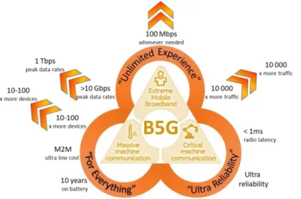
The 5G mobile technology is targeting to support three main uses cases: massive Machine Type Communication (mMTC), ultra-Reliable Low Latency Communication (uRLLC) and enhanced Mobile Broadband (eMBB) as shown in Figure 1. These use cases have several constraints such as the demands of a higher data rate that allow data hungry application, the increasing traffic capacity from subscribers\ devices, the introducing of application with more stringent constraints in latency, power consumption and\or cost. These 5G services are partitioned according to their critical requirements that allow to overcome them by relaxing other parameters.
Figure 1 : 5G expected increase and beyond key requirements
Furthermore, the wireless data traffic is projected to increase by 1000-fold by the year 2020 [1] and is likely to grow by more than 10 000-fold by the year 2030 [2], similarly, the required data rates are increasing continuously towards Tbps. Thus, the unlimited experience for beyond 5G wireless system will rise towards new limits as shown in Figure 1 and Figure 2.
Del. 1.0 – Scenarios and Requirements
In brief, the wireless data rates have doubled every 18 months over the last three decades and the wireless terabit-per-second (Tbps) links will become a reality within the next 5 years.
This deliverable is organized as follows. In this chapter, the vision towards beyond 5G will be introduced then the potential application and use cases that require the ultra-high data rate will be listed. In addition, the spectrum opportunities and constraints will be determined. Moreover, we give the description of the Key Performance Indicators (KPI) that are used for use cases evaluation and definition. In Chapter 2, we give a detailed description of each use case including all requirements and system KPI. Finally, the use case priorities decided by the partners for BRAVE investigations and demonstrations are presented in Chapter 3.
1.1
Vision
Although the 5G specification and development work is still ongoing, and a large amount of imprecision still exists, there are also large amounts of concepts that are considered to become reality in 5G phase 1 networks by 2020/5. To meet this incredible projected increase in traffic demand (capacity), throughput in wireless networks must be increased by:
Cell densification: shrinking cell sizes and large deployment of small-cells with associated interference mitigation,
Greatly increasing spectral efficiency,
Additional spectrum, including millimetre-wave bands, Cloud RAN higher efficiency
In addition, it is recognized that some of these topics may undergo evolutions for deployment in 5G networks. However, regardless of the dimension of 5G developments, they will remain a research issue for further evolutions.
The unsatisfied requirements and applications will be pushed to beyond 5G (B5G), and future applications and technologies will be integrated when they achieve maturity and finally, these systems must be able to handle the continued trends in requirements over next years.
Moreover, B5G scenarios consider more stringent application requirements such as ultra-higher data rate, a higher number of devices, and even denser networks. The effort for achieving these requirements must be done at the same pace on the user access and backhauling segments to avoid any bottleneck effect. As for 5G deployments, acquiring additional spectrum and the availability of large spectrum are the basis to reach the future requirements of B5G systems. For this reason, the research in this project BRAVE is focused on the millimetre wave and sub-THz band above 90GHz where a huge bandwidth can be allocated for each user. Nowadays, other researchers are investigating the feasibility of communication on higher frequencies on the true THz band [4] [5].
The BRAVE project [6] [7], has been launched in early 2018 with the aim to create and evaluate new radio technologies that would operate in the 90-200 GHz spectrum and support B5G performance. The BRAVE ultimate goal is the definition of a solution that would reach 1 Tbps (100x peak data rate defined in
Del. 1.0 – Scenarios and Requirements
2020 for 5G). Considering the adversary nature of a communications channels in frequencies above 90 GHz, the project focusses on scenarios in which the connected nodes (end user, relay, access point, gateway) are in line-of-sight (LoS) or nearly LoS (i.e. only light obstruction).
In addition, BRAVE technology will be based on a new Single-Carrier waveform [8] using a large bandwidth allocated in the 90-200 GHz spectrum and exploiting the frequency-flat channels that are made possible with sparse multipath and thin beamforming.
1.2
5G and beyond: Applications and use cases
Wireless data rates are increasing over time and we will require a Tbps in the future. This is mainly driven by the need for having to move files of ever-increasing size, as well as for downloading streaming\podcast services. Several use cases have been identified for which Tbps systems are of interest:
Data kiosk application: very short-range with very-high data rate link; Inter/Intra-chip communication;
Resolution of congestion issues in server farms;
Small range hot-spots delivering high-speed data to demanding applications such as augmented or virtual reality;
High-capacity wireless mesh backhauling for dense access networks and connected cities;
Wireless fixed mesh backhaul infrastructure to deliver ultra-high data throughput and capacity within a connected city, towards offices, houses or hotspots.
The wireless infrastructure is needed as an alternative to optical fiber deployment to avoid any bottleneck in the backhaul. The ultra-high speed is required to serve the smart city devices (e.g. video-surveillance as part of the internet of objects) or public internet access. The envisioned ultra-dense network topology in urban areas with the extreme data rate, capacity and latency requirements makes the fiber-based backhauling highly desirable, but sometimes complicated due to current fiber networks penetration (variable from one country to the other) and related extension cost. High data rate wireless backhauling is a valuable competitive technology, which benefits from lower deployment costs and constraints.
Furthermore, terabit/s communications will open new (partly unexpected) services and application opportunities. Therefore, other use cases and market perspectives can be investigated in the future. Some of the mentioned use cases are defined by the IEEE 802.15 standard [9] [10] in the band between 250-325 GHz, IEEE 802.11ad in the 60 GHz [11] and by others at 60-300 GHz where the targeted rate was up to 100 Gbps [3]. However, the foreseen required rate in the near future will extend towards Tbps, as for example, the 100 Gbps rate is enough for virtual\augmented reality and kiosk for a single user but not enough for multiple simultaneous users and instantaneous large file download. Moreover, several researchers tried to reach this rate, but the maximum achieved rate due to hardware and technology limitation was below 60 Gbps [12], to the best of our knowledge, so additional breakthrough technologies are necessary to reach the B5G throughput requirements.
Del. 1.0 – Scenarios and Requirements
In general, the scenarios of interest constraints to static or nomadic use cases (low mobility) with short-range communication due to beam tracking issues and high propagation losses at high frequencies. BRAVE technology will support advanced wireless scenarios that are not covered by the 5G target performance regarding peak data rate (several Gbps) and/or capacity (10 Tbps/km²). Beyond-5G latency and improved energy efficiency could be reached as well.
1.3
Spectrum opportunities and constraints
The frequency spectrum above 90 GHz offers opportunities for huge bandwidths, up to several tens of GHz, which is required to increase data rates and network capacities beyond 5G performance. The BRAVE partners are investigating frequencies in range from 90 to 200 GHz.
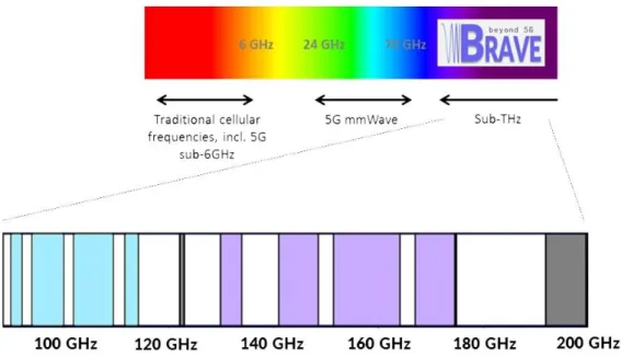
The radio spectrum above 90 GHz is today essentially known for being used by scientific services (e.g. astronomy observation, earth exploration and satellite services, meteorology, etc.) and has never been used effectively for radio wireless communications purposes. It should however be noted that the radio regulations already allocated several frequency bands above 90 GHz to the fixed and mobile services. More specifically, within the range 90 – 200 GHz, the following frequency bands would provide opportunities to be considered for introducing terrestrial communication systems (Figure 3):
92 – 94 GHz, 94.1 – 100 GHz, 102 – 109.5 GHz, 111.8 – 114.25 GHz, 122.25 – 123 GHz, 130 – 134 GHz, 141 – 148.5 GHz, 151.5 – 164 GHz, 167 – 174.5 GHz, 174.5 – 174.8 GHz, 191.8 – 200 GHz.
Up to 58.1 GHz bandwidth could be made available for new wireless communication services.
It can also be noted, that there is some ongoing work within CEPT (European Conference of Postal and Telecommunications Administrations) aiming to facilitate the deployment of fixed services links in the frequency ranges 92 – 115 GHz and 130 – 175 GHz.
Del. 1.0 – Scenarios and Requirements
Figure 3 : Frequency allocation for wireless communications in BRAVE considered spectrum Finally, it is expected that the coexistence with scientific applications (in-band or out-of-band interferences) can be managed with reasonable effort and few constraints, as those applications are precisely localized. For instance, the only radio-astronomy telescope in France is the interferometer positioned on the “Plateau de Bure”, in the Alps.
1.4
KPIs definition
In this subsection, the scenario and system KPI are defined. These KPIs are the basis for the use cases described in the next Chapter.
Scenario Parameters:
Environment: Indoor\Outdoor Coverage range
Link visibility: LoS\nLoS User mobility: Stationary\Low Environment mobility
Network type: Multi-cell, mesh multi-points, etc. Maximum number of simultaneous users
Constraints: Dimension, Power, Cost, …
Del. 1.0 – Scenarios and Requirements
Aggregated DL/UL data rate (or capacity) (Gbps) Peak DL/UL user data rate (Gbps)
Minimum user-plane latency (ms) Energy efficiency (pJ/bit)
Required spectrum Efficiency (bps/Hz) Required bandwidth (GHz)
Required reliability
DL/UL Tx power (W or dBm) DL/UL maximum antenna gain (dBi) Feasible MIMO size
Del. 1.0 – Scenarios and Requirements
2 Use cases: Definition and Requirements
2.1
Kiosk downloading
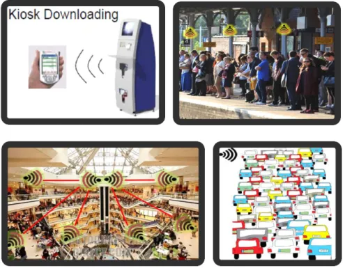
The need for moving files of increasing size necessitates having some stations with ultra-high data rate. These stations are named data kiosk and they can be distributed in public places to serve one user in a short duration (Point-to-point P2P) or several users (point-to-multipoint) simultaneously in crowded places such as airport gate, train station, shopping malls and traffic jams. This kind of machine requires an aggregated data rate in order of Tbps to allow file downloading to users’ equipment (UE) in short time, for example, a single user can download instantaneously a file from his wish-list while passing the entrance ports of train station and several users in the crowded waiting area can be served by the data showers as shown in Figure 4.
Figure 4 : Data kiosk scenarios
Moreover, the data kiosk can be also distributed in fuel station and in the road where traffic jams are very often so that the cars can update the firmware and download any multimedia content for the car (3D 4K map video) and for the in-car passengers.
The data offloading by using the data kiosk reduces the burden of networks and the number of users connected to the network operator. The data kiosk is connected to the backbone network by fiber optics and it can store locally the top trending files as an example a data kiosk can be as a vending machine at the library\video shop that stores the most downloaded movies, software, and large files.
In any case, the data kiosk application is limited to short distances from few centimetres up to few meters, where the channel is mostly frequency flat due to the line-of-sight (LoS) or near LoS communication. However, in some scenarios, the channel degrades due to reflections and multipath
Del. 1.0 – Scenarios and Requirements
fading. Moreover, in most cases, the user is stationary or pedestrian, so he/she is in low mobility while interacting with Kiosk that limits the Doppler shift.
The high data rates are mostly required on the downlink, and the user will need only the uplink to establish the connection and for control information during the download. So, the communication in this use case is asymmetric. The high data rate uplink (UL) also is required to do backup to cloud as example but the UL transmission is very challenging for a mobile device with limited power.
In addition, the constraints on the devices are of different levels. We can define three levels depending on the equipment. Firstly, the transmitter data kiosk machine has relaxed constraints compared to handheld devices as phones and tablets. They are relaxed because the data kiosk is directly connected to a power outlet, it can also support a higher complexity (higher cost) and has a larger dimension that allows a larger system and antenna array and it permits using a cooling system if needed. Secondly, the cars as an example have a medium level of constraints due to moderate relaxation in power consumption and complexity. Thirdly, the handheld devices such as mobile phones and tablets have more severe requirements and constraints because they are highly limited in complexity (cost), power consumption (battery powered) and dimension that limits the overall system size and the antennas position.
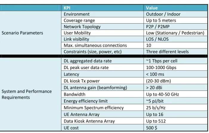
In brief, all the KPI are summarized in Table 1 to define the data kiosk use case and to highlight the UE and kiosk requirements to reach Tbps with the available bandwidth under the constraints of low power consumption and complexity.
Table 1 : KPIs for the data kiosk use case
KPI Value
Scenario Parameters
Environment Outdoor / Indoor
Coverage range Up to 5 meters
Network Topology P2P / P2MP
User Mobility Low (Stationary / Pedestrian)
Link visibility LOS / NLOS
Max. simultaneous connections 10
Constraints (size, power, etc) Three different levels
System and Performance Requirements
DL aggregated data rate ~1 Tbps per cell DL peak user data rate 100-1000 Gbps
Latency < 100 ms
DL kiosk Tx power (20-30 dBm)
DL antenna gain (beamforming) > 20 dBi
Bandwidth Up to 40-50 GHz
Energy efficiency limit ~5 pJ/bit Minimum Spectrum efficiency 25 b/s/Hz
UE Antenna Array Up to 16
Data Kiosk Antenna Array Up to 512
UE cost 500 $
The data kiosk application gets more attention and it was studied by IEEE P802.15 Working Group for Wireless Personal Area Networks for the amendment IEEE 802.15.3d [10] in the band between 275-325
Del. 1.0 – Scenarios and Requirements
GHz and it was studied in mmWave at 60 GHz [13]. However, in the BRAVE project, we will focus on the carrier frequency between 90 GHz and 300 GHz where we can get a larger bandwidth and it can be implemented by the current technology.
2.2
Backhaul: Macro and small-cell
The mobile traffic is constantly growing with a sevenfold increase forecast from 2016 to 2021 [14]. Smartphone traffic will even exceed PC traffic by 2021. Busy-hour internet traffic is growing more rapidly than average internet traffic. Several applications will require radio sites to support tens of Gbps and backhaul them to the core network:
Deployment of 5G hotspots delivering some Gbps using the millimetre wave bands Centralized Radio Access Network (C-RAN) with huge data on the fronthaul
Cloud computing
Ultra-Reliable and Low-Latency Communications (URLLC) for autonomous vehicles for instance Wireless backhaul above 100 GHz promises capacity up to 100Gbps [15]. The BRAVE technology is
thus a candidate to improve more the backhaul.
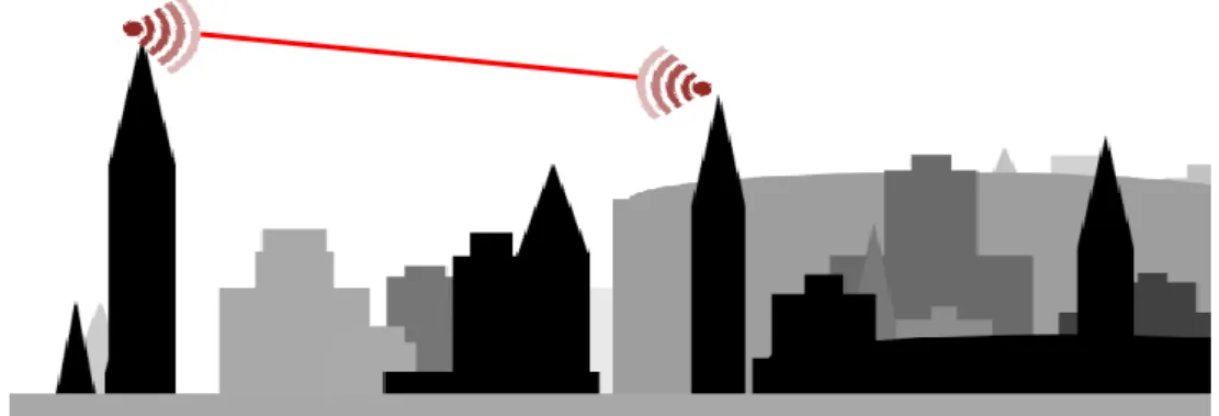
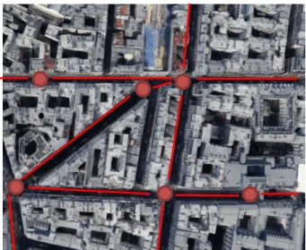
Two topologies will be analysed during the project: the point-to-point macro backhaul link with both terminals located on high buildings (Figure 5), and the street-level mesh backhaul interconnecting small cell remotes with multi-hop and redundant links (Figure 6).
Del. 1.0 – Scenarios and Requirements
Figure 6 : Street-level mesh backhaul The main factors that impact in the propagation loss are as follows:
Frequency: the loss in dB includes a 20.log10 (f), to be compensated by high directive antennas with large gain.
Atmospheric gases: as shown on Figure 7, the attenuation keeps increasing beyond 90 GHz, with a peak of almost 30 dB/km around 185 GHz, which is in the scope of BRAVE. This is of particular importance for macro point-to-point backhaul scenario where the distance can be a few kilometres.
Rainfall: Figure 8 shows the attenuation due to the rain is increasing rapidly below 100 GHz but could be almost constant above. This affects the availability of the backhaul, especially in the macro point-to-point scenario where the distance can be a few kilometres.
Vegetation: Figure 9 shows the attenuation due to the vegetation up to 30 GHz, which raises up to some dB/m. This is of particular importance for the street-level mesh backhaul scenario where low terminals can be obstructed by trees. A fine description of the vegetation is required for simulation, which can be obtained thanks to LiDAR data as shown in Figure 10 where strong ray paths can be predicted below foliage.
Del. 1.0 – Scenarios and Requirements
Figure 7 : Attenuation by atmospheric gases [16] Figure 8 : Rain attenuation [17]
Figure 9 : Vegetation attenuation [18]
Figure 10 : Multipath prediction for a street-level backhaul link
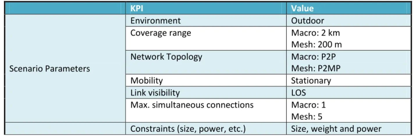
In brief, all the KPI are summarized in Table 2 to define the backhaul use case. Table 2 : KPIs for the backhaul use case
KPI Value
Scenario Parameters
Environment Outdoor
Coverage range Macro: 2 km
Mesh: 200 m
Network Topology Macro: P2P
Mesh: P2MP
Mobility Stationary
Link visibility LOS
Max. simultaneous connections Macro: 1 Mesh: 5
Del. 1.0 – Scenarios and Requirements
constraints for mesh equipment
System and Performance Requirements
Aggregated data rate ~1 Tbps per node
Peak data rate Macro: 1 Tbps
Mesh: 200 Gbps
Latency < 100 ms
Tx power Macro: 10 W (40dBm)
Mesh: 1 W (30 dBm) Antenna gain (beamforming) > 25 dBi
Bandwidth Up to 40-50 GHz
Reliability In case of dual-connectivity: 99.9% service availability Without dual-connectivity: 99.999% service availability
Antenna Array Macro: up to 1024
Mesh: up to 256
Node cost 1000 $
2.3
Fixed Wireless Access
The increasing demand for very high data rates also affects the broadband service to homes and enterprises. Traditionally addressed with wireline solutions, xDSL technology becomes insufficient and Fiber To The Home (FTTH) reaches the limits for viable deployment costs because of the last mile complexity. Fixed broadband access is thus expected to connect 30% of worldwide households with fiber by 2023 [19], opening opportunities for Fixed Wireless Access (FWA).
Indeed, wireless network performance keeps improving, especially with 5G, making FWA now competitive. The network cost (cost per delivered bit) keeps dropping, enabling a viable business case for FWA. The BRAVE technology will enable to overcome another gap in data rates.
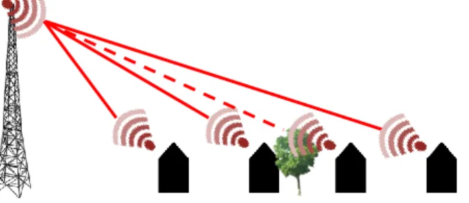
The point-to-multipoint link will be analysed in two environments: the urban case (Figure 11) and the suburban case (Figure 12). The main factors identified in the propagation loss are the same as described in the backhaul scenario, i.e. the frequency, the atmospheric gases, the rain and the vegetation. The Customer Premises Equipment (CPE) will be located outdoor has no penetration is envisaged at BRAVE frequencies. The shadowing by buildings (urban case) and vegetation (suburban case) will constrain the deployment to maximize LoS between the base station and the CPE.
Del. 1.0 – Scenarios and Requirements
Figure 11 : Urban point-to-multipoint FWA
Figure 12 : Suburban point-to-multipoint FWA In brief, all the KPI are summarized in Table 3 to define the FWA use case.
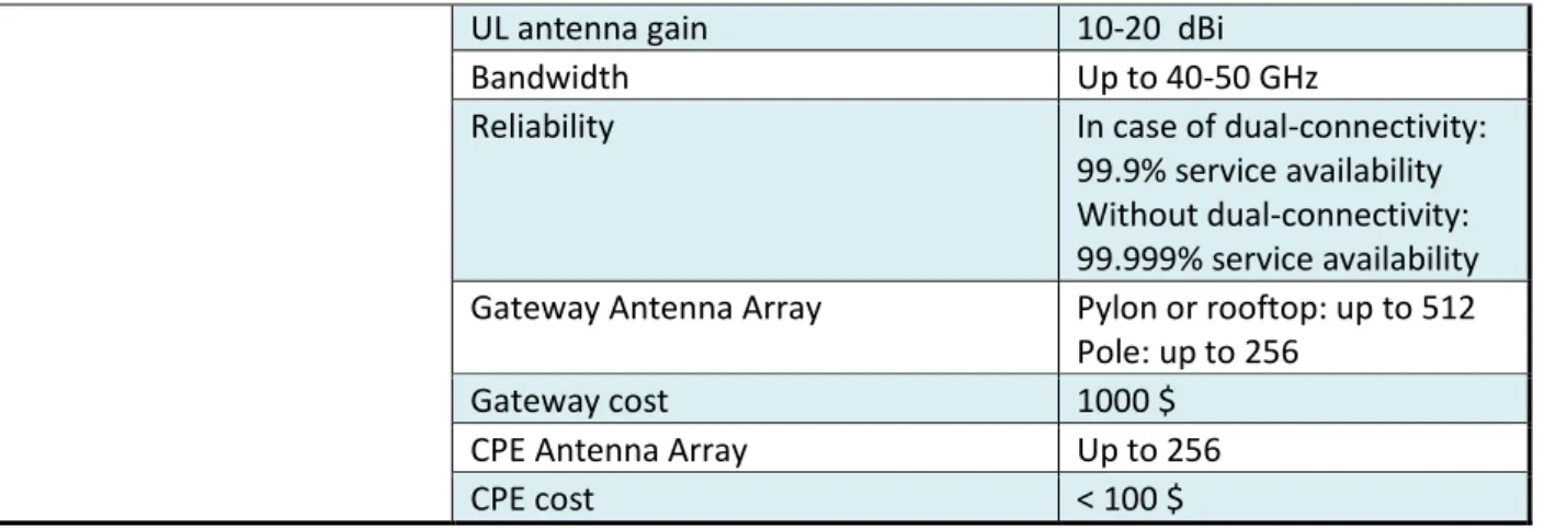
Table 3 : KPIs for the FWA use case
KPI Value
Scenario Parameters
Environment Outdoor
Coverage range Urban: 100 m
Suburban: 500 m
Network Topology P2MP
User Mobility Stationary
Link visibility LOS / nearly LOS
Max. simultaneous connections 100
Constraints (size, power, etc) Size, weight and power constraints for equipment installed on small poles Low cost CPE
System and Performance Requirements
DL aggregated data rate ~1 Tbps
DL user data rate 10 Gbps
Latency < 100 ms
DL gateway power 1 - 10 W (30 - 40 dBm) DL antenna gain (beamforming) > 20 dBi
Del. 1.0 – Scenarios and Requirements
UL antenna gain 10-20 dBi
Bandwidth Up to 40-50 GHz
Reliability In case of dual-connectivity: 99.9% service availability Without dual-connectivity: 99.999% service availability Gateway Antenna Array Pylon or rooftop: up to 512
Pole: up to 256
Gateway cost 1000 $
CPE Antenna Array Up to 256
CPE cost < 100 $
2.4
Drones
The deployment of drones (or UAV) for providing very high data rate connectivity during a particular time-limited event is another scenario of interest, either for intervention of security forces, for unpredicted safety operations, or for an organized event. This scenario is still marginal today but will undoubtedly be a common solution in the future [19b], in particular when autonomous flying will be operational.
The BRAVE data rate and capacity are required in case the drone is employed as a hub in an xhaul architecture (possibly meshed):
Xhaul towards local portable or mobile access points; Xhaul towards the drone, which brings the access point.
We can imagine the “drone as a hub” is using the sub-THz frequencies as a “premium” solution but complementary to lower frequencies. This spectrum is exploited when LoS or short range is reached, and more likely when the drone is stationary. The LoS situation can be maximized by positioning the drones (or some of them) above the building roofs, and/or by creating a LoS mesh architecture into an automated and intelligent way.
Del. 1.0 – Scenarios and Requirements
When looking at the requirements, the main differences compared to the backhaul scenario are in the antenna size (to be kept limited, along with low weight), the power consumption (to be minimized), and the processing capabilities.
Besides, the spectrum usage will be strongly constrained, either to frequency slots reserved to safety operations, or by the presence of primary networks.
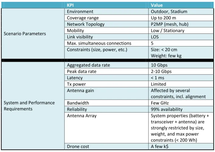
Table 4 : KPIs for the drone use case
KPI Value
Scenario Parameters
Environment Outdoor, Stadium
Coverage range Up to 200 m
Network Topology P2MP (mesh, hub)
Mobility Low / Stationary
Link visibility LOS
Max. simultaneous connections 5
Constraints (size, power, etc.) Size: < 20 cm Weight: few kg
System and Performance Requirements
Aggregated data rate 10 Gbps
Peak data rate 2-10 Gbps
Latency < 1 ms
Tx power Limited
Antenna gain Affected by several
constraints, incl. alignment
Bandwidth Few GHz
Reliability 99% availability
Antenna Array System properties (battery + transceiver + antenna) are strongly restricted by size, weight, and max power constraints (< 200 Wh)
Drone cost A few k$
2.5
Server farm
Server farms are becoming a part of the computing infrastructures of most companies. The concept of server farm network is receiving an increased attention. Most architectures deployed today are wired networks. Copper and optical fiber cables are used for intra- and inter-rack connections in the network. The design of an efficient high-speed/high-bandwidth network to meet the high computing and communication demands is critical. The architecture must also satisfy several requirements such as scalability, low latency, availability, and minimum cost [20]. Other practical concerns, including cabling complexity, power consumption, and cooling, must be also counted for in the design [21]. Moreover, as described in [20] the network must be adaptable to respond to dynamically changing and evolving traffic patterns.
Wired networks face two problems: cabling complexity and hotspots [20]. Few nodes in a server farm may contain data blocks that are required by many jobs. Such nodes are referred as hotspots [20]. In case
Del. 1.0 – Scenarios and Requirements
of tree-based network interconnection architecture, it is very difficult to adapt to unpredictable traffic patterns resulting from. Inadequate network capacity and oversubscribed links can lead to flow congestions. It can cause increased programming effort and reduction in concurrency of execution of applications, and thus overall network performance degradation. Since it is difficult to predict the demand, and in order to accommodate the worst-case scenario, an over-deployment of copper and optical fiber cables is needed.
This fact has motivated the researchers to investigate the feasibility of establishing wired or wireless on-demand links to support elephant flows in oversubscribed server farm network as a different approach to tackle the hotspot problem [20]. In case of wired on-demand links, commodity electrical switches are deployed to connect a subset of nodes and provide on-demand wired links when needed. Wired solutions require the deployment of larger number of cables, which may escalate cabling complexity problems (e.g., cable management, maintenance, and heat dissipation).
The potential capability of establishing flexible on-demand wireless links has motivated the researchers to investigate wireless communication as a possible solution for hotspot and cabling complexity problems (see [20] for a complete state of the art). Two technologies candidates are under investigation, 60GHz as well as the Free Space Optical (FSO) [20]. Sub-THz wireless link can also be a candidate bridging the gap between advantages and weakness of 60GHz and FSO technologies. In one hand, one can expect to design spectrally efficient system with the advanced modulation and coding techniques widely considered in mmWave as well as in sub 6GHz band while FSO spectral efficiency is very low (e.g. On off keying modulation). On the other hand, the use of sub-THz band allows larger signal bandwidth (40-50GHz) with respect to 60GHz (7GHz). Finally, yet importantly, the good security attribute of sub-THz (resp. FSO) technology due to the “bad” propagation condition is an unconditional benefit.
In brief, all the KPI are summarized in Table 5 to define the server farm use case. Table 5: KPIs for the server farm use case
KPI Value Scenario Parameters Environment Indoor Coverage range < 10m Network Topology P2P Mobility Stationary
Link visibility LOS
System and Performance Requirements
Peak data rate ~1 Tbps
Latency < 0.1 ms
Tx power 100 mW - 1 W (20 - 30dBm)
Antenna gain (beamforming) > 20 dBi
Bandwidth Up to 40-50 GHz
Cost 100 $
2.6
Virtual/augmented reality
For the last forty years, interactive 3D graphics have focused on the “Skinetic depth effect” so that the image presented by the three-dimensional display changes in exactly the same way that the image of a
Del. 1.0 – Scenarios and Requirements
real object would change for similar motions of the user's head (Sutherland et al [1]). This basic metaphor has been the driving force behind “Virtual Reality” and the immersion in virtual environments.
Most of VR and AR devices employ a variety of sensors, enabling them to perceive orientation, acceleration, location, temperature, as well as recording audio and video. More importantly, they can connect to remote services, share collected data, and exploit resources offered by cloud services. As in many real-time applications, AR offloading is bandwidth and especially delay constrained. This scenario is much closed to the offloading scenario already discussed.
Concerning throughput and latency required for AR and VR application. The authors of [22] have performed a detailed analysis:
“Several studies suggest that the human eye transmits around 6 to 10 Mb/s to the brain by taking into account that accurate data is available only for the central region of the retina (a circle whose diameter is 2 degrees in the visual field). However, there is no way to isolate this area on video frames and full frames have to be processed. If we consider that the field of view of a smartphone’s camera is between 60 to 70 degrees, a rough estimate of the amount of data to transmit is around 9 to 12 Gb/s. In practice, an uncompressed 60 FPS, 12 bits per pixel video with a resolution of 3840 x 2160 (4k) presents a bit rate of 711 Mb/s, which can drop to 20-30 Mb/s when compressed with lossy algorithms. We estimate the minimal bandwidth to be in the order of 10 Mb/s for a video feed with enough information to perform advanced AR operations”.
However, as the computing resources may be limited on portable/wearable devices (e.g. smart glasses), one can expect to perform the video processing (video decoding) at the edge of the network. Consequently, the throughput to transmit is around 9 to 12 Gbps making the use of current technology not possible.
Concerning the latency, a consensus converges to a threshold of 10 ms in order to preserve the integrity of the virtual environment and prevent phenomenon such as motion sickness [22] (while pointing out that some latency can be hidden behind mechanisms such as motion prediction). The required KPI are like those described in the “data kiosk” scenario.
2.7
Inter/intra-chip communication
The board-to-board and System/network-on-chip (SoC/NoC) communication is an Inter/Intra-chip communication that needs an ultra-high data rate [23]. An example is video camera where the required data rate is 200 Gbps for the following video format: 120 Hz frame rate of 48-bit pixel resolution 4320x7680. In addition, the available copper wires connection nowadays cannot reach Tbps and soon it will be the bottleneck, so it will limit the development of a faster system. Moreover, the current approach in the development of a more powerful system is the parallelization that necessitates chips collaboration as nowadays multicore computer chips. Thus, the communication across processing cores for high-performance computing architectures as shown in Figure 14 is congested, needs a high rate and it is hard to route without high copper losses due to longer paths. Moreover, the 3D Chip Stacking is now viable as shown in Figure 15 that includes all required chips in a transceiver up to the antenna on-chip at the top
Del. 1.0 – Scenarios and Requirements
layer. In the stacked chip, the parasitic vertical wiring to the device level is crucial at high frequencies that give another opportunity to the wireless connection by some holes through all the layers.
Figure 14 : Processing cores for high-performance computing architectures
Figure 15 : Samsung 3D chip stack
Thus, the connection between the different chips and boards is simplified by means of wireless beam steering so it can enable more parallel links and it allows for pin count reduction. However, the copper boards induce some multipath reflections of less than -20 dB as compared to the LoS component according to the measurement done in TU Dresden.
The constraints are of a moderate level compared to the mobile phone in the kiosk application because the coverage range is reduced to few centimetres that decrease the required radiated power. The power consumption constraints depend if the device is battery powered as laptops and cameras or not as servers. Moreover, the LoS link is always available by direct link or by using some reflectors and the environment between board/chips are static. However, a strong constraint in this use case is the latency where it should be like existing wired latency as an example those used between CPU and RAM.
The KPIs for inter/intra-chip communication are summarized in Erreur ! Source du renvoi introuvable.. Note that the antenna array size is limited by the chip area in case of 3D chip stacking and by the carrier frequency that affects the antenna size.
Del. 1.0 – Scenarios and Requirements
Table 6 : KPIs for the inter/intra-chip communication use case
KPI Value
Scenario Parameters
Environment Indoor
Coverage range Up to a few centimetres
Network Topology P2P / P2MP
User Mobility Stationary
Link visibility LOS
Max. simultaneous connections 5
System and Performance Requirements
Aggregated data rate 0.5-1 Tbps
Peak data rate 100-1000 Gbps
Latency < 300 ns
Tx power 100 mW
Antenna gain <3dBi
Bandwidth Up to 40-50 GHz
Energy efficiency limit ~100 pJ/bit Minimum Spectrum efficiency 25 b/s/Hz
Antenna Array Up to 256
Del. 1.0 – Scenarios and Requirements
3 Partners interests
Several use cases and scenarios of interest with several hundreds of Gbps or Tbps systems operating above 90 GHz have been already detailed in previous section. To what concerns the project BRAVE scenarios are divided into three groups:
L1 (level 1): Scenarios for which the BRAVE technology can be an asset or enabler;
L2: Scenarios of special interest for the project’s partners, which will be considered for definition and evaluation of the BRAVE solution;
L3: Scenarios that will be implemented in the BRAVE demonstration framework. The hereafter table synthetizes the level of BRAVE’s partners focus and involvement.
Table 7 : Level of the BRAVE partners focuses and involvements
Scenario Kiosk Macro Xhaul
Small-cell mesh Xhaul
FWA Drones Server
farm VR/AR inter/intr a-chip L1 -- L2 -- -- -- -- L3 -- -- -- -- -- In the context of the project BRAVE some of the above scenarios are most relevant in terms of technology and value, and will be the basis for research, evaluation, and demonstration. The main scenarios under interest are :
i. Kiosk scenario: with very short-range (up to few meters) with very-high data rate link; ii. Resolution of congestion issues in server farms;
iii. Small-range hot-spots with limited user mobility and demanding applications like virtual or augmented reality, high-resolution video;
iv. Wireless fixed mesh backhaul infrastructure to deliver ultra-high data throughput and capacity within a connected city, towards offices, houses or hotspots (as an alternative to optical fiber deployment), smart city devices (e.g. video-surveillance as part of the internet of objects) or public internet access.
Consequently, the challenges faced by BRAVE partners are on the spectral efficiency (up to 25 bps/Hz), energy efficiency (up to 5 pJ/bit), capability to serve many users simultaneously (e.g. into FWA or hotspot scenarios), while limiting the effect of interferences.
It’s worth to highlight that depicted KPIs in section 2 may be adjusted after their deep analysis by identifying and considering the effects of RF hardware, propagation channel and energy consumption impairments that could limit depicted theoretical “predicted” link capacity (among others parameters) in the frequencies above 90 GHz band. Therefore, a deeper insight analysis will be provided by the BRAVE’s consortium in next deliverables of WP2 and WP3.
Del. 1.0 – Scenarios and Requirements
4 Conclusion
Deliverable D1.0 is paving the way to the technical and demonstration activities conducted into the BRAVE project, by specifying the frequency bands to be considered, the target requirements, the relevant KPIs and B5G scenarios.
This document gives a first version of BRAVE spectrum opportunities and scenarios. The spectrum regulation aspects will be completed mid-2019 in deliverable D1.1, while the scenarios will be updated and finalized at the end of the project in deliverable D1.2.
Del. 1.0 – Scenarios and Requirements
References
[1] A. Ghosh et al., “Millimeter-wave Enhanced Local Area Systems: A High-data-rate Approach for Future Wireless Networks”, IEEE Journal on Selected Areas in Communications, vol. 32, no. 6, June 2014.
[2] I. d. T. Rui, and L. Aguiar, White Paper for Research Beyond 5G, 2015.
[3] G. Fettweis, F. Guderian, and S. Krone, “Entering the Path Towards Terabit/s Wireless Links,” Design, Automation & Test in Europe, 2011.
[4] I. F. Akyildiz, J. M. Jornet and C. Han, “Terahertz Band: Next Frontier for Wireless Communications,” Physical Communication (Elsevier) Journal, vol. 12, pp. 16-32, September 2014.
[5] I. F. Akyildiz, J. M. Jornet, and C. Han, “TeraNets: Ultra-broadband Communication Networks in the Terahertz Band”, IEEE Wireless Communications Magazine, vol. 21, no. 4, pp. 130-135, August 2014. [6] J.-B. Doré, Y. Corre, S. Bicais, J. Palicot, E. Faussurier, D. Kténas, and F. Bader, “Above-90GHz Spectrum and Single-Carrier Waveform as Enablers for Efficient Tbit/s Wireless Communications,” in Proc. of the 25th International Conference on Telecommunication. (ICT), France, June 2018.
[7] BRAVE project website, http://www.brave-beyond5g.com/.
[8] J. Palicot, and F. Bader, “Backing to Single Carrier in Tera Hertz Communications for Green Considerations,” in Proc. of the 32nd International Union of Radio Science (URSI’2017) GASS, Montréal, Canada, August 2017.
[9] T. Kürner, “TG3d Applications Requirements Document (ARD)”, IEEE P802.15 Working Group for Wireless Personal Area Networks (WPANs), May 2015.
[10] IEEE Std 802.15.3d-2017, IEEE Standard for High Data Rate Wireless Multi-Media Networks, Amendment 2: 100 Gb/s Wireless Switched Point-to-Point Physical Layer, IEEE, 2017.
[11] IEEE Std 802.11ad, Amendment 3: Enhancements for Very High Throughput in the 60 GHz Band, 2012. [12] I. Ando, M. Tanio, M. Ito, T. Kuwabara, T. Marumoto, and K. Kunihiro, “Wireless D-band communication up to 60 Gbit/s with 64QAM using GaAs HEMT technology,” in the Proc. of the IEEE Radio and Wireless Symposium (RWS), 2016.
[13] IEEE Std 802.15.3e-2017, IEEE Standard for High Data Rate Wireless Multi-Media Networks, Amendment 1: High-Rate Close Proximity Point-to-Point Communications, 2017.
[14] Cisco, Cisco Visual Networking Index: Forecast and methodology, 2016-2021, June 2017. [15] Ericsson, Ericsson technology review: Microwave backhaul beyond 100 GHz, February 2017. [16] ITU-R P.676-10, Attenuation by atmospheric gases, September 2013.
[17] E-band communications, available at: http://www.e-band.com/index.php?id=86. [18] ITU-R P.833-9, Attenuation in vegetation, September 2016.
Del. 1.0 – Scenarios and Requirements
[19b] Z. Becvar, M. Michal, P. Pavel, J. Plachy, and D. Gesbert, "Performance of mobile networks with UAVs: can flying base stations substitute ultrar-dense small cells?", 23rd European Wireless (EW 2017), Dresden, Germany, May 2017.
[20] S. Hamza, Jitender S. Deogun, and Dennis R. Alexander, “Wireless Communication in Data Centers: A Survey”, IEEE Communications Survey & Tutorials, Vol. 18, N°. 3, 2016.
[21] Mudigonda et al., “Taming the flying cable monster: A topology design and optimization framework for data-center networks,” in Proc. USENIX Annu. Tech. Conf., 2011.
[22] T. Braud, F. H. Bijarbooneh, D. Chatzopoulos, and P. Hui, "Future Networking Challenges: The Case of Mobile Augmented Reality," in the Proc. of the 2017 IEEE 37th International Conference on Distributed Computing Systems (ICDCS), Atlanta, GA, 2017.
[23] M. C. Frank Chang et. al., “RF/Wireless Interconnect for Inter- and Intra-Chip Communications”, in Proc. of the IEEE, Vol. 89, N° 4, April 2001.