HAL Id: hal-01287518
https://hal.archives-ouvertes.fr/hal-01287518
Submitted on 14 Mar 2016
HAL is a multi-disciplinary open access
archive for the deposit and dissemination of
sci-entific research documents, whether they are
pub-lished or not. The documents may come from
teaching and research institutions in France or
abroad, or from public or private research centers.
L’archive ouverte pluridisciplinaire HAL, est
destinée au dépôt et à la diffusion de documents
scientifiques de niveau recherche, publiés ou non,
émanant des établissements d’enseignement et de
recherche français ou étrangers, des laboratoires
publics ou privés.
Why is Frequency Channel Diversity so Beneficial in
Wireless Sensor Networks?
Liviu-Octavian Varga, Martin Heusse, Roberto Guizzetti, Andrzej Duda
To cite this version:
Liviu-Octavian Varga, Martin Heusse, Roberto Guizzetti, Andrzej Duda. Why is Frequency Channel
Diversity so Beneficial in Wireless Sensor Networks?. IFIP Wireless Days, IFIP, Mar 2016, Toulouse,
France. �hal-01287518�
Why is Frequency Channel Diversity so Beneficial
in Wireless Sensor Networks?
Liviu-Octavian Varga
∗¶, Martin Heusse
∗, Roberto Guizzetti
¶, and Andrzej Duda
∗.
∗Grenoble Alps University, Grenoble Institute of Technology, CNRS Grenoble Informatics Laboratory, Grenoble, France.
¶STMicroelectronics, Crolles, France
Email: {firstname.lastname}@imag.fr, {firstname.lastname}@st.com
Abstract—In dense wireless sensor networks, a multichannel MAC is a good means to reduce channel contention and increase frame reception probability. In this paper, we report on experi-ments with transmissions on various channels in the 2.4GHz ISM band and find more channel diversity than expected: this effect is particularly exacerbated at a short range, but it also has a significant impact at any distance. Moreover, we find that wireless sensor nodes have a radiation pattern that changes significantly with the frequency channel. This feature is inherent to the size of the sensor node, in which the antenna necessarily interferes with other components. The first consequence of this finding is that frequency diversity in sensor networks is even more effective than generally thought, and conversely, single channel communication schemes should be avoided as long as the power budget is not very comfortable.
Keywords—802.15.4, coherence band, channel hopping, radio propagation
I. INTRODUCTION
In the context of a growing number of connected devices forming potentially dense wireless networks, using the whole available spectrum becomes unavoidable. IEEE 802.15.4 de-fines 16 channels in the 2.4GHz band with the width of 2 MHz and 5 MHz interchannel spacing. Besides segregating the transmissions, changing the channel allows to benefit from the diversity due to the sensitivity of multipath fading to the central frequency. In other words, there can be a channel between two nodes that works well, but during the same time frame, this channel gives very bad performance with other nodes. For all these reasons, the IEEE 802.15.4e-2012 amendment [1] specified channel hopping protocols such as TSCH (Time Synchronized Channel Hopping) or DSME (Deterministic and Synchronous Multi-channel Extension).
Even though a lot of research aims at harnessing channel diversity, most of the studies invoke multipath fading as the reason of bad communication on certain channels between two given nodes. Two solutions exist to improve performance: either change the position of a node or the antenna, or change the frequency. The first solution is inapplicable in most cases because access to the node might not always be possible. Taking advantage of antenna diversity is also challenging to implement for cost and space constraints.
Fortunately, even for short range and line of sight commu-nications, our experiments show that there is a lot of diversity when changing channels, more than multipath fading itself can explain. We posit that the entire wireless sensor board has a role in radio propagation. On certain frequencies and in many directions, its presence either attenuates the radio signal or amplifies it. This effect is unavoidable for compact nodes and it has a noticeable impact within the band of interest.
We start the paper with a simple radio propagation model and present selected real world measurements of
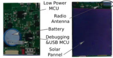
commu-nications involving GreenNet nodes (Fig. 1) developed by STMicroelectronics [2]. The board is based on a System on Chip STM32L low power microcontroller with a test-chip RF200 radio and a ceramic RainSun antenna [3].
Radio Antenna Solar Pannel Battery Low Power MCU Debugging &USB MCU
Figure 1: GreenNet board
II. CHANNEL DIVERSITY OF802.15.4IN THE2.4GHZ
ISMBAND
In presence of two propagation paths, the coherence band
Bc is the frequency shift for which the phase difference at the
receiver changes by 180°. It is a function solely of δd, the path
length difference between the two propagation paths:
Bc=
C
2 · δd
[4]. This expression is only relevant for a pair of paths with similar incident power at the receiver: in fact, if the difference is of the same order of magnitude as the shortest path length, then free space attenuation lessens the impact of the secondary path.
Consequently, the coherence band for short distances is inherently larger than the band for longer distances, where
larger δd corresponds to similar received powers on the
con-sidered paths. For instance, with 1m between the sender and the receiver, a reflection on a wall 1m behind the receiver
reaches the receiving antenna with a power at most one 9th of
the power on the direct path, so it will not hurt much the direct path wave. Conversely, at e.g. 5m or more, the reflected signal may mostly cancel out the direct wave [5]. When the sender and the receiver are further and further apart, the coherence band eventually shrinks well below 0.1MHz at distances of the order of 1km [6].
For δd= 1m (think of a reflection on a wall 50cm behind
the sender or the receiver) the coherence band is 150MHz, or 30 times the 802.15.4 channel spacing (5MHz), whereas the ISM band is “only” 80MHz wide. In this case, the whole range of the available transmission frequencies is too small to exploit the diversity from varying multipath recombinations. From this simple analysis, it appears unlikely that a frequency shift by 5MHz brings any change due to multipath fading at a short distance. The next section considers a more complex synthetic model that captures with more accuracy how the combination of multiple radio waves changes with the channel center frequency.
Multipath RSSI variation (dB) Count −20 −10 0 10 20 0 15000
Multipath with skewed gains
RSSI variation (dB) Count −20 −10 0 10 20 0 10000 (a) Channel 15 to 11 −− Near RSSI variation (dB) Count −20 −10 0 10 20 0 10 20 30 40 (b)
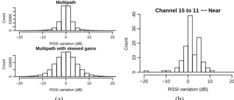
Figure 2: Fig. 2a: Computed RSSI variations at 1m with one dominant path, when changing the frequency by 20MHz (4 channels or a 0.8% wavelength variation). Top: variations solely due to the phase changes at the receiver; bottom: with additional random gain changes among the paths; Fig. 2b: Experimentally measured RSSI variations at 1m
A. Considering more than two propagation paths
With more paths, the recombination at the receiver is harder to predict but, in general, it is expected that the coherence band shrinks. To assess the influence of a channel change, we consider a simple model with one direct (dominant) path and several scatterers or reflectors (for a total of 8 waves, in this section) placed at random positions from the immediate vicinity of the sender or the receiver up to 600% of the direct path length. Each path receives varying amounts of power, and all paths except the direct one, are attenuated by 3dB, which is rather typical for a reflected wave [7]. The histograms of the gain variations for a direct path of 1m appear in Figure 2a, respectively, for a frequency shift of 4 channel spacing gaps (20MHz). Multipath propagation is only modeled for the top histogram, whereas random gain variations of up to 5dB at the sender and the receiver are applied for the bottom histogram. At 1m, much like previously experienced at a few meters in the 433MHz band [8], we do not expect that changing frequency would have much effect: accordingly, there is hardly any gain variation above 6dB in the histogram at the top in Fig-ure 2a. However, FigFig-ure 2b shows a different behavior: at 1m indoors, gain changes of 6 dB or above are common. So, there is something more: in the model, we need to randomly change the channel gains over the various paths by e.g. 5 dB at the sender and the receiver when shifting the channel frequency to get gain variations reaching this magnitude, in the histogram at the bottom of Figure 2a. This last gain distribution significantly differs from the measurements presented in Figure 2b: in the real world conditions, a frequency change does not change the gains randomly, but there is a general improvement when going from channel 15 to 11, with some exceptions.
Our point is that multipath fading is insufficient by itself to explain these gain variations when changing channels. In the next section, we consider the case with a single path to get insight into another possible cause for the gain variations.
III. OUTDOOR MEASUREMENTS:RADIATION PATTERNS
vs.THE TRANSMISSION FREQUENCY
The experiment takes place at a large empty parking lot with the receiver node in the middle, one meter above the ground and the sender on a robot that circles around the receiver. The constant distance between the two nodes is maintained using a string between the center of the circle and
0 0.71 1.41 2.12 2.83 3.53 4.24 4.95 5.65 −100 −90 −80 −70 −60 ch26 ch18 ch11
(a) receiver placed flat (horizontal antenna) 0 0.71 1.41 2.12 2.83 3.53 4.24 4.95 5.65 −100 −90 −80 −70 −60 ch26 ch18 ch11
(b) receiver placed vertically (horizontal antenna) 0 0.71 1.41 2.12 2.83 3.53 4.24 4.95 5.65 −100 −90 −80 −70 −60 ch26 ch18 ch11
(c) receiver placed horizon-tally
(vertical antenna) Figure 3: Reception patterns for a GreenNet board
the robot. Each experiment corresponds to a different position of the sender (flat, vertical pointing up and then, laterally).
Fig. 3 shows the average RSSI (Received Signal Strength Indicator) for 20 packets/channel at each robot position. We can observe that the signal strength notably varies with the aspect angle. The pattern in Figure 3b is expected—it cor-responds to a typical dipole radiation pattern. What is less expected, though, is the difference of up to 10dB from one channel to another in many directions. Furthermore, channel 11 has a higher signal reception strength in many, but not all, directions, which matches the bias already noticed at a short range in Figure 2b.
A. Origin of the phenomenon
We consider a board that integrates the antenna, the circuit board, and a solar panel. So, the transmitted radio signal is in fact the combination of the antenna radiation with the radio waves scattered and reflected by the other components, which is unavoidable. Even with a single path in the environment, the receiver gets a combination of waves from the transmitter, and actually creates itself a set of secondary radio waves. It turns out that the combination of scattered waves is sensitive to the transmission frequency at the granularity of the 802.15.4 channel spacing.
If this effect is better understood, and taking for granted that advanced sensor network MAC layer will include some form of channel agility, one can imagine designing a sensor board in such a way that the difference from one channel to the next is exacerbated, to increase the diversity.
IV. INDOOR MEASUREMENTS
In this experiment, the sender is static and the receiver is attached to a small robot. The sender sends three groups of packets on different channels (11, 18, 26) and the receiver sends back statistics. Then, the sender commands the robot to move forward etc. In the first part of the experiment, nodes are in line of sight, whereas after four meters, they are not in the direct view any more, as the robot moves out of the room. In each position, the sender sends 20 packets on each of the three channels (so 60 packets/position) and waits for the receiver to send back the RSSI measured for each received packet. The emission power is set to 0dbm and there is no retransmission when the hardware acknowledgement is not received.
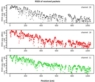
Figure 4a shows the RSSI measured on each channel over the 10m course of the robot. The RSSI follows a general trend: it goes down as the robot moves away. Nevertheless,
RSSI of received packets Position (cm) ● ●●● ●●●● ● ● ● ● ●●● ● ● ●● ● ●●● ● ● ●●●●● ●●●●●●●●●● ● ●●●● ● ●● ● ● ● ● ● ● ●●●●●●●●● ● ● ●● ●●●● ● ● ● ● ●●● ● ● ● ● ● ● ● ● ● ● ● ●●●●● ● ● ● ● ● ● ● ● ● ● ● ●● ● ● ● ●●● ● ● ● ● ● ●●●●●● ● ● ● ● ● ● ● ● ● ● ●●●● ● ● ● ● ● ● ● ● ● ● ● ● ● ● ● ● ● ●● ● ● ● ● ● ● ● ● ● ● ● ● ●● ● ● ● ●● ● ●●●● ● ●●● ● ● ● ● ● ● ● ● ●● ● ● ● ● ● ● ● ● ● ● ● ●●●● ● ● ● ● ●● ● ● ● ●● ●● ● ● ● ●● ● ●●●●● ● ● ● ●● ● ● ● ● ● ● ●● ● ● ● ●●●● ● ● ●●● ● ● ● ● ● ● ● ●●●●●●●●● ● ● ● ● ● ● ● ● ● ● ● ● ● ●●●●●● ● ● ● ● ● ● ● ●●●●●●●●●●●●●●● ● ● ● ● ● ● ●●● ● ● ● ● ● ● ● ● ● ● ●● ● ● ● ● ● ●●● ● ● ● ● ● ●● ● ● ● ● ● ● ●● ● ●●● ● ● ● ● ● ● ● ● ●● ●● ● ● ● ● ●●● ● ● ●●●●● ● ● ● ● ● ● ● ● ● ● ● ● ● ● ●● ●● ● ● ● ● ● ● ●● ● ● ● ● ● ● ● ● ● ● ● ● ● ● ● ● ● ●●● ● ● ● ● ● ●● ● ● ● ●● ● ● ● ● ●● ● ● ● ● ●●●●● ● ● ● ● ● ● ● ●●● ●●●● ● ●●● ● ● ● ● ● ●●●● ● ●● ● ●● ● ●● ●● ● ●●● ● ● ● ● ● ● ● ● ● ● ● ●●● ●●●● ● ● ● ● ● ● ● ● ● ● ● ● ●●● ● ● ● ● ● ● ● ● ● ● ●● ● ● ● ●● ● ●● ● ●●● ● ● ●● ● ● ● ● ● ● ● ● ● ● ● ● ● ● ● ● ● ● ● ● ● ● ● ● ● ● ● ● ● ●● ●● ● ● ● ● ● ● ● ● ● ● ● ● ● ● ● ● ●● ● ● ● ● ● ● ● ● ●●●● ● ●● ● ●● ● ● ● ● ● ● ● ●● ● ● ● ● ● ● ● ● ● ●● ● ●● 0 200 400 600 800 1000 −115 −100 −85 RSSI a vg. (dBm) channel 26 0 200 400 600 800 1000 −115 −100 −85 RSSI a vg. (dBm) channel 18 0 200 400 600 800 1000 −115 −100 −85 RSSI a vg. (dBm) channel 11
(a) RSSI value for each position for channels 11, 18, 26 Figure 4: Indoor evaluation
locally, the RSSI varies considerably even when the sender and the receiver are in the same room, and clearly differs from one channel to another: signal fadings on each channel are rather uncorrelated although the measurements were taken at very near instants. Obviously, in the same room, RSSI is high enough to warrant successful reception, whereas it gets more challenging at the other end of the corridor.
V. RELATED WORK
Watteyne et al. [4] considers that deep fading caused by destructive interference can be overcome by switching the frequency or the location of a node. They estimate that the coherence band for 2.4GHz varies from 5MHz for long ranges up to 15MHz for extremely short links, and we suspect that this finding is also due to the physical configuration of the sender and receiver used in experiments.
In the experiments made by Varela and Sánchez [9], they find that the 90% coherence band is of the order of 5 to 10MHz at 10m, and 10MHz or above at 3m. This coherence
band corresponds to B0.9 = 50σ1τ, where στ is the mean
delay among the paths weighted by the received power, which results in 50MHz and more for the 50% coherence band (3dB
variation) (B0.5 = 5σ1
τ). This value is much larger than what
we observe with our nodes. Besides, they also set out that the coherence band is generally larger for the copolar component than for crosspolar one whereas in most other studies, only the copolar antenna positions are considered. This is not surprising as the crosspolar setup reduces the gain on the direct path.
Wysocki and Zepernick [10] presented a characterization of the indoor radio propagation in the 2.4 GHz band with measurements of fading characteristics, multipath parameters, and background interference. In a room of 10m by 8m, they find lower coherence bands than Varela, which may be due to an environment that contains many scatterers.
Giorgetti et al. [11] proposed an approach based on di-rectional antennas placed on different sides of a node, using specific 802.15.4 antennas. This solution can be used to overcome the imperfection of a board with a ceramic antenna, but the main drawback is the size of the device—GreenNet nodes are only 4 mm thick.
VI. CONCLUSIONS
In this paper, we have provided an experimental evidence of the fact that changing channels can have a significant influence on the radio propagation and consequently, on the quality of the link between two or more devices. However, in the case of close range communications in line of sight, channel diversity is not only due to multipath, but also to other phenomena. It is hard to believe that just multipath fading can have an impact of up to 10dB when changing channels in line of sight at a short distance. We postulate that the difference most probably comes from the board construction. As the antenna interferes with the board, its ground plane and, in our case, the solar panel, it strongly affects the radiation pattern and renders it sensitive to the transmission frequency.
This fact may become an issue for the basic 802.15.4 scheme that do not support channel hopping. In this case, nodes need to be laid out with a comfortable range margin to compensate for the channel gain uncertainty. Even with stable omnidirectional antennas and a copolar placement of nodes, multipath fading is unavoidable, and may only be overcome with antenna diversity, which in turn imposes a much larger footprint. On the contrary, 802.15.4 channel hopping schemes may significantly benefit from the gain variability with respect to the transmission channel, so we can actually design boards to increase the level of diversity.
REFERENCES
[1] 802.15.4e-2012: IEEE Standard for Local and metropolitan area
networks–Part 15.4: Low-Rate Wireless Personal Area Networks (LR-WPANs) Amendment 1: MAC sublayer, IEEE Std., 16 April 2012.
[2] L.-O. Varga, G. Romaniello, M. Vucinic, M. Favre, A. Banciu,
R. Guizzetti, C. Planat, P. Urard, M. Heusse, F. Rousseau, O. Alphand, E. Duble, and A. Duda, “Greennet: An energy-harvesting ip-enabled wireless sensor network,” Internet of Things Journal, IEEE, vol. 2, no. 5, pp. 412–426, Oct 2015.
[3] “RainSun.” [Online]. Available: http://www.rainsun.com
[4] T. Watteyne, S. Lanzisera, A. Mehta, and K. Pister, “Mitigating Multi-path Fading through Channel Hopping in Wireless Sensor Networks,” in Communications (ICC), 2010 IEEE International Conference on, May 2010, pp. 1–5.
[5] D. Sexton, M. Mahony, M. Lapinski, and J. Werb, “Radio channel
quality in industrial wireless sensor networks,” in Sensors for Industry Conference, 2005, Feb 2005, pp. 88–94.
[6] D. C. Cox and R. P. Leck, “Correlation Bandwidth and Delay Spread
Multipath Propagation Statistics for 910-MHz Urban Mobile Radio Channels,” Communications, IEEE Transactions on, vol. 23, no. 11, pp. 1271–1280, 1975.
[7] O. Landron, M. Feuerstein, and T. Rappaport, “A comparison of
theoretical and empirical reflection coefficients for typical exterior wall surfaces in a mobile radio environment,” Antennas and Propagation, IEEE Transactions on, vol. 44, no. 3, pp. 341–351, Mar 1996. [8] P. Tuset-Peiró, A. Anglès-Vazquez, J. López-Vicario, and X.
Vilajosana-Guillén, “On the suitability of the 433 mhz band for m2m low-power wireless communications: propagation aspects,” Transactions on Emerging Telecommunications Technologies, vol. 25, no. 12, pp. 1154– 1168, 2014. [Online]. Available: http://dx.doi.org/10.1002/ett.2672
[9] M. S. Varela and M. G. Sánchez, “RMS Delay and Coherence
Band-width Measurements in Indoor Radio Channels in the UHF Band,” Vehicular Technology, IEEE Transactions on, vol. 50, no. 2, pp. 515– 525, 2001.
[10] T. A. Wysocki and H.-J. Zepernick, “Characterization of the Indoor
Radio Propagation Channel at 2.4 GHz,” Journal of telecommunications and information technology, pp. 84–90, 2000.
[11] G. Giorgetti, A. Cidronali, S. K. Gupta, and G. Manes, “Exploiting Low-Cost Directional Antennas in 2.4 GHz IEEE 802.15.4 Wireless Sensor Networks,” in Wireless Technologies, 2007 European Conference on. IEEE, 2007, pp. 217–220.