Developing & Applying a Miniaturized Active
Microchip Device
ARCHIVES
By Byron C. Masi
B.S. Chemical & Biomolecular Engineering Johns Hopkins University, 2007
AS SACHUSETTS INSTRTUE
JUL
RAR2E
IES
Submitted to the Department of Chemical Engineering in Partial Fulfillment of the Requirements for the Degree of
Doctor of Philosophy in Chemical Engineering at the
Massachusetts Institute of Technology June 2012
© Massachusetts Institute of Technology All rights reserved
Signature of Author... ...
Byron C. Masi Department of Chemical Engineering April 18th 2012 C e rtifie d b y ... Robert S. Langer Institute Professor 'v A esis e5 or C e rtifie d b y ... 4richael J. Cima Professor of Material Science and Engineering Thesis Supervisor A ccepted by ... ... . . ... . . ...
Patrick S. Doyle Professor of Chemical Engineering Chairman, Committee for Graduate Students
Developing & Applying a Miniaturized Active Microchip Device By
Byron C. Masi
Submitted to the Department of Chemical Engineering
On April 18th, 2012 in partial fulfillment of the requirements for the degree of Doctor of Philosophy in Chemical Engineering
ABSTRACT
Glioblastoma multiforme (GBM) is the most common and aggressive malignant brain tumor. Treatment of GBM is a daunting task with median survival just at 21 months. Methods of localized delivery have achieved moderate success in treating GBM. Depot devices have been limited due to the relatively narrow drug distribution profile they achieve. Convection enhanced delivery has demonstrated that broad distribution is key, but is limited due to uncertain spatial distribution and serious side effects. Miniaturized depot devices, implanted into the tissue surrounding the tumor resection site, could achieve a broad aggregate distribution profile. The capabilities of localized delivery can be enhanced by utilizing mircoelectromechanical systems (MEMS) technology to deliver drugs with precise temporal control over release kinetics. An intracranial MEMS based device was developed to deliver the clinically utilized chemotherapeutic temozolomide (TMZ) in a 9L rodent glioma model. An activation mechanism based on thermally induced membrane failure was developed and incorporated. The kinetics of TMZ release were validated and quantified in vitro. The safety of implanting the device intracranially was confirmed. The impact of TMZ release kinetics on survival was investigated by comparing the effects of drug release rates and timing. TMZ delivered from the device prolonged animal survival. The results from the in vivo efficacy studies indicate that early, rapid delivery of TMZ from the device results in the most prolonged animal survival. This miniaturized MEMS device holds tremendous potential for the treatment of GBM and related diseases. Circuit diseases are neurological disorders that arise from the dynamic miscommunication within a neural circuit. Anxiety, mood disorders, and the chronic effects of traumatic brain injury (e.g. Parkinsonism) are prevalent, and are circuit diseases. Circuit diseases could be clinically addressed by a technology capable of electrical, and chemical neuro-modulation. A catheter based device capable of simultaneous infusion of multiple fluids and electrical stimulation was designed and fabricated. Preliminary in vitro infusion studies indicate that the reliable and reproducible infusion of multiple fluids is possible. Future work will focus on improving the biocompatibility of the device and studying the performance of the device in non-human primate models of neurological disorders.
Thesis Supervisors: Professor Michael J. Cima (MIT)
Institute Professor Robert S. Langer (MIT) Thesis Committee: Professor Paula T. Hammond (MIT)
Dr. John T. Santini, Jr. (On Demand Therapeutics, Inc.)
Acknowledgements
Michael, you have taught me many lessons throughout the past 5 years, many of which will remain with me for the rest of my life. Your influence has made me a better researcher and thinker. Despite your busiest schedules you always make time for your students and never cease to have insightful and instructive input. Thank you for mentoring me throughout my time here.
Bob, I'd like to thank you for your never ending enthusiasm and support throughout my time here. It has been an inspiration to work with you.
I would like to thank my thesis committee members John Santini and Paula Hammond for their time, attention and guidance. Paula, you are consummately positive and motivating. Thank you for being a part of my thesis. John, you have been tremendously generous with your time and advice. Even when you moved to another state, you never ceased to be available for phone calls and meetings. Thank you for your guidance and words of wisdom.
I would like to thank the members of the Cima lab, past and present, for their influence and camaraderie. Karen, Grace, Heejin, Irene, Yibo, Yoda, Qunya, Maple, Vincent, Syed, Lenny, Dan, Joan, Agata, Kevin, Negar, Jen, Anna R., Anna T., Yuan, Ollie, Matt, Laura and Jay, you have all made for a rich, fun and welcoming group. Alex, thank you for working with me throughout the early years. It was great to have a companion in putting together all those early slide decks and figuring how on earth an 'HPLC' works. Hong Linh and Noel, I would like to especially thank you two for being so helpful and giving with your expertise in MEMS and device manufacturing. You both made my transition into an unfamiliar field very smooth, and relatively painless. I wish you both the best with all your endeavors and growing families.
Very special thanks are reserved for Chris and Urvashi. Urvashi, your enthusiasm, humor, support and astonishing intellect were crucial to my perseverance during the middle years of my thesis. Thank you for guiding, and bolstering me throughout your time here. Chris, you are one of the most remarkable people I have ever met. Your intellect, wit, patience and mentorship have influenced me in countless ways. Thank you for the discussions and pep-talks when my experiments weren't going well, and thank you for the constant good company and humor. Steve, Justin, Josh and Adel: You were all a constant source of support, laughs and fond memories. You're all the reason I survived our first year, and my time here at MIT was better for having you four as close friends.
Mom, Dad, Dylan and Elizabeth: you have all helped make me the person I am today. Thank you for your support during the hard times, enthusiasm during the successful times, and your unerring advice throughout. You should all take pride in this document and the work it describes. It would not have been possible without you.
Liz, you have been my most significant source of support and inspiration throughout my Ph.D. You are one of the most thoughtful, enthusiastic, supportive, and sage people I have ever met. Your strength, infectious work ethic, and dedication have bettered me in many ways. You have made the last several years very special, and meeting you is the most significant event of my time here at MIT.
Table of Contents
List o f F ig u re s ... 8
List o f T a b le s ... 1 3 1. Introduction ... 14
1.1 M otivation...14
1.2 Problem Statem ent...14
1.2.1 Methods of Local Delivery: Convection Enhanced Delivery & Depot Devices ... 14
1.3 M iniaturized depot devices for im proved therapy ... 17
1.3.1 M icro-Electrical-M echanical-System s Based Depot Devices ... 18
1.4 Thesis Objectives...21
1 .5 C o n c lu sio n ... 2 2 2. Device Design ... 23
2 .1 . M ic ro c h ip ... 2 3 2.1.1 Chip Release Kinetics ... 23
2.1.2 Device Activation M echanism : A New Approach ... 27
2.1.3 Energy Transm ission: Reducing Overall Device Invasiveness ... 29
2 .2 R e se rv o ir ... 3 1 2.2.1 M aterial Selection ... 31
2.2.2 Reservoir Architecture ... 31
2.3 Activation Hardware ... 33
3 . M e th o d s ... 3 5 3.1. Clean room fabrication techniques... 35
3.1.1 Fuse Study Devices... 35
3.1.2 Three m em brane devices ... 36
3.2 TM Z analytics (HPLC)... 37
3.2.1 High Pressure Liquid Chrom atography ... 37
3 .2 .2 S ta b ility ... 3 7 3.2.3 Solubility... 38
3.3.1 Fuse Study Devices... 38
3.3.2 T M Z Devices ... 39
3.4 Device Assem bly ... 39
3.5 Release procedures...40
3.6 In vivo Studies ... 40
3.6.1 Biocom patibility study ... 41
3.6.2 Efficacy Studies...41
3.7 Im m unohistological analyses...42
4. Fuse Activation M echanism ... 43
4.1 Device M anufacture... 43
4.2 Activation Experim ents...45
4.2.180 pm mem branes...45
4.2.2 300 pm m em branes ... 51
4.3 Release Experiments...52
4.4 M echanism Discussion ... 53
4 .5 C o n c lu sio n ... 5 6 5. In Vitro Characterization of Device Perfom ance... 57
5.1 T M Z Form ulation ... 57
5.1.1 Packaging in C02...57
5.1.2 Co-Form ulation of TMZ and ... 59
5.2 In vitro Release Studies ... 63
5 .3 C o n c lu sio n ... 6 7 6. In Vivo Studies...69
6.1 Pilot in vivo studies ... 69
6.1.1 Potential toxicity and potential side effects ... 69
6.1.2 Prelim inary survival studies ... 71
6.2 Large scal e in vivo ... 73
6.2.1 Effect of TMZ delivery rate on efficacy... 73
6.2.2 Effect of TMZ delivery time on efficacy ... 74
6.2.3 Com parison of the device to a polym er-based delivery system ... 75
6.2.4 Im m unohistological analyses... 76 6
6.3 Discussion of in vivo results ... 78
6.3.1 Prelim inary in vivo studies ... 78
6.3.2 Efficacy Studies ... 78
6.3.3 Im m unohistological analyses... 80
6.4 Conclusions ... 81
7. Future W ork... 8 2 7.1 Co-delivery of synergistic m olecules for the treatm ent of G BM ... 82
7.1.2 Prelim inary tw o com partm ent device work ... 84
7.1.3 Im pact of drug release kinetics on in vivo efficacy studies... 86
7.2 Investigation of m ass transfer m echanism s in depot devices ... 87
7.2.1 Varying Orifice Size and Num ber ... 88
7.2.2 Changing the Drug Payload ... 89
7.2.3 Including Excipient ... 90
7.2.4 Plausible m echanism s and directions of further research... 91
8. A new device: The 'Injectrode'... 92
8.1 Circuit Diseases ... 93
8.2 Clinical Rationale: Traum atic Brain Injury, Anxiety and M ood Disorders ... 94
8.2.1 Intractable Anxiety and M ood Disorders... 94
8.2.2 Traum atic Brain Injury and Associated Chronic Neurological Disorders ... 95
8.3 Device Design and M anufacture... 96
8.3.1 The Prior Art for M icro-cannula Devices... 96
8.3.2 The First Generation Injectrode ... 98
8.4 In Vitro Infusion Results ... 100
8.5 Future steps in the developm ent of this device ... 103
8.5.1 In vitro tissue phantom infusion studies... 103
8.5.2 Device Coating for Structural Integrity and Biocom patibility ... 104
8.5.3 In vivo experim entation to confirm neural circuit and behavior m odification ... 106
8.6 Conclusion...107
List of Figures
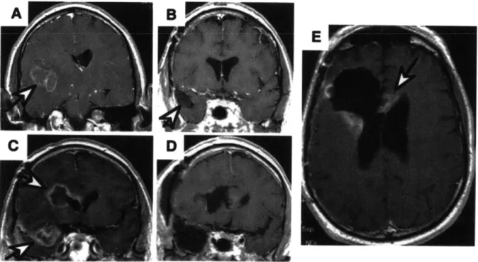
Figure 1.1 MRI images of a GBM patient. A coronal MRI image depicting a GBM lesion (indicated by the white arrow) (A). Post resection surgery MRI depicting the void (white arrow) left by the procedure (B). MRI image showing the same patient 6 months after resection surgery, full chemotherapeutic, and radiation therapy regimen. Two recurrent lesions are indicated by white arrows (C). Image post second resection surgery showing two resection sites (D). Scan 3 months after second resection surgery depicting recurrent lesions at the immediate periphery of the resection site (E). Image from Deorah et al. 15 Figure 1.2 Diagram of the envisioned device implementation. The primary tumor burden is removed, to the extent possible, by surgical resection. Infiltrative neoplastic cells (cartooned here as the black shaded region surrounding the resection site) remain, and are free to proliferate unless addressed by radiation and/or chemotherapy. Devices can be
packed within the resection site (not shown here for simplicity) and implanted into the tissue immediately surrounding the resection site. Upon device activation the aggregate release profile of many diffusion driven devices could be equivalent to the pressure driven release profile of CED and hopefully address the majority of remaining glioma cells. 18 Figure 1.3 Schematic of the original MEMS based micro-chip drug delivery device
developed by John Santini, Ph.D.. In this manifestation the drug (active substance) is loaded into micro-machined pyramidal reservoirs that are each capped by a gold membrane. Activation induces the electrochemical dissolution (formation of gold chloride)
of the anode (membrane). Figure from Santini et al. 20
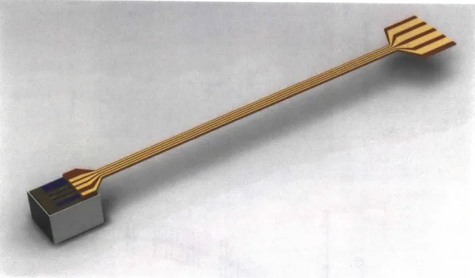
Figure 2.1 A CAD rendering of the active device in its current form. A liquid crystalline polymer reservoir (gray) is capped by a silicon chip (purple and gold) that contains 3 nitride membranes (green). Energy is delivered to the device via polyimide coated copper leads
(brown and gold). 23
Figure 2.2 Survival plots and in vitro release kinetics for the TMZ laden polymer study conducted by Brem et al. Survival is depicted as the percentage of animals still alive within a group as a function of time. Both polymer wafer groups displayed improved
median survival and number of long term survivors (animals surviving until the protocol mandated stop date) when compared to oral treatment and control groups. Figure copied from Brem et al. (A) The release kinetics of TMZ are first order and result in a final delivery
of approximately 70% of wafer payload in 75 hours. (B) 24
Figure 2.3 Sketch of the assumed spatial concentration profile as drug releases from the device. The reservoir is assumed to be at saturation, Co. The exterior of the device is assumed to be at infinite sink conditions, Ci = 0 mg/ml. Steady state, uni-directional
diffusion is assumed, allowing the gradient in Fick's first law to be one dimensionalized (Eq.
2) and linearized (Eq. 3). 25
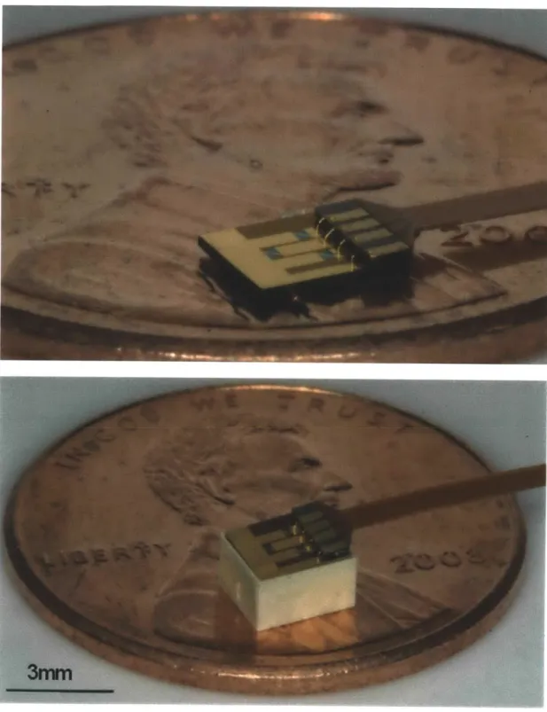
Figure 2.4 Color photographs of the chip:lead assembly (A) and entire device and on a United States penny (B). A close up photograph of the chip:lead assembly. Gold wire bonds are visible between the gold coated copper pads of the flexible PCB and the patterned gold on the chip (A). Photograph of the fully assembled device. The chip rests on the internal shoulder of the reservoir, leaving a small space for the UV curable epoxy to wet into and be
cured within. 30
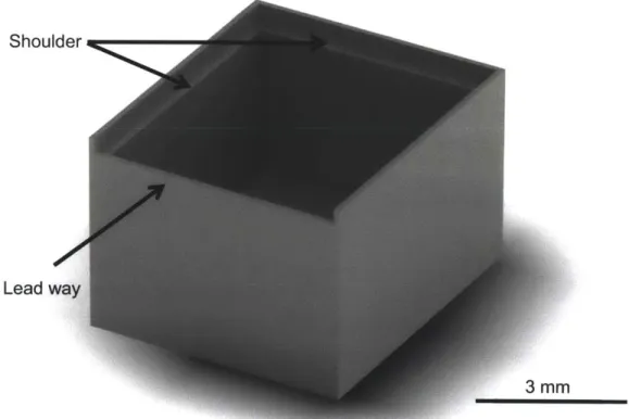
Figure 2.5 CAD rendering of the injection molded liquid crystalline polymer reservoir. The reservoir dimensions are 3.7 by 3.2 x 2.2 mm. The total drug payload is 10 milligrams of TMZ. The 200 pm shelf is visible on the interior face of the reservoir walls. This shelf serves a seat for the chip and as an upper boundary for drug during the loading process. A lead-way was designed in the top perimeter of the chip to allow the polyimide leads to
project out from the device. 32
Figure 2.6 Circuit diagram for the activation hardware. The switchbox (dashed box) contains a matching resistor, shunt resistor and a single pole, triple throw switch. The head piece contains each membrane on independent, parallel circuits. The matching resistor allows the voltage source to be impedance matched to the load. The shunt resistor and membrane are in parallel such that, when the membrane ruptures, current is directed through the shunt
resistor. 34
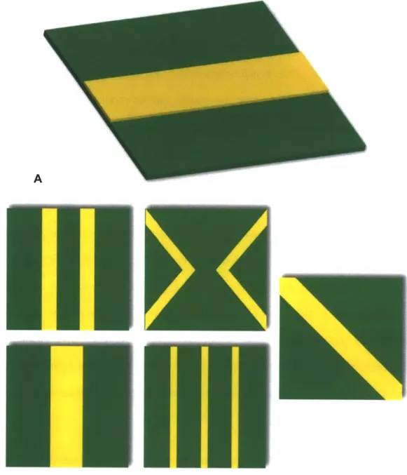
Figure 3.1 Fabrication process sequence for creating nitride membranes in the microchip. 36 Figure 4.1 Digital renderings of the suspended nitride membranes and overlying fuses. A. Simple rectangular fuses (yellow) were deposited over the nitride (green) membrane in the small membrane study. B. More intricate fuse geometries were studied in the large, 300 pm, membrane devices. Two 20 pm fuses, one 40 pm fuse, two 40 pm 'v' shaped fuses,
three 10 pm fuses, and one 40 pm diagonal fuse. 44
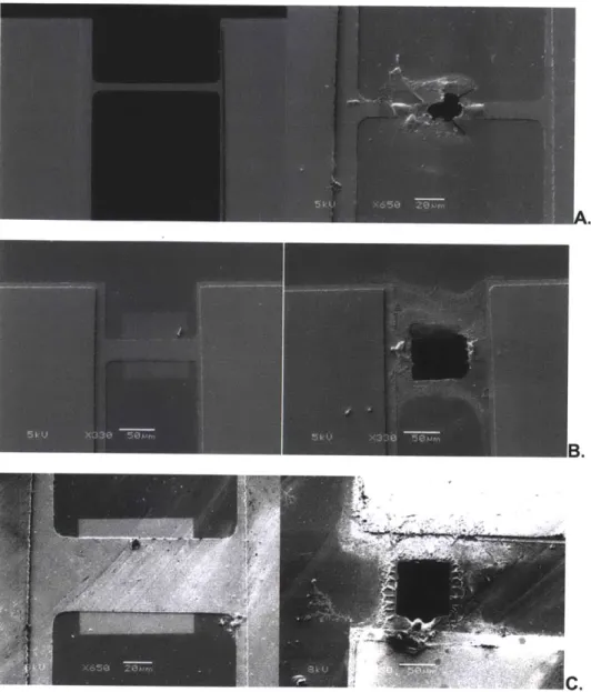
Figure 4.2 SEM microscope images showing the structure before and after activation for each fuse width (250 nm Au layer). A. 20 pm wide. B. 40 pm wide fuse. C. 60 pm wide. 47 Figure 4.3 Confocal microscope images for 250 nm thick fuses. A. 20 pm wide. B. 40 pm
wide. C. 60 pm wide. 48
Figure 4.4 Oscilloscope capturing images showing activation pulse voltage values (blue) and current (red) values for 250 nm thick fuses. A. 2 pm wide. B. 40 pm wide. C. 60 pm
Figure 4.5 Minimum energy to burst fuse as a function of fuse dimensions. Please refer to
Table 4.1 for values. 50
Figure 4.6 Light microscope images of ruptured 300 pm membranes. A. Membranes ruptured via x fuses. B. Membranes ruptured via diagonal fuses. 51 Figure 4.7 In vitro release profiles, n = 5, for activated devices, n = 5 for control devices.
Error bars represent standard deviation. 53
Figure 4.8 FEA Analysis of the suspended structure showing an isometric view of the Von Misses stress on the surface area of the membrane, and a lateral view for displacement showing structural deformation. The mesh of the analysis included approximately 10E5 elements. A. 20 pm wide fuse (B), 40 pm wide fuse (C), 60 pm wide
fuse (D). 54
Figure 5.1 An example of inconsistent release profiles that result from packaging in C02. The rate of release was consistent across the three devices and compares well to the theoretical release. The onset of release and overall extent of release vary greatly across the 3 devices. The theoretical line is based on zero order approximations of the release rate utilizing Fick's first law. The controls demonstrate excellent sealing and drug retention
throughout the time scale for release. 58
Figure 5.2 Renders of the device in the three stages of assembly. A. An empty reservoir. The shoulder that the chip must rest on is visible around the interior perimeter of the reservoir. B. A filled reservoir. Drug and any excipients must be loaded into the device without accumulating on the shoulder in order to ensure proper alignment during subsequent assembly steps. C. An assembled device. The chip is placed in the reservoir, resting on the shoulder. Biomedical grade epoxy is then used to secure the chip to the
reservoir and seal the reservoir. 60
Figure 5.3 A series of color photogrpahs depicting the steps in device filling. An empty reservoir is placed in a fixture that allows a pre-weighed amount of drug to be added up the the level of the shoulder (A). Drug is loaded into the reservoir and partially compacted to create a small well within the drug powder. This well allows molten PEG to be added to the reservoir (B). After typically three repititions, the majority of the air has been displaced from the TMZ powder and replaced by PEG. The vacuum fixture ensures that TMZ and PEG do not escape the reservoir or accumulate on the shoulder (C). 61 Figure 5.4 Schematic of the vacuum co-formulation process. The vacuum fixture clamps a
high air permeability Teflon AF membrane over the surface of the PEG:TMZ mixture. The PEG:TMZ mixture is trapped within the reservoir, but any air is free to flux out when a vacuum is pulled. Once the air is removed, PEG is free to wet within the interstices of the
TMZ powder. 62
Figure 5.5 Release curves for TMZ filled devices releasing into 370C water. Devices (n=3) with 3, 2, 1 or 0 membranes activated were placed in agitated baths and sampled for TMZ content. The errors bars are the standard error. Release is a function of the number of activated membranes and release does not occur unless the device is activated. 63 Figure 6.1 Graphical presentation of normalized animal weight as a function of time. All animals displayed minimal weight loss during the acute phase and animal 5 displayed
robust weight gain over the chronic time scale. 70
Figure 6.2 Survival curves for the preliminary efficacy trial. Animals with activated devices demonstrated the most prolonged survival. Un-activated devices had an identical impact on animal survival as no treatment at all. Animals receiving aCSF had a slightly shorter
median survival than no treatment. 72
Figure 6.3 Impact of drug release rate on survival. Animals that received activated devices on day 0 had median survivals of 40 (42.8 % LTS), 28 (28.5 % LTS), and 21 (12.5 % LTS) days for 3, 2, and 1 membranes activated respectively. 73 Figure 6.4 Impact of drug release time on survival. Animals that had all 3 membranes activated day 0, 3, or 5 had median survivals of 40 (42.8 % LTS), 24 (12.5 % LTS) and 23 days. 74 Figure 6.5 Comparison between microchip and polymer-based delivery methods. Those animals
that received two TMZ:polymer wafers on day 5 had a median survival of 34 days, while those that had all 3 membranes opened on day 5 had median survival of 23 days. 75 Figure 6.6 Immunohistological results of Ki67 and caspace-3 staining. (A) Ki67 positive cells are green and cell nuclei are blue. Each panel is a representative image from each efficacy study group. The 3MOD (3 membranes activated on day 0) panel contains the fewest number of Ki67 positive cells. (B) Quantitative results obtained by averaging 3 representative images from each group. The two longest surviving groups, wafer and 3MOD, have the lowest levels of Ki67 positive cells. (C) Caspase-3 positive cells are green and cell nuclei are blue. Each panel is a representative image from each efficacy study group. (D) Quantitative results obtained by averaging 3 representative images from each group. The 3MOD (3 membranes activated on day 0) panel contains the second highest
number of caspace-3 positive cells. 77
Figure 7.1 CAD renderings of cross sectional views of the proposed two compartment device. The reservoir architecture is essentially the same as the single compartment device only mirrored around and internal plane. Each reservoir can be capped by the normal chip without any alteration to the chip design or manufacturing. 84
Figure 7.2 Release of TMZ from a two compartment reservoir device. Each compartment was loaded with 5 milligrams of TMZ and co-formulated with PEG. The first chip had 3 membranes activated at t = 0 hours and the second chip was activated at t = 162 hours. 85 Figure 8.1 Digital renders and SEM images of the core components of the injectrode. A CAD rendering of the manifold. Four ports are visible. The port on the circular face is a through hole through with the introducing needle and glass tube are threaded. The center port on the cylinder surface is for filling the epoxy chamber (panel B). Pump tubing is inserted into the remain two ports which service the infusion chambers (Panel B)( A). A cross sectional view of the manifold depicting the epoxy chamber, two infusion chambers, and the silicone septa (blue) (B). CAD rendering of the multi-lumen glass tube. The large lumen (90 pm) houses the electrode. The two small (38pm) lumens conduct fluid from manifold down to the distal tip of the device. Each 38 pm lumen has an access port cut into it to allow for interfacing with the manifold (C). Scanning electron microscopy image of several glass
tubes viewed end on. 99
List of Tables
Table 2.1: Device dimensions for a 10 mg payload ... 27
Table 4.1: Activation energy values depicted in Figure 4.5. n = 5... 48
Table 6.1: Survival data for the preliminary efficacy study ... 71
Table 6.2: Survival data for the large scale efficacy study ... 75
1. Introduction
1.1 Motivation
A glioma is a cancerous tumor arising from the glial cells of the brain. The most common and aggressive form of glioma that afflicts humans is glioblastoma multiforme (GBM) [1]. GBM accounts for 12-15 percent of all primary brain tumors and afflicts 5000 Americans per year [2, 3]. Glioblastoma multiforme is nearly invariably fatal and the average patient will survive between a few months (minimal treatment) and 12 to 18 months (maximal treatment) [4, 5], and those patients surviving 2-3 years are deemed 'long-term survivors'. Deorah et al, concluded that GBM patients have not shown improved survival since the late 1980's based on a study conducted in 2006 of brain cancer incidence and a review of survival rates in the United States from 1973 to 2001 [1]. Glioblastoma multiforme and related gliomas present devastating challenges to patient survival and demand improved treatment modalities.
1.2 Problem Statement
1.2.1 Methods of Local Delivery: Convection Enhanced Delivery & Depot Devices
Current treatment methods generally combine surgical resection (Figure 1.1) of the primary tumor, radiation therapy and a chemotherapeutic regimen [5]. Chemotherapy is most often administered systemically via intravenous injection or oral formulations. One of the major limitations to the development of more effective brain tumor therapies is the presence of the blood-brain barrier, which prohibits the transfer of molecules that are larger than 500 daltons or are non lipid-soluble. The presence of the blood brain barrier causes only a fraction of administered systemic dose to ever reach the brain. To achieve therapeutics levels within the brain, excessive amounts of drug must be administered to account for the poor partitioning, resulting in systemic toxicities. Dosing regimens are frequently designed to remain just under
toxicity thresholds, as opposed to achieving therapeutic tissue concentrations. Limitations in drug exposure and systemic toxicity have spurred on the development of localized delivery methods [6-12].
One method of circumventing the blood brain barrier is to pack the resection site with drug depots which can then release drug into the afflicted tissue in a time-controlled manner. These depot devices have shown promise in treatment, but achieve limited spatial distribution [7, 8, 10, 13-15]. The concern is that the limited distribution of drug leaves wide spread, un-resected, glioma cells unaddressed and free to proliferate (Figure 1.1 C,E) [7]. Efforts have been made to find methods that improve spatial drug distribution.
One method for achieving increased drug distribution is convection-enhanced delivery
Figure 1.1 MRI images of a GBM patient. A coronal MRI image depicting a GBM lesion (indicated by the white arrow) (A). Post resection surgery MRI depicting the void (white arrow) left by the procedure (B). MRI image showing the same patient 6 months after resection surgery, full chemotherapeutic, and radiation therapy regimen. Two recurrent lesions are indicated by white arrows (C). Image post second resection surgery showing two resection sites (D). Scan 3 months after second resection surgery depicting recurrent lesions at the immediate periphery of the resection site (E). Image from Deorah et al.
(CED). A catheter is surgically placed in the target tissue under image guidance during CED. An external pump is then used to infuse drug solution, and to drive subsequent fluid flow in the tissue. CED has been shown to be efficacious both in achieving broad distribution of drug and in retarding tumor progression [6, 7, 9, 12, 16-18]. The results of CED have demonstrated that broad distribution is possible and is in fact critical to improved treatment, but as a treatment modality CED suffers from several considerable drawbacks.
The medical procedure surrounding CED can be extremely inconvenient for the patient. Catheter placement and infusion requires that the skull be immobilized in a stereotaxic device and the catheter must be connected to an external pump and fluid reservoir during infusion. Infusion times in the literature have ranged from hours to weeks and commonly last around 7 days [12, 15].
The greatest issue confronting CED is the uncertainty in fluid flow. The physical parameters and characteristics of the brain greatly dictate the direction of fluid flow. White matter presents less resistance to fluid flow causing the infused fluid to preferentially flow through white matter [7]. The natural structure of the brain can form conduits for fluid flow. These effects are largely unpredictable and unavoidable. Infusion itself changes the tissue properties of the brain. The initial path of fluid flow alters the tissue, for example, by dilating the ECM and causing it to present less resistance to fluid flow. Any subsequent administrations of treatment, therefore, are more likely to follow the same path, possibly leaving portions of diseased tissue completely unaddressed. CED's effect on surrounding tissue is so extensive that it can cause edema that is in many cases indistinguishable from peri-tumoral edema [7]. Edema resulting from the disrupted vasculature of GBM tumors is already one of the leading causes of morbidity in patients [19]. A treatment that exacerbates the level of edema, and therefore morbidity, is severely limited.
The benefits and drawbacks of CED can best be understood in the context of the disease. Glial tumors have been shown to have heterogeneous cellular populations within a given tumor [4, 20, 21]. Two basic and easily defined cohorts are proliferative cells and
migratory cells. The presence of migratory cells is thought to be a leading cause of tumor recurrence [20]. Migratory cells are able to infiltrate healthy tissue surrounding the primary tumor. Their departure from the primary tumor allows them to avoid physical removal by
resection, and therapeutic insult because of the limited drug distribution profile discussed above (Figure 1.1). A large distribution profile, therefore, is necessary for efficient treatment. Migratory cells also tend to follow certain anatomical structures during infiltration [20]. These concepts demonstrate that regional control of delivery of multiple agents is critical to disease treatment.
1.3 Miniaturized depot devices for improved therapy
Improved drug distribution is clearly necessary to improve treatment, but the migratory nature of the disease exposes the fact that regional control of drug delivery is critical. The uncertainty in fluid flow present in CED is unacceptable, but its increased distribution profile is crucial. Depot devices could be employed in such a way as to both achieve an improved distribution and capitalize on disease characteristics. Miniaturized depots could be packed into the resection site as well as injected to a perimeter beyond the resection site (Figure 1.2). The ability to place devices in specific locations facilitates delivery to specific anatomical features while avoiding the uncertainty present in CED. Each device has its own reservoir allowing for regional control of the delivery for each therapeutic. The majority of recurrent lesions occur within 2-3 centimeters of the resection site [5]. Implanting devices within the tissue immediately surrounding the resection site, therefore presents a promising approach to preventing tumor recurrence. The use of miniaturized active devices allows for the heterogeneous nature of the disease to be treated in a comparably heterogeneous fashion.
Figure 1.2 Diagram of the envisioned device implementation. The primary tumor burden is
removed, to the extent possible, by surgical resection. Infiltrative neoplastic cells (cartooned here as the black shaded region surrounding the resection site) remain, and are free to proliferate unless addressed by radiation and/or chemotherapy. Devices can be packed within the resection site (not shown here for simplicity) and implanted into the tissue immediately surrounding the resection site. Upon device activation the aggregate release profile of many diffusion driven devices could be equivalent to the pressure driven release profile of CED and hopefully address the majority of remaining glioma cells.
1.3.1 Micro-Electrical-Mechanical-Systems Based Depot Devices
Depot devices are excellent vehicles for drug delivery because they localize treatment, avoiding systemic toxicity, and protect the drug from degradation and clearance until release. Drug filled or impregnated depots have demonstrated success in both laboratory and clinical settings (Gliadel @) [22-29]. Temozolomide loaded polymer microcapsules developed by Scott
et al achieved marked improvement in median survival over systemic administration in primary
brain tumor model [30]. These results motivate the development of miniaturized depot devices for the local delivery of chemotherapeutic to the brain.
The versatility in function of depot devices can be enhanced by utilizing micro-electro-mechanical system (MEMS) technology. MEMS based, or 'active', devices offer the exquisite advantage of being able to actively control the function of a device via minute electrical signals [31-34]. Such communication offers the ability to control drug release rate and when drug release begins, allowing for the creation of complex temporal profiles of one or multiple therapeutics [32, 33, 35-41]. The physical manifestation of the devices is generally a macro-machined drug reservoir that is capped by a micro-macro-machined microchip such that drug release is gated by the microchip. The microchip contains etched through-holes that are capped by a ceramic or metallic membrane (Figure 1.3). Patterned metallic layers serve as electrical conduits for the purposes of device activation. The precise patterning of metal and membranes dictates which, and how many membranes are activated (ruptured, dissolved or ablated) for a given signal. The mechanism of activation depends on device design, but viable mechanisms have included electrochemical dissolution', thermal ablation, thermally induced mechanical failure and pressure gradient induced mechanical failure [40, 42-44]. The fundamental principle of activation is that it removes the membrane(s) as a barrier to drug diffusion, thus allowing release to begin.
1Application of this mechanism in vivo was limited by the adsorption of proteins to the electrochemically active surfaces.
a
r- Silicon
Cathode
Active substance
Small reservoir opening
b (usually covered by gold membrane)
- Silicon side wall
Large reservoir
opening (for reservoir filling)
Figure 1.3 Schematic of the original MEMS based micro-chip drug delivery device developed by John Santini, Ph.D.. The drug (active substance) is loaded into micro-machined
pyramidal reservoirs that are each capped by a gold membrane. Activation induces the electrochemical dissolution (formation of gold chloride) of the anode (membrane). Figure from Santini
et al.
The benefits of temporal control are more pronounced when viewed in the context of the disease. Certain therapeutics have been delivered in tandem and demonstrated efficacy that is greater than additive [21, 45, 46]. One of the agents, frequently is not itself efficacious, but 'potentiates' the primary agent, commonly by inhibiting natural biological methods of resistance to the primary agent [46]. The efficacy of co-delivery can be temporally dependent such that a pair of drugs will be much more effective when delivered at separate, specific times. There are also two specific clinical scenarios where temporal control presents a pronounced advantage over conventional depot devices. First, having precise control over when release begins allows
the clinician to implant multiple doses of drug during the initial procedure and to administer those doses, at will, any time after implantation via activation. Polymer based devices either begin releasing immediately or on a time scale dictated by polymer degradation (e.g. in the case where drug reservoirs are capped by biodegradable polymers of varying molecular weight). The clinician, therefore, can only implant a single dose or is bound to the dosing regimen dictated by the degradation of the polymer itself. Second, the cellular composition of a tumor can vary with time, either as a result of therapy or by natural means. The clinician, therefore, would benefit from being able to implant devices containing an array of therapeutics, and to decide which therapeutics are delivered during the course of therapy. This is the popular 'pharmacy on a chip' idea. These concepts demonstrate that precise temporal control over delivery of multiple agents would be a superb tool in treating glioblastoma multiforme.
Pulsatile release of drugs in vitro and in vivo has been achieved with a previous generation of the active device [13, 47]. Controlled release devices utilizing MEMS technology have been used for in vivo delivery of small molecules and polypeptides and have demonstrated efficacy in reducing disease progression in a rodent flank glial tumor model [44, 47, 48]. The first human trials, in fact, with a microchip drug delivery device were just completed with stunning success[41]. These devices, however, have previously been restricted to the subcutaneous space due to prohibitively large structural components. This work details the design, manufacture and testing of a miniaturized MEMS based device aimed at treating GBM.
1.4 Thesis Objectives
The overarching objective of this work was to design and fabricate a miniature active device that is capable of intracranial implantation and drug delivery in a rodent glioma model. Sub-aims within this objective were to:
- Conduct a redesign of the device structure and manufacturing techniques to reduce overall size , while improving reliability
- Introduce a new activation mechanism aimed at reducing the energy requirements of activation and improving device reliability
- Conduct in vitro release experiments to quantify and validate the reliable release of drug from the device
- Demonstrate device efficacy in an intracranial rodent model of glioma
1.5 Conclusion
Advances in fabrication techniques and a revamped structural design allowed for the creation of an active device with characteristic dimensions similar to previously used polymer based intracranial depot devices [28, 30]. This miniaturized device can now be implanted intracranially and its efficacy studied in a rodent glioma model. A new activation mechanism was adopted into the device design. The popular chemotherapeutic temozolomide (TMZ) was chosen as our active agent and methods of loading and formulating were developed. In vitro release studies quantified and validated the reliability and kinetics of TMZ release. The device was designed and manufactured such that 3 different release rates are possible. Several in vivo studies were conducted to determine the in vivo reliability in function of the device as well as the efficacy of TMZ delivery against a rodent glioma model. In vivo survival studies in a 9L gliosarcoma rodent study demonstrated that temozolomide delivery from the active device is capable of prolonging animal survival. Subsets of these in vivo studies began to investigate the impact of device release rate and release timing on animal survival.
2. Device Design
2.1. Microchip
Figure 2.1 A CAD rendering of the active device in its current form. A liquid crystalline
polymer reservoir (gray) is capped by a silicon chip (purple and gold) that contains 3 nitride membranes (green). Energy is delivered to the device via polyimide coated copper leads (brown and gold).
The active microchip device (Figure 2.1) has been an ongoing project in the Cima and Langer Laboratories for many years. The device as a whole underwent a major revision throughout this thesis work. This chapter is a summary of the major revisions that were made to the device as well a brief discussion of the rationale utilized in each revision. The overarching objective of each modification was to reduce the device size and to improve reliability and efficacy.
100 so 80 60 40 20 A 0 0 50 100 150 Time (Days) 4.0 3.5 o f __3.0Wi 0O ~2.5 20 M 1.5 1.0 0.5 B 0.0 . .- . .- .- . .- a . 0 10 20 30 40 50 60 70 80
Time (hrs)
Figure 2.2 Survival plots and in vitro release kinetics for the TMZ laden polymer study conducted by Brem et al. Survival is depicted as the percentage of animals still alive within a group as a function of time. Both polymer wafer groups displayed improved median survival and number of long term survivors (animals surviving until the protocol mandated stop date) when compared to oral treatment and control groups. Figure copied from Brem et al. (A) The release kinetics of TMZ are first order and result in a final delivery of approximately 70% of wafer payload in 75 hours. (B)
TMZ laden polymer wafers were chosen as a gold standard for the design of the active device release kinetics. The wafers had proven efficacious in a 9L gliosarcoma rodent study, prolonging survival over oral treatment (Figure 2.2 A) [28]. These wafers, when loaded with 5 mg of TMZ, release their payload with first order diffusion kinetics, achieving 70% release in roughly 75 hours (Figure 2.2 B). This release rate was chosen as target rate to be achieved by the active device. Zero order approximations of Fick's first law allowed for the total area for flux
required to be determined. Where J is flux (mg/(s*cm2)), D is the diffusivity, C is the
concentration, x is the vector normal to the surface of the chip, Ci is concentration outside the device, C, is the concentration inside the device, A is the surface area for flux and m is the
mass transfer rate.
Reservoir
Orifice
Exterior
0 C C 0 U
C1
x dimension
Figure 2.3 Sketch of the assumed spatial concentration profile as drug releases from the device. The reservoir is assumed to be at saturation, Co. The exterior of the device is assumed to be
at infinite sink conditions, Ci = 0 mg/ml. Steady state, uni-directional diffusion is assumed, allowing the gradient in Fick's first law to be one dimensionalized (Eq. 2) and linearized (Eq. 3).
1=
-DVC Eq. 1I
= -D dC Eq. 2= -D "o Eq. 3 (1-0) J= D Eq. 4 D 10 -=; Co =8.8 '; C, = 0 =; 0.0003 cm Eq. 5-7 J -A = r Eq. 8 A =Eq. 9
The total area for flux is divided among several through-holes that are each capped by a nitride membrane. Two constrictions were utilized to determine the size and number of nitride membranes that would be incorporated into the device. First, a maximum membrane length and width was set at 300 micrometers (pm). This dimension was set as a balance between large membranes for rapid release and robust membranes that would be capable of enduring the fabrication, assembly and implantation process2. The suspended nitride membranes are fabricated by a self-terminating 20% potassium hydroxide (KOH) wet etch. KOH etches silicon 100 anisotropically with an angle of 57.740 from the wafer plane, in this case resulting in a truncated pyramidal shape with the suspended nitride membrane at the top. Each membrane, therefore, requires a -720 by 720 pm square on the backside of the wafer to initiate the etch. This larger feature determined the spacing between membranes, and the chip size per number of membranes. The membranes we separated and staggered to increase the amount of bulk silicon. The resulting membrane layout is depicted in Figure 2.4 A.
The second constriction is that the final device dimensions must allow for it to be implanted within the cranium of a rat. Device dimensions for a payload of 10 milligrams (mg)
2 MIT Microsystems Technology Laboratory technicians served as knowledgeable sources for the upper bound of robust nitride membranes. A test wafer was fabricated with 300 by 300 pm membranes and run through the more vigorous processing steps (piranha, spin coating and dicing) to verify membrane survival before proceeding with full mask design and purchase.
Table 2.1: Device dimensions for a 10 mg payload
# of Membranes Length Width Depth Payload
(mm) (mm) (mm) (mg)
5 4.2 4.2 1.6 10
3 3.7 3.2 2.2 10
2 3.7 2.6 2.6 10
were calculated for devices containing 5 membranes, 3 membranes and 2 membranes (Table 2.1). Varying the number of membranes changes the dimensions of the chip and therefore the dimensions of the reservoir. The wafers were again used as a standard. Two wafers implanted simultaneously resulted in the best animal survival. The overall dimensions of two polymer wafers are approximately 3 millimeters cubed. The final device design incorporates 3 membranes and has overall dimensions of, 3.7 by 3.2 by 2.2 mm3. Approximations of Fick's law
predict a release rate of 3.5 milligrams in -120 hours.
Patterning of the metal layer was designed such that each membrane can be activated independently. The final device, therefore, is capable of 3 different release rates. This versatility is a valuable tool in ascertaining what release rate or range of release rates is efficacious in vivo.
2.1.2 Device Activation Mechanism: A New Approach
A new device activation mechanism was proposed and reduced to practice in an effort to improve device reliability, namely improved device sealing, as well as to reduce the energy requirements of the device. The opening mechanism is a thin metallic fuse that spans a
3 Betty Tyler of the Brem lab was a priceless resource for discussing the impact of implantation on device design.
Mock-up devices machined from polypropylene were sent to the Brem lab and implanted as a preliminary trial of the device architecture.
suspended membrane structure that isolates the contents of the device reservoir from the environment. The fuse is geometrically laid out on the structurally weakest point of the membrane. Activation causes rapid resistive heating of the fuse material, creating large stresses on the suspended structure leading to membrane rupture and reservoir exposure.
Previous device generations did not have a complete, uninterrupted nitride layer that spanned the entire device. These devices, instead, had titanium and gold membranes that spanned the orifices created by the KOH etching [13]. Sealing, therefore, depended strongly on the degree of alignment between the patterned membranes and the etched orifices. The fabrication process for the fuse mechanism, however, leaves the original conformal nitride layer intact. Sealing, therefore, is purely a function of the nitride remaining patent.
The previous activation mechanism relied on the thermal ablation of the gold and titanium membrane. The fuse mechanism reduces the amount of gold and titanium for a given orifice size. The energy required, therefore, to heat the metal is greatly reduced. The question remained, however, whether a thin strip of metal was capable of rupturing a much larger nitride membrane when heated. The role of fuse width, thickness and geometry was closely studied in this work (Chapter 4). The primary metrics for activation were the extent to which the membrane was ruptured and energy requirements for achieving rupture.
The fuse mechanism was ultimately adopted into the final device design. Two fuses, 40 pm wide by 250 nm thick, traverse each membrane. The fuses are patterned such that they form two Vs with the vertex of each 'V near the center of the membrane. The details of how these dimensions and geometries were finalized are discussed in detail in Chapter 4.
2.1.3 Energy Transmission: Reducing Overall Device Invasiveness
Previous generations of the active device utilized hand soldered connectors and bundled copper wires to conduct energy to the device. The resulting structure was large, time consuming to construct, and awkward to implement in vivo. A flexible printed circuit board (PCB) was designed and outsourced to Flexible Circuit Technologies, Inc. (Minneapolis, MN). The PCB contains 4 copper leads that are 0.012" by 0.0014" by 1.2 inches. One end the PCB (0.197" x 0.118) is designed to insert into a zero insertion force connector (Tyco electronics, Berwyn, PA) built into the activation set up. The 4 copper leads splay out into gold coated copper pads (0.027" x 0.118") spaced to mate with the copper heads of the connector and are reinforced with a stiffening layer. The other end of the PCB (0.110" x 0.039") is designed to match up to the gold patterning on the chip (Figure 2.4 A). The copper again splays out into gold coated copper pads (0.016" x 0.039") that are spaced to allow for gold wire ball bonding between the PCB and chip. The intervening lengths of copper are coated in an insulating, biocompatible layer of polyimide. The leads are fixed to the chip with a small amount of biocompatible cyanoacrylate. The leads are now biocompatible, miniaturized, and can be rapidly and reliably connected to the chip and allow quick and repeatable device connection to a multi-meter or function generation.
Figure 2.4 Color photographs of the chip:lead assembly (A) and entire device and on a United States penny (B). A close up photograph of the chip:lead assembly. Gold wire bonds are visible
between the gold coated copper pads of the flexible PCB and the patterned gold on the chip (A). Photograph of the fully assembled device. The chip rests on the internal shoulder of the reservoir, leaving a small space for the UV curable epoxy to wet into and be cured within.
2.2 Reservoir
The previous reservoir design utilized sand blasted Pyrex@ sheets. These sheets were coated in epoxy, and stacked to form the reservoir. The result was a large, labor intensive, structure that had 5 total sealing interfaces. A single component reservoir was designed and
injection molded. The new reservoir is a fraction of the size of the Pyrex @ reservoir and has only one sealing interface when assembled with the chip.
2.2.1 Material Selection
The reservoir is injection molded (Matrix, Inc. Providence, RI) liquid crystalline polymer (Vectra 1300 @). Vectra 1300 LCP is a biocompatible, chemically inert, thermoplastic with high tensile strength and modulus and excellent structural stability. Its low melt viscosity makes it an excellent candidate for injection molding thin walled parts. Injection molding the reservoirs allows for much thinner walls (down to 200 pm) and tighter tolerances to be achieved resulting in smaller device volume while improving device reliability.
Figure 2.5 is computer aided design (CAD) rendering of the reservoir. The inner dimensions of the reservoir were sized such that it would contain a 10 mg payload of TMZ when loaded in powder form and could be capped by a 3 membrane chip4. The overall reservoir dimensions are 3.7 by 3.2 by 2.2 mm. The side and bottom walls are 400 pm thick. A 200 pm wide shelf was designed into the inner wall of the reservoir. This shelf and the bordering walls serve as a seat for the chip, ensuring reproducible alignment and sealing between the chip and reservoir. The shelf is recessed 400 pm from the top of the reservoir such that when the 300
Shoulder
Lead way
3 mm
Figure 2.5 CAD rendering of the injection molded liquid crystalline polymer reservoir. The reservoir dimensions are 3.7 by 3.2 x 2.2 mm. The total drug payload is 10 milligrams of TMZ. The 200 pm shelf is visible on the interior face of the reservoir walls. This shelf serves a seat for the chip and as an upper boundary for drug during the loading process. A lead-way was designed in the top perimeter of the chip to allow the polyimide leads to project out from the device.
4 A sister, polymer based, device in the lab developed by Alex Scott was used to approximate the packing density of
TMZ.
pm thick chip is placed in the reservoir and rests on the shoulder a thin bead of epoxy can be run around the perimeter of the chip thus securing the chip and isolating the contents of the reservoir from the environment. One of the short (2.2 mm) bordering walls is only 350 pm tall (from the shelf) to allow for the previously described flexible PCB to protrude out from the chip and reservoir assembly.
2.3 Activation Hardware
Peripheral hardware was designed and manufactured to facilitate the rapid and reproducible activation of each device. The activation hardware consists of two primary units: the switchbox, and the head piece, which together result in the circuit diagrammed in Figure 2.6. The switch box contains a printed circuit board designed to accept electrical input from via BNC connector. Electrical signal is first routed through a 10 ohm resistor. This resistor is in series with each electrical fuse of the device and is present so that the power source can be impedance matched to the load (i.e. the device and activation set up). A switch is in series with the matching resistor. The purpose of this switch is to route current to each membrane selectively. A 10 ohm shunt resistor is in parallel with the device. Each fuse on the device is approximately 2 ohms. When the fuse is intact, therefore, the majority of current will flow through the device and not through the shunt resistor. The resistance of the device increases dramatically (i.e. >>10 ohms) once the membrane ruptures, causing the majority of the current to flow through the shunt resistor. This feature was designed in so that the instant the membrane ruptures, current would stop flowing to the device, thus minimizing the exposure of the tissue to heating and potential electrocution.
The head piece contains a printed circuit board that receives current and routes it toward the zif connector. The head was made as small as possible and separated from the switch box
close proximity of the animal in a variety of orientations. In vivo activations can now occur, rapidly, and reproducibly, with very little manipulation of the animal or device.
r - ~' - ~ ~ ~ ~ ~ ~ ~ ~ ~ ~ ~~ ~ ~ ~ ~~~ ~ ~ ~ ~ ~ ~ ~
~l--| Rinat<.i
1A-AIcin biratic
Figure 2.6 Circuit diagram for the activation hardware. The switchbox (dashed box) contains a matching resistor, shunt resistor and a single pole, triple throw switch. The head piece contains each membrane on independent, parallel circuits. The matching resistor allows the voltage source to be impedance matched to the load. The shunt resistor and membrane are in parallel such that, when the membrane ruptures, current is directed through the shunt resistor.
3. Methods
3.1. Clean room fabrication techniques
3.1.1 Fuse Study Devices
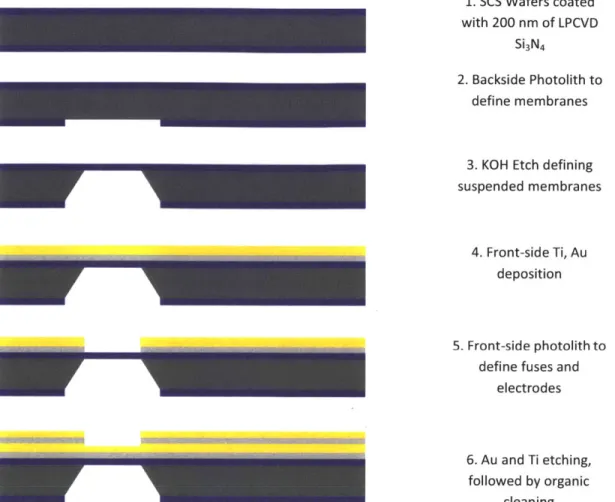
The fabrication process involves standard bulk micro-machining, shown in sequence in Figure 3.1. The first step involves the deposition of low-stress, low pressure chemical vapor deposition (LPCVD) Si3N4 on 4 inch, 300 pm thick single-crystal-silicon (SCS) wafers (orientation 100). One side of the wafer was patterned via standard photolithography and etched via reactive ion etching (RIE) to define -200 pm by 200 pm regions of bare silicon. Exposure to 20% KOH solution resulted in a self-terminating etch that created 80 by 80 pm suspended Si3N4
membranes. Titanium and gold layers were sputtered after standard organic cleaning. The Au thickness was varied at 100, 250 nm, 500 nm in order to vary the current density required to experimentally burst the membranes. The fuses were then defined using standard photolithography, followed by sequential timed wet etching steps using gold and titanium etchants. The lateral dimensions of the fuses were defined by the mask design as 80 pm long, whereas the width was varied per design as 20, 40, 60 pm.
1. SCS Wafers coated
with 200 nm of LPCVD Si3N4
2. Backside Photolith to define membranes
3. KOH Etch defining
suspended membranes
4. Front-side Ti, Au deposition
5. Front-side photolith to
define fuses and electrodes
6. Au and Ti etching,
followed by organic cleaning
Figure 3.1 Fabrication process sequence for creating nitride membranes in the microchip.
3.1.2 Three membrane devices
The same general fabrication process as outlined in 3.1.1.1 was used to generate the 3 membrane devices, except with minor edits to particular dimensions and geometries. One side of the wafer was patterned via standard photolithography and etched via reactive ion etching (RIE) to define -720 pm by 720 pm regions of bare silicon. Exposure to 20% KOH solution resulted in a self-terminating etch that created 300 by 300 pm suspended Si3N4 membranes.
Titanium and gold layers were sputtered after standard organic cleaning. The Ti thickness was set at 30 nm and the AU thickness at 250nm. The fuses were then defined using standard photolithography, followed by sequential timed wet etching steps using gold and titanium etchants. The fuse dimensions were set at 250 nm thick by 40 pm. Fuse shape was varied to
determine which geometry resulted in the greatest area of membrane rupture. Eventually, the fuse deposition step was reduced from a 2 step process to a single step deposition as lack of
conformal deposition on the second step led to variability in device activation reliability.
3.2 TMZ analytics (HPLC)
3.2.1 High Pressure Liquid Chromatography
Two methods were used to quantify TMZ using high pressure liquid chromatography (HPLC). The first method was employed for samples of TMZ in water, ACSF, and pH buffers. Briefly, 20uL of sample was quantified at 37C on Agilent 1200 SeriesHPLC using a Synchropak SCD-100, 5 um, 150x4.6 mm column (Synchrom, Lafayette, IN, USA), a flow-rate of 1 ml/min, 0.01 M Ammonium Acetate (aq):Acetonitrile (92:8) mobile phase, and UV absorption at 316 nm. A second method was used for quantification of TMZ in fetal bovine serum (FBS). The same chromatographic conditions were used with the addition of minor sample preparation. 200 uL of sample was added to 100 uL of 100ug/mL Hydrochlorothiazide. The resulting solution was vortexed and then spun at 4500 G using a MiniSpin centrifuge (Eppendorf) at room temperature for 1 minute. Samples of the supernatant were analyzed on the HPLC (These methods were adapted from Kim et al 1997) [49].
3.2.2 Stability
Stability studies were conducted in HPLC-grade water (Sigma Aldrich), phosphate buffered saline (PBS) (1x), artificial cerebrospinal fluid (aCSF) and pH7 buffer. Solutions of approximately 0.5, 0.25 and 0.1 mg/ml were made for each solvent. The resulting solutions were stored at 37 *C and sampled periodically. Samples were analyzed for TMZ content by the HPLC methods described above.
3.2.3 Solubility
Saturated solutions of TMZ were prepared in pH 1,2,3,4, and 5 buffers and in pH 7 HPLC/MS grade water. Prior to mixing with TMZ, each buffer was analyzed using the HPLC method described above to determine the presence of any interfering endogenous peaks. No interfering peaks were found. Approximately 10 mg of TMZ were added to 500 pL of each buffer solution at 37 OC. Each solution was left for 20 minutes at 37 0C with intermittent
vortexing. Solutions were then spun at 10,000 RPM for 5 minutes. Precipitate was present in all samples. Samples for HPLC analysis were prepared from the supernatant at the following dilutions; pure supernatant, 1:5, 1:10, and 1:20. All dilutions were made with the appropriate buffer pre-heated to 37 0C. Samples that read in the linear range of the standard curve were used to calculate solubility by adjusting the read concentration by the appropriate dilution factor.
3.3 Device Filling
3.3.1 Fuse Study Devices
Release study devices were assembled in the following fashion. The wafers were diced, creating chips that each contained one membrane. The chips were affixed to Pyrex@ reservoir pieces via UV cured epoxy. The Pyrex reservoir pieces are 2.2 mm thick, 6.5 mm long, 5 mm wide, and drilled to define a cylindrical reservoir with a 3.5 mm diameter. The base layer was affixed to the backside of the reservoir piece via UV cured epoxy. The devices were filled with a motorized syringe unit (World Precision Instruments, USA) to provide a precise payload volume. The input port was sealed with UV cured epoxy (Dymax, Inc) after filling the devices. The error for volume loading was estimated as 1 pL. Copper wires were soldered directly on the electric pads, and covered with UV-epoxy to prevent any contamination, and guarantee electrical isolation.
3.3.2 TMZ Devices
Reservoirs were loaded with TMZ in solid form in order to maximize payload and drug stability [37]. Polyethylene glycol (PEG) was added to displace air trapped within the packed TMZ powder, therefore reducing air bubble formation within the reservoir. Molecular weight 1450 PEG was used because its melting temperature is between 43-46 0C. The PEG,
therefore, is solid when implanted at body temperature, but the TMZ:PEG mixture can be melted at moderate temperatures [37].
The process begins by packing the reservoir with TMZ powder. The reservoir is then placed in a fixture that allows molten PEG to be pipetted onto the TMZ in each reservoir. The second half of the fixture is then joined with the first half such that a high air permeability Teflon AF membrane (Biogeneral Inc, San Diego, CA) is fixed over the PEG:TMZ surface. The assembled fixture is placed in a vacuum oven and vacuum is pulled at 55 0C for 20 minutes.
When the two halves of the fixture are joined the only path for air to travel is through the membrane and out of the fixture. The TMZ and PEG are therefore trapped within the reservoir, but air is free to flux out. Under vacuum and 55 0C conditions, the air within the powder drug
fluxes out of the reservoir through the Teflon membrane. The molten PEG is then free to wet the TMZ powder and fill in the interstices of the packed TMZ, therefore creating a homogeneous mixture of TMZ and PEG throughout the reservoir. This process is repeated (typically 3 times) until all of the air has been removed from the PEG:TMZ mixture.
3.4 Device Assembly
Polyimide coated copper leads were attached to each chip by biomedical grade cyanoacrylate (Loctite Intl.). A precision machined fixture was designed and fabricated to ensure that the gold coated copper leads aligned precisely with the copper pads of the chip and