Development and Application of Saturable
Absorbers to Femtosecond Solid-State Laser
Mode-Locking
by
Rohit Prativadi Prasankumar
B.S.E.E., University of Texas at Austin (1997) M.S. Massachusetts Institute of Technology (1999)
Submitted to the Department of Electrical Engineering and Computer Science In Partial Fulfillment of the Requirements for the Degree of
Doctor of Philosophy at the
Massachusetts Institute of Technology June 2003
@2003 Massachusetts Institute of Technology All Rights Reserved
Signature of Autho
Certified by
OF TECHNOLOGY
JUL 07 2003
LIBRARIES
Department of Electrical Engineering and Computer Science May 23, 2003
James G. Fujimoto Professor of Electrical Engineering Thesis Supervisor
Accepted by _
Development and Application of Saturable
Absorbers to Femtosecond Solid-State Laser
Mode-Locking
byRohit Prativadi Prasankumar
Submitted to the Department of Electrical Engineering and Computer Science on May 23, 2003 in Partial Fulfillment of the Requirements for the Degree of Doctor of Philosophy
ABSTRACT
Semiconductor saturable absorbers have had a major impact on the field of ultrashort pulse generation by increasing the stability and reliability of ultrashort pulse lasers, making them more useful in many applications. These versatile devices can be grown both epitaxially with molecular beam epitaxy and non-epitaxially using RF sputtering. In this thesis, the development and application of both types of saturable absorbers to self-starting mode-locking in solid-state lasers was examined.
The first part of this thesis describes the use of an epitaxially grown saturable Bragg reflector to mode-lock an extended cavity femtosecond Cr:LiSAF laser. Inexpensive single mode diodes were used as a pump source and a multi-pass cavity was used to lower the laser repetition rate. Pulses with durations of 39 fs and energies of 0.75 nJ were generated at an 8.6 MHz repetition rate. These pulse energies and durations are comparable to those produced from commercially available Ti:sapphire lasers that have a significantly higher cost.
The second part of this thesis explored the further development and application of non-epitaxially grown semiconductor-doped silica films. A novel pump-probe system with independent pump and probe wavelength tunability from 700 to 1000 nm and a time resolution of 17 fs was developed for device characterization. The linear and nonlinear optical properties of InAs-doped silica films deposited by RF sputtering were characterized as a function of fabrication parameters, including nanocrystallite size, pump and probe wavelength relative to the absorption edge, and rapid thermal annealing temperature. Guidelines for the optimization of semiconductor-doped silica films for saturable absorber applications were extracted from the experimental data. Large nanocrystallites, high annealing temperatures, and an operating wavelength close to the absorption edge were found to optimize saturable absorber performance, with a low saturation fluence of 640 pJ/cm2
obtained at 1.54 lxm. These saturable absorber devices were then designed to start mode-locking in a Cr:forsterite laser, obtaining self-starting 25 fs pulses with 91 nm bandwidth at 1.3 jim. These versatile devices can be designed for any solid-state laser system using the guidelines developed in this work and have the potential to replace epitaxially grown saturable absorbers in many applications.
Thesis Supervisor: Professor James G. Fujimoto
Acknowledgments
It is hard to believe that I am finally writing this section of my thesis, after reading so many other "acknowledgments" sections over the years I have been here at MIT and wondering what I would say when I finally wrote mine. Many people have helped me along the way and deserve thanks for their assistance and support, and at this point I'm afraid I will forget people, so please accept my apologies in advance.
I would first like to thank my thesis advisor, Professor James Fujimoto. I have learned how to do science from him and his influence will have a lasting impact on my career. I have been fortunate to work in his laboratory from the beginning of my graduate school education and can safely say that I have learned more every year I have been here. I would also like to thank Professor Franz Kaertner for his many helpful suggestions and ideas during the course of my thesis work as well as his willingness to always give them regardless of how busy he was. Thanks go to Professor Mildred Dresselhaus for serving on my thesis committee and taking the time to go over my thesis in great detail, offering many improvements along the way. I would also like to thank Professor Erich Ippen for much helpful advice over the years, and Professor Herman Haus for his help as well as for serving on both of my qualifying exam committees. Thanks also go to Cindy Kopf, Mary Aldridge, Donna Gale, and Dorothy Fleischer for keeping
all the administrative activities of the group running smoothly during the most stressful times.
I would like to thank Dr. Jim Walpole and Leo Misaggia who gave me much assistance at Lincoln Labs and were always willing to spend time working with me. It was a pleasure to collaborate with Professor Michael Ruane at Boston University and his insight and advice was always appreciated. Thanks also go to Paul Mak, whose skill and knowledge of the sputtering and annealing systems at BU averted many problems and saved me many wasted afternoons. I would also like to thank Dr. Wayne Knox for providing the SBR samples used in the Cr:LiSAF work.
I have been very lucky to work with many talented postdocs and graduate students who have helped me both in and out of the lab during my years here and have provided many fond memories of my time at MIT. Igor Bilinsky introduced me to the lab and gave me a great start in research work. I was very fortunate to learn from him during my first projects here. Boris Golubovic, Steve Boppart, Xingde Li, Wolfgang Drexler, Uwe Morgner, and Costas Pitris were also very helpful in the first few years here and I enjoyed working with them. Seong-Ho Cho gave me lots of assistance in the lab and was always available and willing to answer my questions.
I would like to thank Ingmar Hartl and Christian Chudoba for teaching me the finer details of pump-probe and autocorrelation measurements and also for lots of help with the saturable absorber work. Thanks also go to Kaoru Minoshima for helping me with organizing my trip to Japan as well as for helpful advice. It was always very helpful to talk to Thomas Schibli and discuss his many insights and ideas. It was a pleasure to collaborate with Stephane Bourquin on measuring pump-probe signals using his detector. Thanks also go to Yasu Hirakawa for his work on the Cr:LiSAF project. I would also like to thank Alphan Sennaroglu for helpful advice and insights, and I admire his desire to work on and ability to get results out of the Cr:forsterite laser system which has caused me many hours of frustration.
I would like to thank Pei-lin Hsiung, John Fini, Juliet Gopinath, Juhi Chandalia, and Aurea Zare for being great officemates and somehow managing to put up with my incessant drumming on things for many years. We had many interesting discussions that were always a nice diversion from the daily grind of lab work. Drew Kowalevicz shared many late nights in the lab with me before CLEO deadlines, and it was a pleasure to work with him and figure out things together. I would also like to thank Ravi Ghanta, Aaron Aguirre, Paul Herz, Tony Ko, and Desmond Adler for many good times and discussions in and out of the lab. I wish Vikas Sharma and Aurea Zare luck in continuing all the laser work in our group and thank them for their help with the latter stages of my projects. Thanks also go to Matt Grein for lots of good discussions about after-graduation plans and how UT-Austin is a much better school than A&M, and Dan Ripin for sharing the pain of working with Cr:based lasers. I would also like to thank the other members of the optics group, including Erik Thoen, Onur Kuzucu, Felix Grawert, Jason Sickler,
Peter Rakich, Charles Yu, Rebecca Younkin, Leaf Jiang, Kazi Abedin, and Hanfei Shen for their camaraderie.
Outside of the lab, all the friends I met and became close to during graduate school are all very much appreciated for helping me relax and take my mind off lab work, and making all the fun times and great memories we had together possible. I would also like to thank all my teachers throughout my educational career for inspiring and helping me along the way.
This section would not be complete without acknowledging my parents. They served to motivate me to explore the limits of what I could achieve when I was younger, and were always there when I needed them throughout the years. This accomplishment would not be possible without their love and support. My brother has also always supported me during all sorts of ups and downs, and been there to ground me and provide a realistic perspective on things as well as to help me relax and have fun playing video games on ancient Nintendo systems late at night. My sister's boundless energy and her million stories about all the exciting things going on in her life were always a welcome distraction from lab frustrations as well, and her courage in facing adversity has amazed me. I would also like to thank my aunt, uncle, grandmother, and cousins in New Hampshire for providing a home away from home and a place to get some real food whenever I needed it. Thanks also go to my family in India, San Francisco, and Australia for always expressing their pride for my smallest accomplishment during my years in school.
Finally, I would like to thank my fianc6, Anu, for all her love and support during the last few years of this thesis. It seems like an incredibly fortuitous series of coincidences that led to the beginning of our relationship a few summers ago, for which I would like to thank my good friend and future brother-in-law Sameer for persisting through all sorts of adversity in his attempts to win his wife's love and therefore get me introduced to his sister-in-law. I don't really know where to start in expressing how much I have learned from Anu about the things that are important in life. Her caring, thoughtfulness, courage, and strength have set a high standard for me to aspire to. My life has been enriched by her and I hope to give back to her even a small amount of the happiness she has given me during the rest of our lives together.
Table of Contents
Chapter 1
Introduction...
18
Chapter 2
Laser m ode-locking ...
23
2.1 Introduction...232.2 Passive mode-locking with slow and fast saturable absorbers... 27
2.3 Self phase modulation... 29
2.4 Dispersion...32
2.5 Gain filtering...34
2.6 The master equation for fast saturable absorber mode-locking... 34
2.7 Kerr lens mode-locking... 39
2.8 Self-starting mode-locked operation... 42
2.9 Soliton mode-locking... 44
2.10 Saturable absorbers for laser mode-locking... 46
2.10.1 M odulation depth and non-saturable loss... 47
2.10.2 Absorption saturation intensity and fluence... 48
2.10.3 Absorption saturation recovery time ... 51
2.10.5 W avelength dependence and other characteristics...53
2.11 Design of a mode-locked laser... 55
2.11.1 Four mirror cavity ... 55
2.11.3 Dispersion compensation using double-chirped mirrors... 60
2.11.4 Optimization of laser cavities for Kerr lens mode-locking ... 64
2.12 Pulse measurement... 69
Chapter 3
Previous Work on Semiconductor Saturable Absorbers and Diode-Pumped
Solid-State Lasers ...
75
3.1 Introduction...75
3.2 Epitaxially grown semiconductor saturable absorbers ... 76
3.2.1 General principles of epitaxially grown saturable absorber design ... 76
3.2.2 High finesse A-FPSA ... 77
3.2.3 AR-coated SESAM ... 80
3.2.4 Low-finesse A-FPSA (SBR)... 81
3.2.5 Broadband SESAMs ... 82
3.2.6 Semiconductor saturable absorbers for Cr:forsterite and Cr:LiSAF...83
3.2.7 Summary of previous work on epitaxially grown semiconductor saturable absorbers 84 3.3 Non-epitaxially grown semiconductor saturable absorbers... 85
3.3.1 Semiconductor-doped glass structures...85
3.3.2 Semiconductor-doped silica film saturable absorbers...87
3.4 Diode-pumped solid state lasers...92
Chapter 4
An extended cavity femtosecond Cr:LiSAF laser mode-locked with an
epitaxially grown saturable absorber ...
100
4.1 Introduction...100
4.3 Diode pump source design... 103
4.4 Operation of the Cr:LiSAF laser in a four mirror cavity ... 107
4.5 Design of a multi-pass cavity for increasing laser pulse energies ... 110
4.6 Saturable Bragg reflector design ... 120
4.7 Mode-locked operation of the extended cavity Cr:LiSAF laser with and without prisms ... 122
Chapter 5
Fabrication and characterization of semiconductor-doped silica film saturable
absorbers...127
5.1 Introduction...127
5.2 Optical properties of semiconductor quantum dots...129
5.2.1 Energy states in bulk semiconductors ... 129
5.2.2 Energy levels and linear absorption of quantum dots ... 131
5.2.3 Nonlinear optical properties of quantum dots ... 137
5.3 Experimental setup-fabrication ... 142
5.3.1 RF sputtering system...142
5.3.2 Photolithography ... 145
5.3.3. Rapid thermal annealing...146
5.4 Pump-probe spectroscopy ... 146
5.4.1 General principles ... 146
5.4.2 Novel pump-probe system with independent pump and probe wavelength tunability from 700 to 1000 nm... 150
5.4.3 Pump-probe systems operating at 1.26 and 1.5 microns... 156
5.5 Linear and nonlinear optical characterization of semiconductor-doped silica film saturable absorbers...---.---...157
5.5.2 Pump-probe measurements on films with different InAs/SiO2 ratios... 161
5.5.3 Wavelength dependence of the saturation fluence... 163
5.5.4 Fluence-dependent pump-probe measurements at 1.54 pm... 166
5.5.5 Pump-probe measurements at 1.26 m... 168
5.5.6 Effect of RTA temperature variance on absorption saturation dynamics ... 169
5.5.7 Effect of other fabrication parameters on absorption saturation dynamics... 173
5.6 X-ray diffraction measurements on semiconductor-doped silica film saturable absorbers...175
5.7 Fast dephasing times in semiconductor nanocrystallites and their effect on the saturation fluence...177
5.8 Guidelines for the design of non-epitaxially grown semiconductor-doped silica films saturable absorbers...182
Chapter 6
Self-starting mode-locking in a Cr:forsterite laser using non-epitaxially grown
semiconductor-doped silica films ...
185
6.1 Introduction...185
6.2 Cr:forsterite laser system...186
6.3 Transmissive saturable absorber device design ... 187
6.4 Laser cavity design...189
6.5 Self-starting Kerr lens mode-locking...191
Chapter 7
Conclusion ...
198
Appendix A
R F sputtering procedure...204
Appendix B
O ptics used in the C r:LiSA F laser ...
207
List of Figures and Tables
Figure 2-1. Intensity as a function of time for N=4 (gray) and N=10 (black) phase-locked modes. ... 2 5 Figure 2-2. Active mode-locking in the time domain ... 26 Figure 2-3. Pulse formation with slow saturable absorber mode-locking...28 Figure 2-4. Pulse formation with fast saturable absorber mode-locking (from ref [50])...29 Figure 2-5. (a) Electric field of a Gaussian pulse envelope with a carrier frequency defined by
equation (2.8). (b) Electric field of the pulse in (a) after propagating through a Kerr
medium and undergoing self-phase modulation ... 31 Figure 2-6. (a) Chirp, (b) pulse duration, (c) stability, and (d) bandwidth plotted as functions of
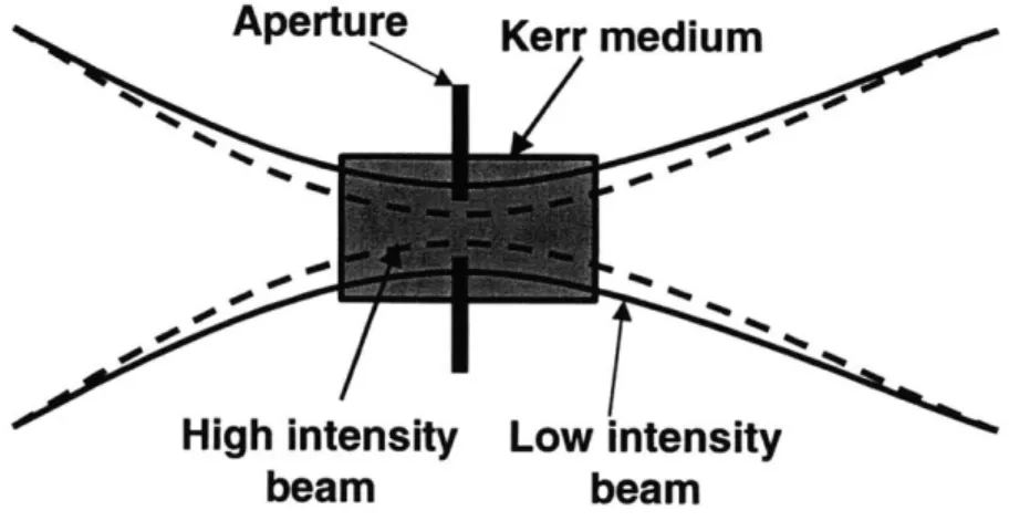
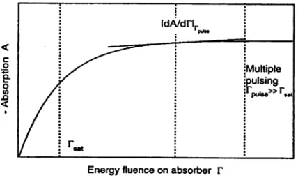
the dispersion ... 36 Figure 2-7. Schematic of Kerr-lens mode-locking with a soft aperture... 41 Figure 2-8. Nonlinear absorption change with increasing intensity... 49 Figure 2-9. Nonlinear absorption change of a saturable absorber as a function of pulse fluence.
... 50 Table 2-1. Summary of the ideal characteristics of a saturable absorber... 54
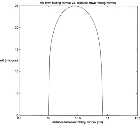
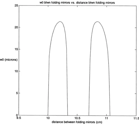
Figure 2-10. Schem atic of a z-fold cavity. ... 56 Figure 2-11. Calculated beam waist size as a function of b for a symmetric four mirror cavity.57 Figure 2-12. Calculated beam waist size as a function of b for an asymmetric four mirror cavity. ... 5 8 Figure 2-13. Dispersion compensation using a prism pair...59 Figure 2-14. (a) Standard Bragg high reflector structure. (b) Single chirped mirror structure. (c)
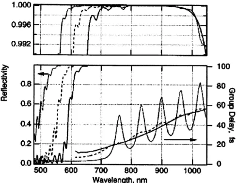
D ouble chirped m irror structure... 61 Figure 2-15. Reflectivity and group delay of chirped mirrors. The upper portion is the enlarged
top part of the reflectivity. The dotted curves display the reflectivity and group delay of a chirped mirror. The dashed curve shows the result for a double chirped mirror with a linear chirp of the thickness of the high index layers. The solid curve shows the result for a double chirped mirror with a quadratic chirp of the high index layer thickness...63 Figure 2-16. Contour lines of the Kerr-lens sensitivity (parameter of the curves) in (a) the
mirrors, and a, the distance from MI to the crystal as defined in figure 2-10, for a symmetric cavity w ith d1=d2=85 cm ... 65
Figure 2-17. Same as in figure 2-16, for an asymmetric cavity with d1=50 cm and d2=1 10 cm.67
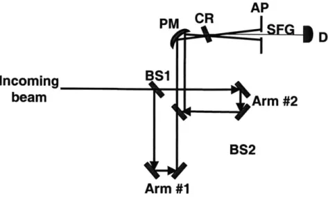
Figure 2-18. Schematic of an interferometric autocorrelator...70 Figure 2-19. Schematic of a non-collinear, background-free intensity autocorrelator. ... 72 Figure 3-1. Schematic of a typical Z cavity incorporating a saturable absorber (SA) with a
focusing mirror (CM2) with curved mirrors CM1 to focus the light into the crystal and an output coupler O C ... 77 Figure 3-2. Different SESAM designs in historical order. (a) High-finesse A-FPSA. (b)
AR-coated SESAM. (c) Low-finesse A-FPSA, or SBR ... 79 Figure 3-3. Schematic of the Ti:sapphire laser cavity used in demonstration of self-starting
mode-locking with non-epitaxially grown saturable absorbers. ... 86 Figure 3-4. Linear absorption measurement of the InAs-doped silica films...88 Figure 3-5. Compositional maps of an InAs-doped silica film taken with STEM. The image
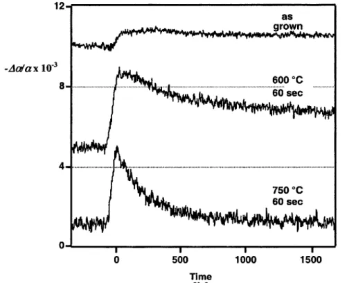
sizes are 80 by 80 nm. BF: bright field image; O:oxygen; As:arsenic; In:indium...89 Figure 3-6. Absorption saturation dynamics of InAs-doped silica films for different annealing
tem peratures. ... 90 Figure 3-7. Autocorrelation (a) and spectrum (b) of self-starting pulses from a KLM Ti:sapphire
laser incorporating an InAs-doped silica film saturable absorber...91 Figure 3-8. Schematic of the diode-pumped KLM Cr:LiSGAF laser (from [175])... 96 Figure 3-9. Schematic of the compact, single mode diode-pumped Cr:LiSAF laser (from [131]).
... . ... -.. ----... 9 8 Table 4-1. Physical and optical properties of some common solid-state laser crystals...102 Table 4-2. Diode beam sizes measured in the tangential and sagittal planes using a ThorLabs
beam profiler. ... 104 Figure 4-1. Schematic of the diode pump source... 105 Table 4-3. Measured beam radius for each diode in the tangential and sagittal planes at a
distance of 5.4 cm from M l. ... 105 Figure 4-2. Absorption and emission cross sections for Cr:LiSAF for the electric field polarized
both parallel (top plot) and perpendicular (lower plot) to the crystal axis at a temperature of 2 9 5 K ...---... 10 6
Figure 4-3. Schematic of the x cavity Cr:LiSAF laser... 107
Figure 4-4. Measured transmission of the ARO high reflecting mirrors used in the Cr:LiSAF laser cavity. (a) Full scale. (b) Close up of the reflectivity. The transmission is <0.1% from 785-935 nm . ... 108
Figure 4-5. Measured transmission of the output coupler used in the Cr:LiSAF laser cavity. The transm ission is <1.5% from 818-895 nm ... 108
Figure 4-6. Schematic of a multi-pass cavity with four bounces on each mirror. The beam is introduced and extracted through notches in the mirrors... 112
Figure 4-7. Possible unit cells for the unity q transformation in an MPC. The cavity is unfolded, representing the mirrors with lenses, and the reference planes are depicted with vertical lines. ... 112
Figure 4-8. Schematic of the MPC used in this work.. ... 114
Figure 4-9. Calculation of the mirror separation for the flat-curved mirror cavity as a function of n, for different values of m ... 116
Figure 4-10. Calculation of the repetition rate for the flat-curved mirror cavity as a function of n, for different values of m ... 116
Figure 4-11. (a) Reflectivity of the DCMs used in the Cr:LiSAF laser. The step in the data at 800 nm is due to a detector change. This figure shows the high reflectivity bandwidth of these DCMs. (b) Calculated and measured dispersion of the DCMs (obtained from V. S ch euer)... 1 18 Figure 4-12. Schematic of the extended cavity Cr:LiSAF laser... 120
Figure 4-13. Device structure (a) and reflectivity bandwidth (b) of the SBR [128]... 120
Figure 4-14. Schematic of the x cavity Cr:LiSAF laser with an SBR... 121
Figure 4-15. Experimental setup of the extended cavity femtosecond Cr:LiSAF laser... 122
Figure 4-16. Autocorrelation (a) and spectrum (b) of the extended cavity Cr:LiSAF laser using prisms for dispersion compensation. The output power in this configuration was 5.5 mW at an 8.4 MHz repetition rate, resulting in pulse energies of 0.66 nJ... 123
Figure 4-17. Autocorrelation (a) and spectrum (b) of the extended cavity Cr:LiSAF laser using only DCMs for dispersion compensation. The output power in this configuration is 6.5 mW at an 8.6 MHz repetition rate, resulting in pulse energies of 0.75 nJ... 124
Figure 4-18. Mode-locked and cw output power of the extended cavity Cr:LiSAF laser as a function of (a) DI pump power, with D2 and D3 held constant at a total power of 90 mW, (b) D2 pump power, with DI and D3 held constant at a total power of 90 mW, and (c) D3 pump power, with DI and D2 held constant at a total power of 90 mW. The mode-locked
slope efficiency is 12.8% for DI, 11.6% for D2, and 8.3% for D3. ... 125
Figure 5-1. Density of states g
(E)
for a quantum dot compared to the bulk density of states g ....133
Figure 5-2. Schematic depiction of spectral hole burning: (a) The absorption of the semiconductor before (solid line) and after (dashed line) the pump pulse. (b) The absorption change calculated from (a)... 138
Figure 5-3. Calculated effect of band-gap renormalization. The curve labeled "1" shows the absorption of the semiconductor before high intensity optical excitation; the peaks are due to exciton absorption. The curve labeled "2" depicts the absorption after pulsed excitation and clearly shows the shift of the band gap to lower energies due to band gap renormalization, along with the disappearance of the excitonic peaks ... 139
Figure 5-4. RF sputtering system .. ... 143
Figure 5-5. Schematic of the sputtering target used to deposit InAs-doped silica films...144
Figure 5-6. Schematic of the 5.4 fs Ti:sapphire laser described in ref. [90]... 151
Figure 5-7. (a) Spectrum and (b) autocorrelation of the 5.4 fs Ti:sapphire laser... 152
Figure 5-8. Schematic of the pump-probe system with independent pump and probe wavelength tunability from 700-1000 nm . ... 152
Figure 5-9. Prism compressor used to select spectral components within the 700-1000 nm bandwidth of the Ti:sapphire output spectrum ... 153
Figure 5-10. Cross-correlation of the independently wavelength tunable pump-probe system based on a ultrashort pulse Ti:sapphire laser, measured by phase-matched second harmonic generation in a 100 pm BBO crystal... 155
Figure 5-11. Linear transmission measurement before annealing of a 150 nm thick 10%InAs/90% Si0 2 film deposited on a sapphire substrate. ... 158
Figure 5-12. Comparison of semiconductor-doped silica films with different InAs/SiO2 ratios. The absorption edge shifts to longer wavelengths with increasing InAs/SiO2ratio...160
Figure 5-13. Linear transmission measurement of 150 nm thick 10% InAs/90% SiO2 films
annealed at different temperatures for 60 seconds in nitrogen... 161 Figure 5-14. Degenerate pump-probe measurements at 800 nm on InAs-doped silica films with
different InAs/SiO2 ratios. The black lines show the results of fitting the data with
exponential or double exponential functions, and the relaxation time constants are labeled for each curve... 162 Figure 5-15. Degenerate pump probe measurement of a 10% InAs/90% SiO2 film as a function
of wavelength, showing a decrease in saturation fluence with excitation closer to the
absorption edge. ... 163 Figure 5-16. Tunable degenerate pump-probe measurements at wavelengths of 1.54 tm, 1.48
pm, and 1.43 pm on a 40% InAs/60% SiO2 film... 165
Figure 5-17. Fluence-dependent pump-probe measurement at 1.54 pm on the 40% InAs/60% SiO2 film with the transmission curve shown in figure 5-12... 167
Figure 5-18. Degenerate pump-probe measurement at 1.26 pm of the 40% InAs/60% SiO2 film
with the transmission curve shown in figure 5-12. ... 168 Figure 5-19. Degenerate pump probe measurement of a 150 nm thick 10% InAs/90% SiO2 film
at 800 nm as a function of rapid thermal anneal temperature. Discrete changes in the
dynamics as a function of annealing temperature are observed... 170 Figure 5-20. Degenerate pump probe measurement of a 150 nm thick 10% InAs/90%
borosilicate glass film at 800 nm as a function of RTA temperature. The absorption
saturation dynamics change continuously as a function of RTA temperature...172 Figure 5-21. X-ray diffraction measurement of 10% InAs/90% SiO2 films annealed at different
temperatures for 60 seconds in nitrogen; the nonlinear optical properties of these films are show n in figure 5-19 ... 175 Figure 6-1. Linear transmission of the 40% InAs/60% SiO2 films used in Cr:forsterite laser
m ode-locking experim ents ... 188 Figure 6-2. Pump-probe measurement at 1.26 Rm on a thin 40% InAs/60% SiO2 film used for
m ode-locking a Cr:forsterite laser...189 Figure 6-3. (a) Reflectivity of the DCMs used in the Cr:forsterite laser. The reflectivity is
greater than 99.8% from 1.1 to 1.5 pm. (b) Group delay dispersion of the Cr:forsterite crystal, PBH71 prisms, and DCMs, plotted with the total intracavity dispersion...190
Figure 6-4. Schematic diagram of Cr:forsterite laser with additional fold ... 191 Figure 6-5. Interferometric autocorrelation (a) and spectrum (b) of self-starting KLM in
Cr:forsterite using non-epitaxially grown InAs-doped silica films. Self-starting 25 fs pulses with a bandwidth of 91 nm were generated. ... 192 Figure 6-6. Intensity autocorrelations at different dispersion operating points for saturable
absorber mode-locking without KLM. The peak intensity of the longer background pulse decreases as the negative dispersion increases... 194 Figure 6-7. Spectra at different dispersion operating points for saturable absorber mode-locking
w ithout K L M ... 194 Figure 6-8. Measured mode-locking build-up time for pure saturable absorber mode-locking
Chapter 1
Introduction
The ability to produce ultrashort pulses with durations shorter than 100 femtoseconds (fs) has led to many fascinating advances in science and technology. These include the generation of radiation at extreme wavelengths in the x-ray [1-3] and terahertz [4] regimes, frequency metrology [5, 6], biomedical imaging [7, 8], optical communications [9, 10], ultrafast carrier dynamics [11], coherent control [12], and attosecond pulse metrology [13-16]. These applications all benefit from one or more of the unique properties of femtosecond pulses including short time duration, large optical bandwidth, and high peak intensity. Ultrashort pulse technology has advanced to the point where pulses shorter than one femtosecond [13-15], bandwidths comparable to the optical carrier frequency [17], and intensities comparable to those at the core of stars [18] can be generated with laboratory scale, tabletop systems. A better feeling for the time scales involved can be obtained by noting that one femtosecond compares to one second as 5 minutes compares to the age of the universe.
Since the first proposal [19] and subsequent demonstration [20] of the laser, the many applications of laser technology have spurred research in this field. The first demonstration of mode-locking in a helium-neon laser generated nanosecond pulses [21], and subsequent efforts generated picosecond (ps) pulses from solid-state lasers including ruby and Nd:YAG [22, 23]. The narrow gain bandwidth of these materials limited pulse durations to a few tens of ps. The development and mode-locking of dye lasers [24] resulted in the generation of the first femtosecond pulses [25], and eventually pulses as short as 6 fs were generated from a mode-locked dye laser [26]. However, dye lasers are inconvenient to operate, since the dyes degrade and therefore must be continuously circulated, and the dyes are also often toxic and carcinogenic. Tunable vibronic solid-state lasers based on materials such as Ti:sapphire [27, 28], revolutionized ultrashort pulse generation. These crystals have broad gain and absorption bandwidths due to their vibrationally broadened energy states. Ultrashort pulse generation in solid-state lasers was accomplished by the discovery of Kerr lens mode-locking (KLM) in
Ti:sapphire [29], demonstrating a method that has been used to generate sub-100 fs pulses from several different solid-state laser systems, covering much of the visible and near-infrared frequency range.
Recent advances have enabled the routine generation of 10 fs pulses from the Ti:sapphire laser, which has become the workhorse of the ultrashort pulse laser industry. KLM has been employed to generate pulses as short as 5 fs directly from the Ti:sapphire laser oscillator [17]. Pulse compression techniques have been used external to the laser cavity to generate the shortest sub-5 fs optical pulses [30, 31]. In this regime, effects sensitive to the relative phase between the carrier and envelope of an optical pulse, such as high harmonic generation [32] and above threshold ionization [33, 34], can be observed and controlled [35], culminating in the recent generation of trains of attosecond pulses [13-15].
These many applications necessitate the further development of reliable, inexpensive femtosecond lasers, both for experiments for which the relatively low pulse energies (picojoules to nanojoules) directly from the laser oscillator are sufficient and also to serve as the seed oscillator for amplified systems producing pulses with high energies (microjoules-joules) and ultrashort durations. Semiconductor saturable absorbers are a recently developed technology that provides an intensity-dependent absorption for passive mode-locking of solid-state lasers [36-38]. These devices are typically grown by molecular beam epitaxy (MBE) and consist of one or more quantum wells grown in a mirror structure. Semiconductor saturable absorbers have several advantages: they make mode-locking more stable and insensitive to perturbations, simplify laser cavity alignment, and often provide self-starting operation. Semiconductor saturable absorbers have been used alone to generate sub-100 fs pulses in several laser systems, and with soliton-like pulse shaping have generated pulses as short as 13 fs in a Ti:sapphire laser [39]. They have also been used in conjunction with KLM to generate self-starting pulses as short as 5.5 fs from Ti:sapphire [40]. Sub-100 fs pulses have also been generated from other laser systems with semiconductor saturable absorbers, including Cr:LiSAF [41], Cr:LiSGAF [42], Cr:forsterite [43], and Cr:YAG [44].
In this thesis, the development and application of semiconductor saturable absorbers to femtosecond solid-state laser mode-locking was explored. The presented work can be logically divided into two major parts. The first part focuses on the application of an epitaxially grown saturable absorber to mode-locking a Cr:LiSAF laser pumped by inexpensive single spatial mode diodes. The goal of this work was to develop a femtosecond laser source with pulse energies and durations comparable to those of standard Ti:sapphire systems, which have pump sources that are nearly two orders of magnitude more expensive.
The second part of this work extended previous work on the development of non-epitaxially grown saturable absorbers based on semiconductor nanocrystallites doped into silica films that were deposited by RF sputtering on sapphire substrates. Non-epitaxial growth overcomes many of the limitations of epitaxially grown devices, including lattice matching constraints that limit the choice of materials and device design, bandwidth limitations, and the high cost and complexity of MBE systems. These devices were previously used to self-start KLM assisted 25 fs pulses from a Ti:sapphire laser [45, 46]. In this thesis, methods for reducing the high saturation fluence of these devices, which limits pulse generation, were investigated. The linear and nonlinear optical properties as well as the structural properties were characterized while varying fabrication parameters in an attempt to extract trends aiding in device optimization. The guidelines developed from these experiments were used to develop devices for mode-locking a Cr:forsterite laser.
The organization of this thesis is as follows:
Chapter 2 provides a detailed background on the principles of laser mode-locking. Passive mode-locking techniques and pulse shaping mechanisms are discussed in detail. The desired properties of saturable absorbers are also described. Finally, a description of important issues in mode-locked laser design is given.
Chapter 3 describes previous research on semiconductor saturable absorbers. Epitaxially grown saturable absorbers and their different designs and applications are reviewed, as well as non-epitaxially grown saturable absorbers based on bulk semiconductor-doped glasses and
semiconductor-doped silica films. Previous work on diode-pumped solid-state lasers of the colquirite family (Cr:LiSAF, Cr:LiSGAF, and Cr:LiCAF) is also described to provide background on the Cr:LiSAF laser developed as part of this thesis.
Chapter 4 describes the development of an extended cavity femtosecond Cr:LiSAF laser pumped by low cost single spatial mode diodes. The design of the key elements that make this novel laser possible, in particular the diode pump source, saturable Bragg reflector (SBR), and multi-pass cavity (MPC), is detailed. Ultrashort pulse generation using dispersion compensation with prisms and also in a prismless cavity using double-chirped mirrors (DCMs) is described, and the lasing threshold and slope efficiencies as a function of various combinations of the pump diodes are also measured.
Chapter 5 describes the characterization of semiconductor-doped silica film saturable absorbers. It starts with an overview of the linear and nonlinear optical properties of semiconductors, in particular semiconductor quantum dots. The fabrication techniques of RF sputtering and rapid thermal annealing are discussed. The pump-probe method used to measure nonlinear optical properties is explained and the development of a novel pump-probe system based on a broad bandwidth Ti:sapphire laser is described. Experiments characterizing the nonlinear optical properties of the semiconductor-doped silica films as functions of the pump and probe wavelengths, nanocrystallite size, rapid thermal annealing temperature, and other fabrication parameters are presented. The results of x-ray diffraction measurements performed on the films as a function of annealing temperature are also presented. An explanation for the high saturation fluence of these films, based on the fast dephasing time in semiconductor nanocrystallites, is discussed. Finally, guidelines for saturable absorber optimization based on the experimental results presented in this chapter are given.
Chapter 6 discusses the design and application of a semiconductor-doped silica film to self-starting mode-locking in a Cr:forsterite laser. The guidelines developed in chapter 5 are applied to design a semiconductor-doped silica film with a minimized saturation fluence at the lasing wavelength. Linear transmission and pump-probe measurements of the film used in laser mode-locking are described. The pulse durations and bandwidths generated from applying the
saturable absorber to self-starting KLM in Cr:forsterite are also presented. Further experiments on self-starting pure saturable absorber mode-locking as well as optimizing the pulse duration for self-starting KLM will also be discussed.
Chapter 7 summarizes the results presented in this thesis and proposes future research based on this work.
Appendix A details the RF sputtering procedure used in film fabrication. Appendix B lists the optics used in the Cr:LiSAF laser cavity.
Chapter 2
Laser mode-locking
2.1 Introduction
Mode-locking is the most widely used method of ultrashort pulse generation, enabling the generation of pulses down to two cycles in duration. The term mode-locking refers to the description of this process in the frequency domain as the phase locking of many axial modes simultaneously oscillating in the laser cavity. This can be understood by describing the correspondence between the output of a laser in the frequency and time domains [47]. In the time domain, the steady state electric field E(t) periodically repeats itself in each pass through the laser cavity, ending at the output coupler. This can be represented by
N-1
E N (t)= E(t -nTR) (2.1)
n=O
Here N is the number of passes through the cavity and TR is the cavity round trip time, given by
21/c, where L is the cavity length and c is the speed of light. For large N, this can also be
represented by [48]
E N (t)= E(t)0 0 (t-nTR). (2.2)
n=O
The Fourier transform of this function into the frequency domain results in
EN (c)=- E()l 4(o -n --) (2.3)
TR n=O TR
where E(oa) is the Fourier transform of E(t) with co the frequency. From this expression, it can be seen that the laser spectrum is a series of axial frequency modes spaced by wax=2;T/TR. Normally, the relative phases of these modes are unsynchronized and vary randomly in time, resulting in continuous wave (cw) laser operation with the energy concentrated within a few modes around the gain peak. This produces an approximately constant output power. Locking
the relative phases of the modes causes them to constructively interfere at a certain point in the cavity, resulting in an intense light pulse. As the mode amplitudes change with time, the point in the cavity at which they constructively interfere changes and the pulse propagates through the cavity. This can be seen from the following simple analysis. The laser field can be represented as the superposition of axial frequency modes with varying amplitudes and phases,
N-1
E(z,t) = I Ee i(o+n""-k-z'q" (2.4)
n=O
where (o is the phase, aw is the center frequency, and En is the amplitude of a given mode. If the axial modes are assumed to have the same amplitude (En=1 for simplicity) and phase (let A=O), then their output can be described as
N-1i iNw,.(-zlc) __
E(z,t)I= ez -e ''~'), (2.5)
for kn = '+ , and the intensity for z=O is given by
C
I E1 2
= sin2[Na.(t - z/c)/ 2]
1(t) =|E__t)_=_(2.6)
sin 2[W. (t - z / c) /2]
Figure 2-1 illustrates the temporal intensity profile for N=4 and N=10 modes locked in phase in a standard solid state laser cavity. This shows that the modes constructively interfere to produce a pulse train spaced by the round trip time TR=2 Z4a=10 ns. The inverse of the round trip time is the pulse repetition rate frep=1R=C/2L=100 MHz. It is clear that as the number of locked modes increases, the pulse duration gets shorter and the pulse peak intensity increases. The pulse duration can be approximated by r=TR/N, implying that as more modes are phase-locked, the pulse duration gets shorter. In most mode-locked laser systems the gain bandwidth of the laser limits the number of axial modes that can be locked together and therefore sets a lower bound on the pulse duration. For a typical Ti:sapphire laser, the gain bandwidth spans -350 nm, implying a minimum pulse duration of about 2.7 fs or one optical cycle. A typical ultrashort pulse has a bandwidth of about 100 nm, or -50 THz, implying that -500,000 modes are phase-locked for a 100 MHz Ti:sapphire laser.
100 80 -60
40
20
N=4(gray) and N=10 (black)
0 5 10 15 20 25 30 time (ns)
Figure 2-1. Intensity as a function of time for N=4 (gray) and N=10 (black) phase-locked modes.
These ultrashort optical pulses formed by the superposition of many axial modes are most often described in the time domain by the slowly varying envelope approximation. This represents the electric field in terms of a sinusoidal carrier wave modulated by an envelope that changes very slowly compared to the fast modulations in the carrier wave. This can be derived by simplifying equation (2.4)
E(z, t) = e ioQ'zc) Eee("-zc' 97, (2.7)
n=O
N-i
and with the envelope given by A(t - z / c) = Ene"(nw(-,' zIc)+,)
n=O then
E(z,t)= A(t - z/c)e'o('zc). (2.8)
This expression is also a solution of Maxwell's wave equation. This description of an ultrashort optical pulse has been shown to be valid down to pulse durations of one optical cycle [34]. It should be noted that the peak of the electric field can be offset from the peak of the envelope and effects due to this "carrier-envelope phase" become significant for few cycle pulses [34, 49]. This is represented by
E(z, t) = A(t - z / c)e"o(tZIC)+97, (2.9)
where 9p is the carrier-envelope phase. This phase factor does not affect the amplitude or spacing of the axial modes in the frequency domain and therefore was not explicit in equations (2.4)-(2.8). The carrier-envelope phase is due to the difference between phase and group velocities in the laser cavity and therefore changes from pulse to pulse. This manifests itself in the frequency
domain as an offset of the frequency comb from integer multiples of the repetition rate. Recent research has demonstrated control of the pulse-to-pulse change in phase, which has implications in both the time and frequency domains. A detailed discussion of this is beyond the scope of this thesis; the interested reader is referred to references [34] and [5].
Although the above discussion has mostly focused on the frequency domain representation, mode-locking is usually easier to analyze in the time domain using the carrier-envelope formalism. Mode-locking can be viewed in the time domain as a periodic modulation of the intracavity gain or loss that generates short pulses. This can be accomplished with both active and passive techniques. Active mode-locking relies on an intracavity modulator to change the cavity loss at a frequency synchronized to the cavity round trip time. This was used in the first demonstration of mode-locking [21]. In the time domain, the modulator introduces a periodic loss modulation into the cavity at frequency
f
m equal to the cavity repetition rate c/2L, creating a short modulation window during which the loss is less than the gain (figure 2-2). However, once the pulse is shorter than this window, it cannot decrease further in duration, and therefore the pulse duration is limited by the modulator speed.Intensity
I I I m
not gai
gain
0 TR ime
Figure 2-2. Active mode-locking in the time domain (from ref [50]). The pulse is shown on the top axis and is formed by the net gain window due to loss modulation.
This process can also be viewed in the frequency domain as the generation of sidebands at frequencies vo ± fm on the laser mode at frequency vo. Since the cavity modes are spaced by
f, the sidebands are phase-locked to the carrier frequency vo. On subsequent passes through the
frequencies vo ± 2f,. Repetition of this process generates a comb of modes separated by the
repetition rate of the laser. This has also been used in optical frequency metrology to bridge gaps between optical frequency standards, enabling measurement of unknown frequencies near the
comb frequencies [5].
Passive mode-locking is the most common method of generating ultrashort pulses and was used to generate the first sub-picosecond pulses from a dye laser. This technique relies on modulating the intracavity gain or loss by the pulse itself and has resulted in pulses as short as 5
fs directly from the laser oscillator [17]. In this chapter, fundamental principles of passive mode-locking will be reviewed. Slow and fast saturable absorption models will be discussed in section
2.2. The dominant pulse shaping mechanisms including self amplitude modulation, self phase modulation, dispersion, and gain filtering, will be described in sections 2.3-2.5 and incorporated into the master equation for mode-locking. Solutions to this equation and the influence of pulse shaping mechanisms on the output pulse duration, chirp, bandwidth, and stability will be discussed in section 2.6. Dispersion managed mode-locking will also briefly be described in this section. Kerr lens mode-locking, the mechanism by which the shortest pulses have been generated, will be described in detail in section 2.7. Conditions for self-starting mode-locked operation will be reviewed in section 2.8. Section 2.9 will describe the technique of soliton mode-locking. Optimum parameters for saturable absorber design will be described in detail in section 2.10. Finally, a discussion of the important issues in designing a mode-locked laser will be given in section 2.11, and techniques for pulse measurement will be discussed in section 2.12.
2.2
Passive mode-locking with slow and fast saturable absorbers
Passive mode-locking requires a mechanism that favors pulsed over cw operation. This is usually an intensity dependent loss or gain in the laser cavity provided by a saturable absorber. Saturable absorbers are intracavity elements that introduce lower loss for higher intensities. This can be used to discriminate between high intensity pulses and low intensity cw radiation. Saturable absorbers can be classified as either slow or fast depending on their response time relative to the pulse duration. A slow saturable absorber recovers its absorption on a time scale
longer than the pulse duration, and its transmission scales with the pulse fluence. A fast saturable absorber responds instantaneously to changes in the pulse intensity, and therefore its transmission scales with the pulse intensity. In general, saturable absorbers help form a net gain window that determines the pulse duration and stabilizes the pulse against perturbations.
Snet
* gain
0 TR -- tkme
Figure 2-3. Pulse formation with slow saturable absorber mode-locking (from ref [50]). The net gain window is formed by the combination of absorber and gain saturation.
Slow saturable absorbers cannot usually support short pulse formation alone, requiring gain saturation to help produce ultrashort pulses (figure 2-3) (except in the case of soliton mode-locking, to be described in section 2.9). The slow saturable absorber responds to the leading edge of the pulse, decreasing the cavity loss, which recovers on a long time scale. Gain saturation subsequently occurs and attenuates the trailing edge of the pulses. The combination of the two pulse shaping effects results in a window of net gain, forming an ultrashort pulse. This technique was used to generate pulses as short as 27 fs [51] in a laser using dyes as both gain and saturable absorber media. The theory of slow saturable mode-locking is described in ref. [52]. Most real saturable absorbers (usually semiconductors) respond on a time scale of nanoseconds or faster, necessitating a gain medium that responds on a similar time scale to generate an ultrashort pulse. Solid-state laser media that are the focus of most current research respond on a time scale of microseconds and therefore cannot be mode-locked using this technique.
Fast saturable absorber mode-locking is the preferred method for mode-locking most solid-state laser systems. In this technique, the saturable absorber responds instantaneously to changes in the pulse intensity, creating a net gain window with a width determined by the pulse duration
(figure 2-4). Gain saturation is not a factor in fast saturable absorber mode-locking. The challenge in using this method is to find absorbers that relax on a fast enough time scale.
sgch2
Figure 2-4. Pulse formation with fast saturable absorber mode-locking (from ref [50]). The net gain window is formed by the fast response of the saturable absorption.
In general, the theory of fast saturable absorber mode-locking describes a saturable absorber as an element shaping the pulse by self-amplitude modulation (SAM). Pulses usually form from noise fluctuations in the free running cw laser that are amplified by SAM since it favors the higher intensity noise fluctuations over the low intensity cw radiation. Self-amplitude modulation efficiently reduces the pulse duration down to picoseconds, after which other pulse shaping mechanisms such as self phase modulation, dispersion, and gain filtering take over to bring the pulse duration down to the femtosecond range. These pulse shaping processes are also incorporated into the theory of fast saturable absorber mode-locking and will be discussed below.
2.3 Self phase modulation
Self phase modulation (SPM) is a result of the optical Kerr effect. This occurs due to the nonlinear polarization response induced when a strong electric field is applied to an optical medium, given by
P = 'CO [X E + )E 2 +,E 3 +..,(2.10)
where the first term gives the normal linear response and the successive terms are the nonlinear polarization. In isotropic, homogenous media, the '2) term vanishes; however, the i') term is
intensity dependent index of refraction due to the nonlinear third order susceptibility ;(3) can be derived,
n = no + n21 , (2.11)
where no is the linear index of refraction, n2 is the nonlinear index of refraction, and the pulse envelope A(t) is normalized such that I =
IA2
is the peak intensity of the laser pulse. The Kerr effect is a nonresonant effect in most laser gain media and therefore can respond on extremely fast time scales (a few fs) [53]. In most optical crystals, n2 is positive and on the order of 10-16cm2/W.
The Kerr effect gives rise to two important ultrafast pulse phenomena: self-focusing and self-phase modulation (SPM). Self-focusing will be discussed in section 2.7 when describing Kerr lens mode-locking. Self-phase modulation is an important shaping mechanism for ultrashort pulses. Neglecting dispersion, pulse propagation through any medium with self-phase modulation can be described by an equation for the pulse envelope
aA(z,t) .
= -SjA1 A(z,t) (2.12)
az
where 5= kOn2 is the SPM coefficient and ko = 2;r/A. This results in an intensity-dependent nonlinear phase shift for a pulse described by equation (2.8), given by
Aqp(t)= -kon 2LI (t), (2.13)
where L is the length of the optical medium. The time derivative of the phase shift gives the instantaneous frequency shift,
Av(t) = d A )=-kOn2L ) (2.14)
dt dt
This implies that the frequency will vary across the pulse as the intensity envelope changes, an effect called "chirp". In most materials, the nonlinear index n2 is positive, implying that the leading edge of the pulse with dI/dt>O will down shift (red shift) the instantaneous frequency, and the trailing edge of the pulse (dl/dt<O) will up shift the frequency (blue shift) (figure 2-5). This can be explained by noting that the high intensity pulse peak sees a higher index of refraction than the low intensity pulse wings. The pulse peak will travel slower than the wings, causing the field oscillations to bunch up towards higher frequencies on the trailing edge of the
pulse and spread out towards lower frequencies on the leading edge. SPM only introduces a phase shift on the pulse and therefore does not affect the temporal intensity envelope. However, the pulse spectrum broadens due to the new frequencies generated on the leading and trailing edges of the pulse by SPM.
(a) (b)
Figure 2-5. (a) Electric field of a Gaussian pulse envelope with a carrier frequency defined by equation (2.8). (b) Electric field of the pulse in (a) after propagating through a Kerr medium and undergoing self-phase modulation. The chirp on the pulse has the same effect as normal dispersion, with higher frequencies delayed relative to lower frequencies
In a dispersive medium where the index of refraction varies with frequency, the additional frequency components on the leading and trailing edges of the pulse travel with different speeds. This can either increase or decrease the pulse duration depending on the sign of the dispersion. Pulse propagation in a medium with positive dispersion (low frequencies travel faster than high frequencies) causes the high frequencies on the trailing edge to lag behind the low frequencies on the leading edge, broadening the pulse in time. However, propagation in a medium with negative dispersion (high frequencies travel faster than slow frequencies) causes the blue-shifted components on the trailing edge of the pulse to catch up to the red-shifted frequencies on the leading edge, compressing the pulse in time. This interplay between SPM and dispersion, often called soliton-like pulse shaping, is the effect responsible for soliton generation and propagation. Solitons are waveforms that can travel over long distances without changing their shape, due to a balance between SPM and dispersion. Soliton-like pulse shaping can be
exploited in an ultrafast laser to obtain very short pulses. This underlines the importance of dispersion in an ultrafast laser, which will be discussed in the following section.
2.4 Dispersion
Ultrashort pulse propagation is strongly influenced by dispersion in the laser cavity. In general, an ultrashort pulse contains many spectral components that propagate at different speeds in the laser cavity due to dispersion, the variation of the refractive index with frequency. . Without proper dispersion management, this will cause the pulse envelope to change shape and spread out in time. Therefore, careful consideration of dispersive effects is extremely important in generation of the shortest pulses.
In general, propagation of light through a dispersive optical system causes a frequency dependent phase shift given by p(w). Ultrashort pulses described by the slowly varying envelope approximation (equation (2.8)) have a spectral phase given by
(9(L, w) = woLn(w)/c, (2.15)
for propagation through a dispersive medium with refractive index n(w) and length L. An expression for the group delay can be derived by expanding the spectral phase around the carrier frequency ab (usually the center of the frequency spectrum, although more complicated expressions can be used [34, 54]),
1
o(w) = po +(w -co)(dp/ do), +-( - )2 (d2p/dw2), +..., (2.16)
with the group delay (GD) given by Tg (w0) = (d(p/dw) and the group delay dispersion (GDD)
given by GDD(w0) = (d2,p IdW2) at the carrier frequency. Therefore, the pulse envelope
propagates at the group velocity vg (w0) = L / Tg (w0) and the carrier wave propagates with the
phase velocity v, (w) = c / n(w). Physically, the group delay refers to the time relative to the pulse envelope that different frequency components arrive at a given point in space. The group delay dispersion is a measure of how strongly the material spreads the pulse components; the larger the GDD, the larger the difference in arrival times between nearby frequency components
for a certain amount of optical path length through the material. For extremely short pulses (<10 fs), higher order dispersion terms become important, including the third order dispersion, given
by TOD(wo) = (d3op/ dw') and the fourth order dispersion, FOD(coo) = (d4p/ dO4) [55]. For example, the broadening of a 10 fs transform limited Gaussian pulse is the same for a GDD=100 fs2 , TOD= 1000 fs3 , and FOD=10,000 fs4.
The index of refraction is often given as a function of wavelength for many materials. Therefore, it is useful to express the GDD as a function of wavelength, given by [56]
GDD(A)= / 2 + A. (2.17)
4c2C2 d A d22
For a given transparent material, the refractive index is usually given in the form of a Sellmeier equation,
n2 _
B22 (2.18)
where Bk and Ck are coefficients that are given for the substance under consideration. The GD and GDD can easily be calculated from equations (2.17) and (2.18) for a particular material.
Equation (2.12) can be modified to describe pulse propagation including both dispersion and SPM. The modified equation is called the nonlinear Schr6dinger equation and is given by
.aA(z t) knaA(z, t) +6 1A12 A(z, t), (2.19)
az 2 at2
- a2k
where k# =
a
2 , the GDD per unit length. This equation is used to describe the propagation ofsolitons in optical fibers [57]. A stationary solution of this equation is the fundamental soliton, described by a hyperbolic secant function,
A,(z,t) = AO sech2 (tI)-hI.ls.
(2.20) This pulse shape is also common in passively mode-locked solid state lasers, and this equation can indeed be used to describe the pulses generated from a femtosecond solid state laser with appropriate modifications, described in section 2.6.
2.5
Gain filtering
Gain filtering is another important pulse shaping mechanism that must be considered in understanding passive mode-locking. The gain of a laser is frequency dependent, arising from the linewidth of the atomic transitions involved in the lasing process. In a real laser system, these transitions are not ideally sharp but are broadened by different homogeneous and inhomogeneous processes. Homogeneous broadening occurs when each atom has the same frequency response and arises from processes such as the finite upper state lifetime of the laser material or the coupling to vibrational phonon modes in the crystal lattice. Effects such as crystal imperfections cause the atomic lineshape to vary between atoms, giving rise to inhomogeneous broadening. In most solid state lasers, homogenous broadening is the dominant mechanism. The shape of the gain is a Lorentzian, which can be approximated by a parabolic gain profile near the center wavelength, given by
G(w)= g I- _), 2 (2.21)
where g is the laser gain at the center, aw is the center frequency, and L2g is the gain bandwidth. This frequency dependent gain tends to act as a bandwidth limiting filter that broadens pulses passing through the laser crystal, particularly for extremely short laser pulses. Pulse perturbations including multiple pulsing and cw breakthrough are also influenced by the finite gain bandwidth of the lasing transition [58] and will be discussed further in sections 2.6 and 2.10.2.
2.6 The master equation for fast saturable absorber mode-locking
The above pulse shaping processes can be incorporated into a master equation describing the time evolution of the pulse envelope A(t) for fast saturable absorber mode-locking in the steady state, first formulated by Haus [59, 60, 61] and given by