Development of Alternate Parts for the Aerospace Industry By
James Paul Tapley
Bachelor of Science in Marine Engineering Massachusetts Maritime Academy, 1999
Submitted to the Department of Mechanical Engineering and the MIT Sloan School of Management in Partial Fulfillment of the Requirements for the Degrees of
Master of Science in Mechanical Engineering O TrESC NSTTUE and
Master of Business Administration
JUN 0 8 2010
LIBRARIES
In Conjunction with the Leaders for Global Operations Program at theMassachusetts Institute of Technology
ARCHNES
June 2010
@2010 Massachusetts Institute of Technology. All rights reserved
Signature of Author
Certified b
Depa ent of Mechanical ErTeering MIT Sloan School of Management
May 7, 2010
Daniel W tney, Thesis pervisor Senior Lecturer Mec Ica Engineering
y
Certified by
(Woy E. Welsch, Thesis Supervisor ssor of Statistics and Management Science Accepted by
Debbie Berechman, Execuve Director of Masters Program y"rSo sn W IVlpwe m en tf Accepted by
David Hardt, Chairman, Graduate Committee Department of Mechanical Engineering
Development of Alternate Parts for the Aerospace Industry James Paul Tapley
Submitted to the Department of Mechanical Engineering and the MIT Sloan School of Management on May 7, 2010 in Partial Fulfillment
of the Requirements for the Degrees of Master of Science in Mechanical Engineering
and
Master of Business Administration
ABSTRACT
This thesis explores the topic of the development of alternate parts for the aerospace industry, drawing on industry examples to demonstrate methods and approaches and the benefits to firms engaged in these activities. I will explore reverse engineering techniques, obstacles, and the role regulations play in the development of alternate parts. I will also demonstrate that reverse engineering is no longer a back room secret activity, yet instead a innovative engineering discipline that if matured and leveraged properly can provide valuable benefits outside of alternate part development.
Thesis Advisor:
Daniel Whitney, Senior Lecturer Mechanical Engineering Thesis Advisor:
ACKNOWLEDGEMENTS
I would like to thank the MIT Leaders for Global Operations program for providing me support
and guidance in this project and for affording me the incredible educational experiences during my time as an LGO student.
Without the guidance and expertise of Paul Shook, Mike Mahonski, Tom Masters and many others who took the time to answer questions and provide guidance to me, I never would have been able to complete this project. I would especially like to recognize Bryan Atkins for going out of his way to ensure all my questions were answered and for his continued support with this project. He was very giving of his time and expertise and I will be forever grateful for all the support and guidance he has
provided.
I would also like to recognize Professors Roy Welsch and Daniel Whitney for providing me with
guidance and support to develop and complete this project. Thank you both for all your guidance and support during this project.
Lastly I would like to thank my wife Heather for her continual support and encouragement during my time at MIT and throughout the time we have been together. Through the periods away from home, late nights and busy days, Heather has always patiently been there to support me. I could not have made it through MIT without you. Thank you Heather!
Biographical Note
James Tapley graduated from Massachusetts Maritime Academy, Buzzards Bay, in June 1999 with a Bachelor of Science degree in Marine Engineering. Working in the US Merchant Marine, James sailed as First Assistant Engineer with the Marine Engineers Beneficial
Association for Maersk Lines Limited, US Ship Management and other major shipping lines.
James was accepted into the Leaders for Global Operations program, a dual degree program between the MIT Sloan School of Management and the MIT School of Engineering, and is currently working on his MBA and SM in Mechanical Engineering.
Table of Contents
1. Introduction ... 7
2. Industry Business M odel ... 9
2.1 Pratt & W hitney ... 11
2.2 Global M aterials Solutions ... 12
3. Aircraft Gas Turbine Engine ... 14
3.1 Gas Path Parts ... 15
3.2 Life Limited Parts... 15
4. Aircraft Alternate Parts Regulatory Provisions ... 18
4.1 Parts M anufacturer Approval ... 19
4.2 Supplem ental Type Certificate... 20
5. Alternate Part M arket... 22
5.1 M arket Reaction to GM S... 23
5.2 Obstacles to Alternate Part Developm ent ... 25
6. Reverse Engineering... 27
6.1 Geom etric Reverse Engineering... 29
6.1.1 Hand Tools ... 29
6.1.2 Digital Scan Technologies ... 30
6.1.3 Surface Scanners... 30
6.1.4 Coordinate M easuring M achines ... 33
6.2 Challenges to Reverse Engineering Technology ... 34
6.2.1 Im provem ent Solutions ... 34
6.3 M aterials Reverse Engineering... 37
6.4 Tolerancing... 39
6.5 Reverse engineering and Clock speed... 48
6.6 Organizational Im pacts ... 49
7. Reverse Engineering Benefits ... 50
7.1 Benchmarking... 51 7.1.1 Technology... 51 7.1.2 Operational Strategy ... 52 7.1.3 Tolerances... 53 7.1.4 M achining Capabilities... 53 7.2 Product Protection ... 54
8. Expanded Applications of Reverse Engineering ... 56
8.1 Repair Applications ... 56
Conclusion... 59
Table of Figures
Figure 1. W orld engine population ... 12
Figure 2. CFM56-3 engine cross sectional view ... 16
Figure 3. CFM56-3 GIMS Life Limited alternate parts... 17
Figure 4. PM A/STC decision tree... 22
Figure 5. Point cloud representation of a sample part . ... 31
Figure 6. Initial and proposed improved measurement process... 35
Figure 7. Tolerance exam ple part ... 41
Figure 8. Graph: Number of Parts Measured vs Sample Mean. ... 43
Figure 9. Graph: Number of Parts Measured vs Sample Standard Deviation... 44
Figure 10. Graph: Number of Parts Measured vs Sample Measured Tolerance. ... 46
Figure 11. Chart: Cpk values for example part. ... 47
1. Introduction
At time when commercial airlines are struggling to survive, alternate engine parts can provide commercial engine operators with an attractive means to reduce operating costs and remain competitive. This thesis examines commercial aerospace alternate engine parts and the methods used to develop these parts.
In Chapter 2, I will provide an understanding of the traditional aircraft engine business model and some of the issues Pratt & Whitney, a major OEM is facing. I will also discuss Pratt & Whitney's decision to launch the GMS program and enter the market with an offering of
alternate parts for a competitor's engine. In Chapter 3, I will discuss the aircraft gas turbine engine to provide a background on the different types of parts used within the engine. In Chapter 4, will explore the regulatory provisions that allow a firm to develop and sell alternate parts. In Chapter 5, I will discuss the alternate part market and how OEMs reacted to the GMS program. Additionally I will discuss other barriers to entry a firm faces in launching an alternate part program.
Chapter 6 will discuss reverse engineering techniques and the level of knowledge that is required to develop alternate parts for the aerospace gas turbine engine. Aerospace industry clock speed will also be discussed to understand its affect on the development of alternate parts. Additionally approaches to evaluate the scale of reverse engineering activities required to be able to manufacture alternate parts will be demonstrated. Finally the cultural affects of an organization undertaking an alternate part development program will be evaluated.
In Chapter 7 the benefits of developing alternate parts will be evaluated to demonstrate that there are many other benefits to a firm outside of the revenue streams created from the sale of alternate parts. Methods to protect a firm's own products will also be demonstrated.
Chapter 8 will discuss expanded applications of reverse engineering technologies. The similarities between a repaired OEM part and an aftermarket part will be demonstrated through a common industry repair. Finally I will conclude the benefits of reverse engineering.
Chapter 2. Industry Business Model
The aerospace engine market is comprised of three major engine manufacturers, General Electric (GE), Pratt & Whitney (Pratt), and Rolls Royce (Rolls). These three engine Original Equipment Manufacturers (OEM) compete in two market segments, commercial and military. In the commercial market, airplane manufacturers solicit engine designs from engine manufacturers for new airplane designs, awarding winners the right to produce engines for the specific airplane model. Typically there is more than one engine manufacturer offering per airplane and it is up to airplane purchaser to select the engine which best meets their particular performance needs.
In the defense market, defense agencies solicit engine designs for an airframe
independent of the airframe manufacturer. Defense awards are traditionally awarded as sole source contracts and provide the engine OEM with contractual order demands. Defense agencies traditionally fund the research and design efforts for an engine and retain ownership of the designs for security reasons. The primary focus of this thesis will be the commercial aircraft market, but many of the principles and methods discussed are also applicable to the military market.
Once the initial engine is purchased, the engine operator relies on the engine OEM to provide parts and services for maintenance and repair operations throughout the life of the engine. These residual revenue streams are maintained throughout the service life of the engine. Engine selection at the time of aircraft purchase is critical to the engine manufacturer; therefore it is typical to sell engines at or below cost to entice buyers to purchase engines
initially, relying on residual revenue streams created through selling parts and services to generate profits.
As an engine design matures and the installed base of engines increases, revenues from spare parts sales increases for the OEM. Once the installed engine base is large enough to justify the development costs of alternate parts, non OEM firms begin to enter the market
manufacturing and selling alternate parts.
As engine designs have become more complex and costly, the shift toward partnerships or joint ventures has become more prevalent. While partnerships limit the financial returns from new engine designs, they offer firms a means to share in the risk and costs of developing new engines. This is illustrated by the GP 7000, the engine powering the Airbus A380. Due to the aircraft's limited sales forecasts, Pratt & Whitney and General Electric partnered to form the Engine Alliance (EA). EA provided these firms a way to share in the project risk and cost of engine development while avoiding competing against each other in the limited A380 engine market. Other industry partnerships include International Aero Engines (IAE) which is a partnership comprised of Pratt & Whitney, Rolls Royce, MTU Aero, and Japanese Aero Engine Corporation; and CFM which is a partnership between GE and SNECMA.
The civilian aerospace market is a highly regulated industry. All civilian aerospace gas turbine engines operated in service in the United States must conform to the rules and regulations of the Federal Aviation Administration (FAA). The FAA is the agency tasked with oversight to ensure safe operation of the commercial aerospace industry. Similarly, outside of the United States, each jurisdiction has established its own regulatory agencies, with
regulations similar to those of the FAA. While there have been some efforts to establish a common set of regulations, each jurisdiction still varies.
Under FAA regulations, products operated in commercial service are certified as type certificate products. Parts used within a type certificate product are certified for use in the type certificate product. All parts replaced or repaired in a type certificate product must be
approved for use in the type certificate product that they are installed in.
2.1 Pratt & Whitney
Pratt & Whitney, a United Technologies company, is a well established in the aircraft engine business with a history of producing dependable aircraft engines dating back more than eighty years. A market leader in the design, manufacture and maintenance of aircraft gas turbine engines, Pratt & Whitney is known for its ability to produce complex dependable engines. Today Pratt & Whitney's installed engine base of more than 16,000 large commercial engines powers over thirty percent of the world's commercial aircraft fleet. In the military market, Pratt's installed engine base of nearly 11,000 military engines powers 27 air forces around the world (Pratt&Whitney).
Although Pratt's installed commercial engine base is large, it's comprised primarily of older legacy engines at the end of their lifecycles. With the new Geared Turbofan engine slated to enter the market in 2013, industry projections suggest that it would be several years before
revenues from parts and services of these new engines are fully realized. A new program could allow Pratt & Whitney to fill the transitory period between when legacy engines were phased
out and the Geared Turbofan parts and service revenues increased to levels previous held by legacy engines.
Figure 1 shows the historical and projected future trend data for the world's jet engine population. Looking at the installed engine base of Pratt & Whitney's largest engine
population, the JT8D, it is clear that Pratt & Whitney will have increasingly fewer engines in service to generate revenues from parts and service.
o OTHER
WORLDWIDE JET ENGINE POPULATION
o PW3001994 - 2004, FORECAST THRU 2014 o BR700 FORECAST m GE90 *SPEY * TAY600 53,000 * ALF502 * LF507 43,000 *TRENT o PW2000 33,000 0 JT3 m JT9D 23,000 oAE3007 m V2500 13,000 m CF34 m RB211 3,000 o PW4000 CD 00 0 NC qqt o CF6 CD M) 0) 0 0 0 "" *JTBD - .... .- 0 0 0 0\ 0 CFM56
Figure 1. World jet engine population. Pratt & Whitney's large installed engine base of JT8 engines (purple) is decreasing while the CFM56 installed engine base (blue) is growing. (Back Aviation Solutions, 2004)
2.2 Global Materials Solutions
In 2006 Pratt & Whitney surprised the aerospace industry with the announcement of a new business venture, Global Materials Solutions (GMS). GMS would develop and sell a portfolio of parts for the CFM56. The CFM56 is the design of CFM (GE and SNECMA) and the
12
exclusive engine powering the extremely successful Boeing 737. For the first time in history, one of the major engine OEMs was going to enter the market as an alternate parts supplier for another OEM's engine. In another industry first, GMS would include in its portfolio of parts, Life Limited Parts (LLPs) (Pratt&Whitney). LLPs make up the large rotating elements of a gas turbine engine and are some of the most expensive parts in an engine. LLPs account for 25% of engine materials by cost (Aerostrategy Management Consulting Group, 2007). Pratt & Whitney appeared to be going after the crown jewels of engine parts business.
Pratt's decision to enter the market as an alternate parts supplier had several effects. By entering the alternate part market, many believed that Pratt was now validating the use of alternate parts. This directly contradicted the position that Pratt and the other OEM's held, labeling alternate parts as inferior to OEM parts. Pratt's decision threatened to disturb the existing OEM engine market dynamics. Pratt was altering the long standing status quo in which LLPs were generally made only by OEMs and the door was now open for other OEMs to launch similar campaigns, possibly targeting Pratt's engine designs. Although this scenario is unlikely, Pratt's large mature engine base is an attractive target. This one new venture had the potential to turn many existing engine programs from profitable to unprofitable. With expected return on development costs of some new engine programs exceeding 20 years, the sale of alternate LLPs could potentially push the expected payback time to a period beyond the expected
lifecycle of an engine program. This could prove to be devastating to engine OEMs that were in the early years of a newly launched engine programs.
The reaction from CFM to the GMS program was strong. CFM realized the severity of the situation and took immediate action. In 2010 the total CFM56 product line had an enormous installed engine base of nearly 8500 engines in service with 1989 of those being -3 engines (CFM International). The target engine, the -3 was out of production and supplying steady streams of revenues. Every part GMS sold equated to the loss of a high margin sale for that part to CFM. On a full overhaul of a CFM56-3 engine, the cost for the 19 LLPs is
approximately $1.95 Million. With an assumed cost savings of 35%, GMS parts could save aircraft operators $685,000 on an overhaul consisting of all 19 LLPs. Utilizing a rate of
consumption of approximately one set of LLPs is used per engine every eleven years, CFM stood to lose $35.3 million in revenues per year assuming only 10% market penetration by GMS. This equates to a loss of just over 18 full sets of LLPs to GMS per year.
Chapter 3. Aircraft Gas Turbine Engine
FAA regulations designate two classifications of gas turbine.engine parts, condition based and time based. Condition based parts may remain in service as long as they meet OEM service specifications. Condition based parts can be continuously repaired to meet service specifications and returned to service. Time based parts are limited by flight cycles or operating hours and must be removed from service once the life limit of the part is reached, regardless of condition.
3.1 Gas Path Parts
Gas path parts such as blades, vanes, and air seals are condition based parts. Engine performance is highly dependent on the condition of parts in the gas path; therefore engine
performance parameters are continually monitored to determine gas path part condition. Failure of gas path parts is designed to be contained by the engine and have a low probability of causing damage to the aircraft. The majority of part failures in the gas path result in fractures and material loss caused by the extreme temperatures which parts operate in, especially in the hot turbine section of an engine. Catastrophic gas path part failure such as a lost turbine blade will also result in additional engine damage as the lost material carries through the engine striking other parts in the gas path. Due to the extreme operating environment and the need to maintain optimal engine performance, gas path parts are some of the most frequently replaced parts of the engine. Alternate part firms frequently target these high consumption parts for alternate part development.
3.2 Life Limited Parts
Life Limited Parts (LLPs) are time based parts and made up of the major rotating parts of the engine. Due to the cyclical loading and high stress loads carried by LLPs, there is a pre determined cycle life for each LLP that must not be exceeded. Failure of any one of these parts would likely result in a hazardous engine effect. Failure of an LLP in service is also likely to result in structural damage to the aircraft, with the potential of bringing the aircraft out of the sky. Before the cycle limit of an LLP is reached, it must be removed from service and discarded
to ensure safe engine operation. A cycle is defined as the power cycle an engine goes through in one take-off and landing of an aircraft.
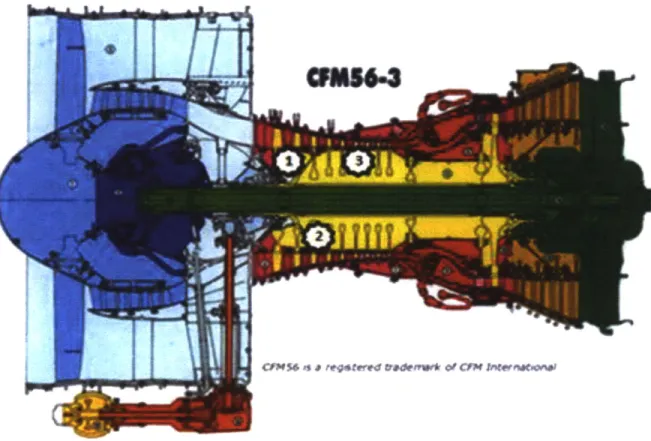
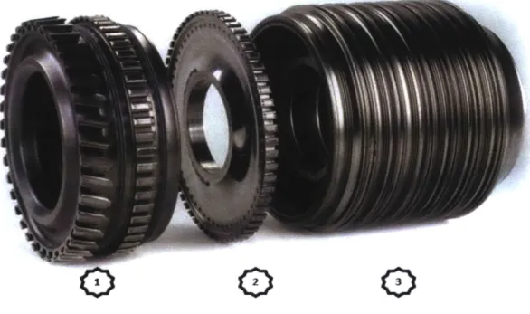
Below, Figure 2 is a cross sectional illustration of a CFM56-3 engine depicting the location of three of the nineteen LLPs in the engine. In Figure 3 is a photo of 3 GMS LLPs corresponding to the locations in Figure 2.
Figure 2. CFM56-3 engine cross sectional view. #1 denotes the HP Compressor stage 1-2 Spool, #2 denotes the HP Compressor stage 3 disk, and #3 denotes the HP Compressor Stage 4-9 Spool. (CFM)
0
0
0
Figure 3. CFM56-3 GMS Life-Limited alternate parts. #1 is a HP Compressor Stage 1-2 Spool, #2 is a HP Compressor Stage 3 disk, and #3 is a HP Compressor Stage 4-9 Spool. (Pratt & Whitney)
LLP service life is determined by the engine OEM through an FAA accepted Lifing system. A Lifing system is a complex proprietary process accepted by the FAA and used to determine
the safe operational service life of a part. The Lifing system helps designers understand
thermal, mechanical, thermo-mechanical, creep, and other stresses endured by a part during its operational life. Through a combination of tests and analytical calculations, the Lifing System used by the OEM will determine the minimum number of flight cycles required to initiate a 1/32 inch long crack on a part. A part with a 1/32 inch crack has not yet catastrophically failed, allowing maintenance inspection intervals to discover the crack so the part may be removed from service. Utilizing Lifing System data, service Life is set to a level lower than that
determined by the Lifing System to produce a 1/32 inch crack to allow for added operational safety.
While LLP failure is extremely rare, the following example demonstrates the role LLPs play in the safe operation of an aircraft and the results of an LLP failure. On July 6, 1996 Delta Airlines flight 1288 experienced an unexpected LLP failure during takeoff. The Pratt & Whitney JT8d powered McDonnell-Douglas MD-88 was on a routinely scheduled flight when during takeoff, the number 1 Front Compressor Front Hub failed leading to catastrophic uncontained engine failure. Debris from the resulting engine failure tore a hole in the left rear section of the fuselage killing two people and injuring two more. The ensuing investigation found that a fatigue crack caused by a drilling operation performed by a non OEM vendor during a repair operation had gone undetected. (NTSB, 1998)
Chapter 4. Aircraft Alternate Parts Regulatory Provisions
Traditionally engine OEMs relied on selling spare parts to generate revenue streams. Following World War II, many of the firms that had manufactured the aircraft in use had gone out of business or were not supplying parts anymore. Operators called on the FAA to develop regulatory provisions for the manufacture and use of non OEM replacement parts for use in type certificated products. The FAA developed two provisions for the manufacture and sale non OEM parts for a type certificate product, a Parts Manufacturer Approval (PMA), or a
Supplemental Type Certificate (STC). Alternate parts are commonly known as PMA or STC parts based on what method they were approved under.
4.1 Parts Manufacturer Approval
A Parts Manufacturer Approval (PMA) is a combined design and production approval for replacement parts used in commercial service. A PMA allows for the manufacture and sale of alternate parts for use in type certificate products. A PMA is granted by one of two methods test and computation or identicality. To be issued a PMA under Test and Computation, an applicant must demonstrate that the new part is identical through test and computation. To be issued a PMA under Identicality, the applicant demonstrates that the new part is identical in all aspects to the original type certificate part or by proving status as an OEM Licensee.
Identicality can be proven through identification as a licensee, or by demonstrating that the part is identical in all aspects. This is nearly impossible to do on complex designs without
providing an OEM blueprint of the product. Test and computation is the more standard approach where the applicant submits test and computational data to substantiate that the newly developed product is the same in all aspects.
Common parts receiving a PMA are nuts, bolts, gaskets, hoses, tubes, and other simple parts. In many instances OEMs were utilizing industry standard consumable items and marking them up when sold as spare parts to engine operators. Over time, aftermarket firms targeted more complex, higher margin items such as turbine blades and vanes. PMA products provide their manufacturers with generous margins, while offering engine operators discounts of 30% or more over OEM engine parts.
In an effort to increase revenues, PMA firms have sought to include LLP's to expand their portfolios of alternate parts. Without knowing part Lifing, it is impossible for a PMA applicant to demonstrate that an LLP is identical. Although the materials, dimensions and all other aspects of the part may be identical, the applicant cannot prove that their part has identical life without the use of the approved Lifing system under which the original part was certified under. Due to the fact that an OEM will never disclose its proprietary Lifing system, the part cannot be proven identical and therefore will never be granted a PMA. Utilizing an approved Lifing system other than that used to certify the original type certificate part is also not permitted. While the applicant part's Lifing may be demonstrated to be similar to the target part, it cannot be proven identical without knowing the Lifing for the original type certificate part.
4.2 Supplemental Type Certificate
Accord ing to the FAA, "A supplemental type certificate (STC) is a type certificate (TC) issued when an applicant has received FAA approval to modify an aircraft from its original design." With an STC, the design of the original type certificate design is modified. STC approval not only certifies the design changes with respect to the original type certificate design, but also approves the effects to the whole engine system as a result of those changes. STC certification of gas turbine engine parts requires a high level of knowledge of the engine on a systems level and therefore requires a higher degree of reverse engineering when compared to PMA
type certificate product did. (Federal Aviation Administration, 2008) This additional testing adds to the complexity of gaining certification for an alternate part when compared to the PMA process.
The PMA process is preferable when developing alternate parts, due to the fact that all existing OEM service documentation is still valid and applicable to the PMA part. Parts
developed under the STC process not only require an expanded scope of reverse engineering but also expanded validation data to demonstrate system effects, if any, resulting from the changes in the new parts. The STC process may also require the development of new service manuals and other service documentation due to the fact that STC parts are not identical to the original part as they are with a PMA.
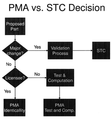
To better understand the difference between PMA and STC, the basic decision tree in figure 2 demonstrates which certification FAA certification method should be utilized when developing an alternate part.
PMA vs. STC Decision
No
Yes
-Yes N PMATest and Comnp.
Figure 4. Decision tree for determining which method of certification is required to certify alternate parts.
Chapter 5. Alternate Part Market
As commercial airlines continue to struggle financially, increased emphasis has been placed on finding ways to save on operating costs. In 2006 the aerospace industry spent $40.8 Billion on maintenance and repair of aircraft, with spending on engine materials alone
accounting for $8.6 Billion. (Aerostrategy Management Consulting Group, 2007) With engine overhauls accounting over a third of total maintenance and repair spending, alternate parts provide airline operators with a way to reduce this cost while still maintaining the same level of service and safety. Although savings of 25-45% can be realized through purchasing alternate
engine parts, the market has been slow to adopt them. In 2009 it was estimated that alternate parts penetration was only 2.9%. (Aerostrategy Management Consultants, 2009)
There are several reasons for the market not to adopt alternate engine parts. To start with, alternate parts are not offered for every OEM part. Second, the largest owner of
commercial aircraft in the world is a lease company. Lease companies have been slow to adopt aftermarket parts because alternate parts are not permitted by all regulatory jurisdictions. By allowing an aftermarket part to be used in an aircraft engine, the aircraft may not be able to be offered for lease in those jurisdictions where alternate parts are not allowed. Another reason alternate parts have not been able to gain widespread acceptance is due to well executed campaigns from the OEMs claiming that aftermarket parts are inferior and unsafe. Safety is the highest priority for an airline and most airlines are hesitant to gamble on any area relating to safety.
5.1 Market Reaction to GMS
Following the 2006 announcement of the GMS program by Pratt & Whitney, CFM immediately denounced the GMS program and the idea of alternate LLPs through a series of negative ad campaigns. The campaigns have continued through today and depict automobile coat hangers replacing broken car antennas and pictures of Elvis impersonators. In addition to negative ads, attractive long term service agreements have been offered to operators and the TRUEngine campaign was launched.
The TRUEngine campaign further promotes the long held argument used by all engine OEMs, implying that the use of aftermarket parts depreciated the value of the engine as an asset. While the TRUEngine program merely brands an engine containing all OEM materials, operators feared claims made by the campaign. According to CFM, "TRUEngine designation helps appraisers, owners, operators, and purchasers understand an engine material contentfor accurate valuation and also facilitates CFM's ability to provide optimal product support." (CFM) CFM was threatening that it was unable to provide technical support for an engine where aftermarket parts were installed, because all knowledge and expertise were based upon utilizing OEM parts. Without support from the OEM, operators would be on their own to solve complex technical issues.
Many in the industry questioned the legality of this threat due to the fact that the OEM held a legal obligation to provide product support. PMA parts are certified by the FAA as identical replacements and therefore are no different than OEM parts. On the other hand, STC LLP's while nearly identical, are not exactly the same as OEM parts. CFM was effectively adding to the scope of the GMS project by creating a situation where Pratt & Whitney had to also
provide product support for engines where GMS LLPs were installed.
Threats and negative ad campaigns from OEMs escalated to the point that in August 2008 the FAA issued a Special Airworthiness Information Bulletin defending PMA parts which have been approved by the FAA. The bulletin stated "Recently, some engine manufacturers responded to the FAA's approval of PMA and STCfor parts involving their type design engine models by telling customers that support of their products could be limited if such parts are
installed, since they do not have data on these PMA and STC parts and the effect these parts may have on the overall system." The bulletin went on to say "PMA and STC parts are
thoroughly evaluated for compliance with respect to any changes they introduce and their effect on the original type design." (Federal Aviation Administration, 2008) The FAA was making it publically clear that it did not appreciate engine OEMs openly advertising that FAA approved parts were of questionable quality and compromised safety.
Long term service agreements have been the most effective measure taken by CFM and other OEMs to combat the use of alternate parts. Long term service agreements with the OEM provide not only for the ability to control which parts are installed in the engine, but also the exclusive right to perform maintenance operations on an engine. Through controlling the engine service facility, an OEM can control what goes into the engine during repair and
overhaul. Keeping DER repaired and alternate parts from being installed into the engine, allows for the OEM to sell more OEM parts. Another benefit provided from performing engine
maintenance operations is the ability to limit alternate part development firm access to OEM parts. Alternate part development firms frequently rely on non-OEM service facilities to provide parts for reverse engineering activities. The OEM can limit the number of new OEM parts outside its control through controlling the service facilities that use these parts.
5.2 Obstacles to Alternate Part Development
Although the FAA allows for the development of alternate parts, there may be other challenges to overcome in developing alternate aerospace engine parts. The United States as well as many other nations allows inventors to control the use of their inventions through
patents, which are protected by law. To receive a patent, specific details are publically disclosed about the invention in return for exclusive rights to that invention. Patented
materials are protected by law and unauthorized use of patented inventions is subject to legal actions by the patent holder. Under current US law, patents filed after June 1995 protect claimed inventions for a period of 20 years from the date of filing. Once a patent expires, details about the invention disclosed within the patent can be freely used.
Some information may not be patented due to the disclosure provisions mandated by the patent process. Proprietary information that is kept secret and not patented is known as a Trade Secret. The advantage of a Trade Secret is that it has no expiration date and information is not disclosed. A trade secret is maintained proprietary until the information is discovered through reverse engineering or other ethical means. Trade Secret information acquired as a licensee or through a general terms agreement cannot be used for reverse engineering purposes.
In many cases the data needed to reverse engineer a product is readily available but cannot be used because it has been obtained pursuant to a license agreement. Under a license agreement information is provided about an item, to be used for specific purposes such as operation, maintenance, or repair. Information received through a general terms agreement cannot be used for reverse engineering or any other purposes unless specifically stated in the agreement under which the information was provided.
An example of a general terms agreement can be found by examining the maintenance manual for an engine. Frequently OEMs provide maintenance and overhaul services for
competitor engines. The service manuals are given to the service facility for the express purpose of overhauling engines utilizing OEM parts. Within the manual may be specific tolerance data and other blue print information that is used in the maintenance and repair of the engine. The information contained within the manual is provided under a general terms
agreement and cannot be used to establish data for reverse engineering activities or for any other purpose other than the overhaul of engines. While many firms ignore general terms agreements, ethical values should be used to ensure that proprietary information is not used for any other means than previously agreed to.
Chapter 6. Reverse Engineering
The question arises, how does one make an alternate part? An engine OEM will never hand over the blue prints on how to make a part. Although established industry practices can provide general clues about a part, specific detailed information is required to reproduce parts. Through a process called reverse engineering, sample OEM parts are used to obtain the data needed to reproduce that part. Reverse engineering is the method by which information about a product is discovered. Reverse engineering processes seek to determine part
materials, geometric dimensions, and the original design intent of a part. For parts that are incorporated in complex systems like a gas turbine engine, it may be necessary to reverse engineer the supporting parts and systems to better understand the target part.
Part characteristics greatly contribute to the performance of a part and need to be understood for several reasons. Material properties and geometric variability, not only are
important to part performance, but also provide insights into how a part was manufactured. There are two types of testing to determine part characteristics, destructive and
non-destructive. Non-destructive testing is advantageous in that the part is not adversely affected by the testing process. Destructive testing methods employ procedures that damage a part in the course of the testing process, so parts must be acquired solely for testing purposes. Due to
the fact that part properties such as natural frequency and geometry will be altered during destructive testing activities, non-destructive testing activities are conducted first.
Once the initial part is understood, it may also be desirable to understand allowable variability of different aspects of a part. To determine the allowable variability, several different samples of the OEM's part will have to be inspected to understand the extent of
variability that is allowed without affecting the performance of the part. In order to evaluate a diverse lot of parts, a firm could opt to purchase the parts, but that would prove expensive, especially if parts were only purchased solely for evaluation purposes. Many firms choose to partner with Maintenance and Repair Organizations (MROs) not operated by the OEM to minimize the cost of purchasing parts for evaluation. At the MRO facility, parts used in routine service and repair operations are evaluated whenever possible minimizing the need to
6.1 Geometric Reverse Engineering
Many non destructive inspection methods are employed to determine part geometric data. Some key factors used in determining what method to use are: accuracy level required, cost, and part complexity. For simple parts of minimal geometric complexity like a gasket, simple tools such as a ruler, micrometer or caliper may be employed to determine dimensional data. For parts of higher geometric complexity, laser scanners or other optical scanners provide a means to quickly capture geometric data of relatively high accuracy.
6.1.1 Hand Tools
Before the advent of computers and digital design techniques, hand tools such as a micrometer, Cadillac gauge, caliper, tape, pitch gauge, etc, were the only way to measure parts. Still utilized today, these types of tools are simple and relatively low cost to acquire and have a wide range of accuracy capabilities depending upon the tool used. The user of the tools reads the measurement data from the tools, sometimes leading to variability in the output data based upon the user. For more complex parts it can be difficult and time consuming to
measure parts utilizing hand tools, and therefore industry demanded faster methods capable of higher accuracy.
6.1.2 Digital Scan Technologies
Modern design practices are dependent on Cad and digital modeling techniques. Digital models allow designers to digitally design and evaluate parts to determine whether parts meet design specifications. Through utilizing digital design practices, designers can design, test and refine the design of a new part without ever actually making a physical part. More commonly known as finite element analysis, this digital analysis reduces engine design cost and time. In addition to being utilized by designers, solid models are also used in manufacturing operations to control Computed Numerical Controlled (CNC) machining operations and to automate inspection equipment such as Coordinate Measuring Machines (CMM).
Modern design practices require dimensional data in a digital format. Digital scanners utilized for reverse engineering have been developed to support this requirement. Two types of 3-D scanning technologies have evolved; non-contact and contact scanners. Contact
scanners require contact with the part, while non-contact scanners are able to gather data without contact with the part.
6.1.3 Surface Scanners
Surface scans provide their user with rapid digital dimensional data collection of an object. Laser scanners, Atrophic Optical Scanners (ATOS), structured light, and photogrammetry are some of the current surface scanning technology in use today. Output data from surface scanner devices is digital and typically in the form of what is known as a point cloud.
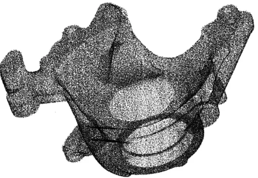
Point cloud data is exactly as its name states, a digital representation of the part made up of millions of points representing the geometry of the scanned area of the object. Figure 5
below illustrates a point cloud representation of a sample part. Point cloud data can be used to determine dimensional data for the scanned part, but the large file size can be difficult to handle and requires a computer with a high computing capability. The view area of surface scanners can also be limited. The output point cloud from a single scan is made up of a fixed number of points, so as the scan area increases the point cloud density per unit area of the part goes down. Through attaching reference targets to the part and performing multiple smaller, high resolution scans which incorporate reference targets, several scans can be joined together in the scanner software utilizing the reference targets to align the scans. This is especially useful for large objects or parts that require high accuracy but are larger than the view area that will yield the required accuracy.
Although dimensional measurement data can be extracted from the point cloud, most Cad software is not able to process point cloud data. Special software packages are employed to convert point cloud data to NURB surfaces or triangulated polygonal mesh formats.
Polygonal Mesh and NURB surface formats can be read by most CAD packages, but lack the feature distinction of a solid model.
Another limiting factor to surface scan technology is ability to gather complete data. Surface scan only capture line of sight areas and can create what are referred to as "holes" or areas which are not captured and represented in the point cloud. Holes can result from inaccessible or limited access areas of a part or noise in the data creating areas that were not able to be captured by the scanner. Inaccessible areas will require secondary scans or another suitable means of inspection. Software packages can be used to fill "holes" through manual manipulation, automatic means, or through grafting in other point cloud data over the hole. Care must be taken to ensure software has correctly interpreted and filled "holes" with secondary measurement typically employed to verify this.
Surface finish of a part can also limit the effectiveness of surface scan technologies. Shiny or metallic parts with a polished surface finish sometimes require coating with a non reflective material such a talcum powder to reduce reflectivity. While every effort is made to use anti-reflective coatings of minimal thickness, the coating will add some thickness to the part geometry. The use of anti-reflective coatings also can lead to inaccurate part measurements due to the method of coating application. While every attempt is made to apply the coating
evenly, the possibility of non-uniform coating thickness exists and can lead to inaccurate measurements.
6.1.4 Coordinate Measuring Machines
The measurement of aerospace parts requires extremely high accuracy. While hand tools and surface scanners can be employed, aerospace industry practices have looked to the higher accuracy data offered by CMM technology to gather dimensional data. When reverse engineering activities commence, CMM technology is employed to determine dimensional data so that solid models can be created to support design and certification activities. Normal
operating procedures for CMM technology require the use of automated programs based on a solid model of the part to drive the CMM machine in an automated mode. Without a solid model of the part, the CMM has to be operated in manual mode, requiring the operator to manually maneuver the probe over the part utilizing a joystick. This manual process is extremely time consuming and requires a large amount of on machine time and highly skilled operator. Once the first part is inspected, a solid model can be created so that subsequent parts can be measured through automated CMM operation. The ability to expedite first part inspection would provide for a multitude of benefits.
6.2 Challenges to Reverse Engineering Technology
A major challenge to achieving high accuracy measurement is the need for a solid model of the part to drive the CMM. The question arises, how can one create a solid model to drive the CMM if the CMM is being utilized to create the solid model? A process that can reduce on
machine inspection time and the need for a highly skilled operator is highly desirable for several reasons. The skill level required for complex parts utilizing manual CMM control severely limits the pool of eligible CMM operators. Once a qualified operator is found, this manual process is extremely time consuming and ties up the CMM operator and CMM. Only one part can be inspected at a time without purchasing another CMM and finding and hiring another qualified CMM operator.
6.2.1 Improvement Solutions
Some efforts have been made to address the issue of utilizing CMM technologies for first article inspection. For symmetrical parts, partial CMM trace scans are completed, then body of revolutions around the scan are created in modeling software to create simple solid models to automate the CMM. This method relies on part being symmetrical with many of the features still having to be manually probed by the CMM. Non symmetrical parts will still have to be measured in the traditional manner.
Utilizing rapid scan technologies to create an initial point cloud model could provide a first step toward finding a solution. While the accuracy level is not that of CMM technology and the output format is not a solid model, surface dimensional data is acquired. Software packages are capable of converting the point cloud data to formats that can be recognized by
CMM programs. Through using software to convert the point cloud to a polygonal mesh, a simple featureless solid model could be created. Utilizing feature recognition software, a CAD programmer could utilize rapid scans to designate part features in the solid model. The solid model could then be programmed to automate the CMM. While some areas may still require manual CMM operation, a majority of most parts could be measured through an automated means. Programming could be done off line at a low cost outsource, to reduce machine
measurement time and CMM operator time. CMM measurement would also not be dependent on specific CMM operator locations, expanding the availability options.
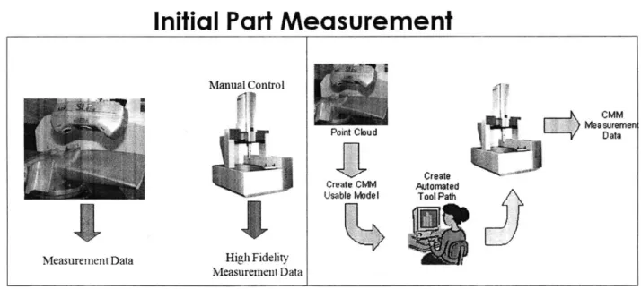
In Figure 6, the left diagram demonstrates the existing process used by many firms. Parts are measured with a laser scanner and manually on a CMM. The right diagram in Figure 6 demonstrates the proposed new process where parts are measured on the CMM by automated means.
Initial Part Measurement
Manual Control OW mrCMM Measuremeni PointCloudData
Create
Create CMM AutomatedUsable Model Tool Path
Measurement Data High Fidelity Measurement Data
Figure 6. Initial part measurement process is shown on the left, while the proposed improved process is shown in the figure on the right.
The question arises, why not just secretly acquire a blueprint or use other information that you may be able to gain access to and avoid all the costly and time consuming reverse engineering? Some parties indeed choose to acquire part blue prints and other proprietary information unethically. Technical manuals and other information about products are usually given for maintenance and repair operations under a license agreement. Such agreement only allows for the information to be used for the purposes that it was supplied for. Utilizing any proprietary information covered by a licensee agreement for reverse engineering or the development of alternate products is not only unethical, but may expose the licensee to legal action. Similarly care should always be taken to ensure that all materials used for reverse engineering activities were acquired through legal and ethical means.
There are some legal and ethical means to acquire proprietary information about a part. During the reverse engineering process, a patent search should be conducted. A patent search is used to determine whether there is any protected intellectual property related to the part. If there are patents filed relevant to the part the patents may be expired, contain claims that were too narrowly drafted, or prior art may exist that invalidates the patent. If a non
authorized user can realize the benefits of patented materials by making slight alterations to the patented invention without violating the protections of the patent as written, then a patent is considered to be too narrowly drafted. Regardless of whether or not a patent is still valid, the information contained in the patent may be useful for reverse engineering purposes. Valuable information can be gathered at little to no cost from a patent due to the fact that an applicant
must publically disclose all information pertaining to their invention in order to receive a patent. A patent specification must describe how to make and use the invention such that one skilled in the art must be enabled to make and use the invention. The disclosure of patented information is required so that society may learn and progress from the invention. As part of that progress, a firm can utilize existing patent information to provide insights into the
technologies used by competing firms in order to develop new technologies of its own. Once a patent expires, any data disclosed within that patent may be freely used for any means
including the development of alternate parts.
6.3 Materials Reverse Engineering
Materials reverse engineering seeks to determine not only the materials that a part are composed of, but also the processes which were used to manufacture a part. Several samples of the same alloy of a metal can have varying properties depending on how the alloy is
processed. Understanding how a part has been processed is critical to developing alternate parts which can meet the same performance standards as an OEM part. Due to the extremely complex nature of determining material properties, external laboratories that specialize in this field are frequently employed to determine material property characteristics.
Non-destructive tests are performed to evaluate characteristics such as natural
frequency, surface finish, surface hardness, and mass of a part. Evaluations of tool marks and other visual surface finishes give clues to establish which processes were used to manufacture the part. For example, a highly polished surface finish typically requires a higher cost to
produce than a rough finish. Why would the OEM intentionally spend more money for a higher
level of finish? The surface finish of a part is an intentional design feature that contributes to performance and must be understood and incorporated in alternate part designs.
Material composition is determined through destructive testing means. An OEM part will be cut open with samples removed at different locations in order to understand how
materials vary throughout the part. Part samples are evaluated for material properties such as grain structure, stress, strain, creep, ultimate strength, yield and material chemical
composition. The test results of each sample are compared with established industry standard specification data to determine the specific material of a part and any processes that may have been used to treat that material.
Surface coatings are also evaluated utilizing destructive testing. Coating thickness is measured during part cut up, or by removing some of the surface coating in specific locations. Samples of the coating are used to determine its material properties and chemical composition. The test results of each of these samples are also compared with established industry standard
specification data to determine the specific material composition of the coatings and the processes that may have been used to apply them.
Frequently materials, coatings, or process used in the manufacture of an OEM part are patented. When this occurs, alternate part development firms must work around those patents to develop materials, coatings, or manufacturing processes that will yield parts whose properties still maintain the same properties as the OEM part. This task can be quite
challenging, but can generate materials, coatings, or manufacturing processes that are eligible for their own patents. Generating new intellectual property of this nature can be very
beneficial. A firm can leverage the benefits of this new intellectual property to improve the designs of other products it produces.
6.4 Tolerancing
Machining and other manufacturing processes used to manufacture parts are not perfect processes and yield some variability. This type of variability is accounted for in the design of a part and commonly known as tolerance. Tolerance is the allowable variance from a designated nominal. Tolerance values are designated on a blue prints and other
documentation used to manufacture a part. To be able to design an alternate part, a firm must understand the tolerances of an OEM part and how those tolerances affect the rest of the OEM engine design. Tolerances also play a critical role in the manufacture of an alternate part because there must be enough tolerance to account for variations in a firms own
manufacturing processes. If there is too little tolerance, manufacturing yields may be diminished or even zero.
Measurement of a single part equates to a sample size of 1, which has a variation of zero. By measuring multiple OEM parts, the sample size of parts is increased so that variability between parts can start to be understood. As the sample size grows, so does the confidence level that the data is representative of the sample of parts that have been produced by the OEM. The sample data can be used to determine the distribution of OEM parts. Once the distribution of OEM parts is accurately understood, assumptions about the OEMs
manufacturing capability can be made to calculate the maximum allowable OEM tolerance. This data is validated by comparing it to industry standards.
While a large sample size is desirable to establish larger tolerances, there is a cost to acquire and measure each part. Even if the part acquisition cost can be reduced to zero, there is still a cost to measure each part. Typically alternate part development firms seek to minimize development costs and therefore seek to measure as few parts as possible while still acquiring all the data needed to reproduce an OEM part. This raises an important issue that many alternate part development firms struggle with; what is the least amount of parts needed to give a representative sampling of the OEM parts and their variability?
FAA PMA regulations stipulate that alternate part dimensions must lie within those which have been measured on a new OEM part. This means that even if a firm can use
statistics to demonstrate OEM tolerances for a part, parts of those values still have to be found and measured on an OEM part. Actually having to measure every part greatly increases the cost and complexity of developing alternate parts because more parts will have to be measured to find the true OEM tolerance. While this FAA regulation does present a major obstacle, statistics can still provide useful information to an alternate development firm. Understanding the distribution of OEM parts provides a means to calculate the probability of finding a part with a specific measurement.
An alternate part development firm already has an understanding of its own manufacturing capabilities and can use this information to set a minimum tolerance level
required to profitably manufacture alternate parts. The firm can then calculate the probability and corresponding number of parts that will need to be measured to find parts that will yield this level of tolerance. By knowing the number of parts that are required to be measured,
measurement costs can be calculated to determine whether undertaking a project on this part is economical. Using estimates of the OEM manufacturing capability, an alternate part firm can determine the true OEM tolerance. If the true OEM tolerance is below the tolerance required by the alternate firm's manufacturing processes, then the firm understands that the OEM has a higher manufacturing capability. Manufacturing capabilities will need to be improved before the firm can manufacture alternate parts for this OEM part.
So how can a firm begin to understand how many parts it needs to measure? Using a know distribution for an existing part, a firm can start with a single part and evaluate changes in the level and accuracy of information about the part distribution as more samples are added. This information can help a firm understand what level of parts will be required to reproduce an OEM part.
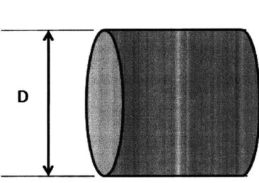
Figure 7. Tolerance example part with dimension D.
Let us now look at an example of a sample distribution of parts. Suppose we are an alternate part firm trying to determine how many parts to measure in order to understand the sample part. The part, as illustrated in figure 7, only has one feature, a diameter with dimension D.
This part is currently made by our firm and we already have data for a random population of 1000 parts. The population is normally distributed around a mean (p) of 1.0000 inches and has a standard deviation (a) of .001 inches. Removing 100 parts at random we can examine the effects on p and a for our sampling as we measure each part. We can then compare those results to the known distribution p and a to determine how accurate our results are as each part is measured. We can also evaluate what level of allowable tolerance is uncovered. By repeating this exercise several times, the effects of the exercise can be more accurately modeled.
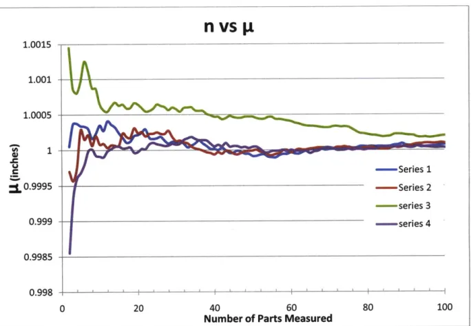
The nominal dimension of a part will be determined by p. The nominal dimension for our part is 1.000 inches. In figure 8 below is a plot of the number of parts measured versus p. This graph demonstrates how p changes as we measure each part for four different trials. We can see from the graph that p becomes apparent very quickly. By part 10 three of the four trials have come very close to the established a value for p with only series 3 being slightly off.
By part 15 there is very little change in p for each additional part measured. While p is important to establish the nominal, we are measuring more parts to understand how much variation there is around the nominal. Any shift in p can be accounted for by adjusting the nominal dimension in the blueprint. With modern Cad designs this can be set up to be done automatically.
n
vs
p
1.0015 1.001-1.0005 C -- Series 1 L0.9995 -- Series 2 --- series 3 0.999 -- series 4 0.9985 0.998 - ' 0 20 40 60 80 100Number of Parts Measured
Figure 8. Graph depicting number of parts measured versus sample mean.
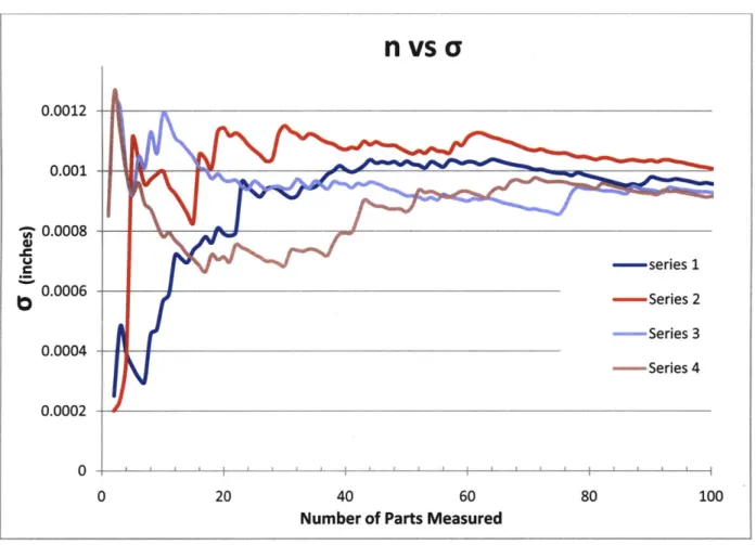
Figure 9 below depicts a plot of the number of parts measured versus aY. This graph
demonstrates how ar changes as we measure each part for our four different trials. We can see
how ay varies as we measure each part. For our known distribution we are trying to achieve a
value for ay of .001. Evaluating the graph we can see that a varies wildly until the number of
parts measured reaches 20. At 20 measured parts a is at least 75% of its final value and is
starting to settle out. By 80 measured parts ay is at least 90% of its final value with very little
fluctuation per additional part measured. We can now see that 20 measured parts starts to
improvement in accuracy and requires three times more parts to be measured. Let us now look at how this variation compares to actual tolerance measured on parts.
nvscy
0.0012 0.001 2 0.0008 .C U C 0.0006 0.0004 0.0002 0 0 20 40 60 80Number of Parts Measured
100
Figure 9. Graph depicting number of parts versus sample standard deviation.
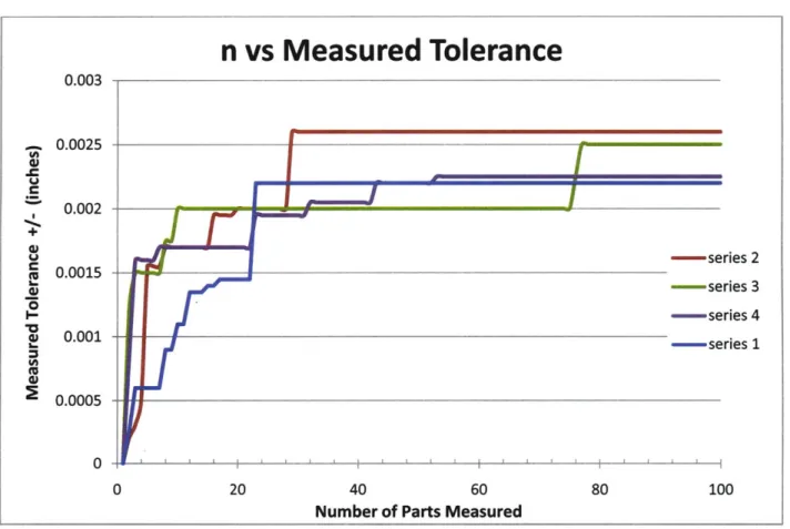
Figure 10 represents number of parts measured versus actual measured tolerance; this is one of the most important factors to an alternate part development firm in developing PMA parts. The maximum OEM design tolerance for our part is .006 inches. Examining the graph we see that after 100 measurements we never measured a set of parts that would yield a tolerance of that size. We were only able to find parts that would allow us to a tolerance of +/- .0026 inches. For the distribution we are examining there will only be 3.4 parts per million that will
be outside of the tolerances. With odds that high it will be nearly impossible to ever find and measure two of those parts. We would need two because one part would have to be on the high side of the tolerance band and the other part would have to be on the low side of the tolerance band to give us the largest tolerance possible.
Frequently alternate part firms do not need the maximum tolerance. If an alternate part firm has an equivalent manufacturing process capability to the OEM, then a smaller tolerance band can be acceptable. If the particular manufacturing process we use to
manufacture dimension D requires a +/- .002 tolerance to generate parts at an acceptable yield, then we can uses the graph in figure 10 to determine the number of parts that we will need to measure. For this situation all four trials have found parts of a +/- .002 tolerance by the time 32 parts were measured. In three trials we have measured this tolerance by part 25.
Utilizing a different situation let us assume we have a process that requires a +/- .0025 tolerance to generate parts at an acceptable yield. We can again use the graph in figure 10 again to determine how many parts need to be measured to give us the required tolerance. We can see that only two of the trials generated a tolerance of at least +/- .0025 after measuring 100 parts. Utilizing the graph, we know that it is very likely that we will need to measure more than 100 parts to find a tolerance of +/-.0025. The sample part we are using is a low volume, high cost product. In other words measuring a lot of these parts may not be an option due to the expense and availability of the part. We can still have enough measured tolerance to manufacture parts, but our manufacturing process will yield fewer parts that fall within the OEM measured tolerance. This is a common occurrence for many alternate part
development firms in any industry where tolerances are limited. What can we do? PMA parts that are manufactured outside of the measured tolerance band will be held until an OEM part is
measured that expands the tolerance level to a point where the PMA part is within measured OEM tolerances. At this point the PMA part will be within measured OEM tolerance and can be sold. By utilizing this data we can begin to understand how many parts will need to be
measured to generate measurements for the required tolerance band. Now let us take a look at how to determine what the real OEM tolerance limits are.
n vs Measured Tolerance
0.003 0.0025 0.002 0.0015 0.001 0.0005I
- series 2 -series 3 - series 4 -series 1 100 40 60Number of Parts Measured
Figure 10. Graph depicting number of measured parts versus sample measured tolerance.
In modern manufacturing there are many ways to measure manufacturing capabilities. One such way that many manufacturers use is by looking at what is known as Cpk. Cpk is a
process capability index that measures process variation to a specification like design tolerance. Most manufacturing firms operate at a Cpk of over 2.0. The formula to calculate Cpk is as
follows:
Cpk = or Cpk = p1-LCL
Where UCL is the upper control limit = upper tolerance limit, LCL is the lower control limit =
lower tolerance limit, p is the process mean and a is the process standard deviation. We can generate (p, a) for the OEM process by measuring parts and we can make assumptions about the Cpk for the OEM. Utilizing this data we can back out the UCL and LCL to give us the tolerance limits set by the OEM. Going back to our example we can calculate what the tolerance for various Cpkvalues. Below in figure 11 is a chart of those values.
Cpk 1.80 1.85 1.90 1.95 2.00 2.05 2.10 2.15 2.20 2.25 2.30 2.35 2.40 2.45 2.50 Tolerance 0.0054 0.0056 0.0057 0.0059 0.0060 0.0062 0.0064 0.0065 0.0067 0.0068 0.0070 0.0071 0.0073 0.0074 0.0076
UCL 1.006 1.006 1.006 1.006 1.006 1.006 1.006 1.007 1.007 1.007 1.007 1.007 1.007 1.008 1.008
LCL 0.995 0.995 0.994 0.994 0.994 0.994 0.994 0.994 0.993 0.993 0.993 0.993 0.993 0.993 0.993
Figure 11. chart representing ck values for example part.
We can see that for our distribution if we assume the OEM has a Cpk=2.0 then the OEM tolerance is +/- .0060 inches.
By performing simulations such as the one we have just gone through, alternate development firms can start to understand the number of parts that will be required to obtain