ELEKTROTEHNIŠKI VESTNIK 86(4):225-231,2019 ORIGINAL SCIENTIFIC P APER
Power-System Voltage Control Based THD Correction using a
Hysteresis Controller
Issam Griche
1,2, Sabir Messalti
1, Kamel Saoudi
2and Abderrazak Arabi
21Department of Electrical Engineering, Faculty of technology, University of M’sila, M’sila, Algeria
2Department of Electrical Engineering, University of Bouira, Bouira, Algeria
E-mail: [email protected], [email protected]
Abstract. The paper presents a novel voltage control method based on the THD correction using a hysteresis
controller. This structure is used as an AC/DC/AC driving system for asynchronous machine. Using the novel THD correction system enabled by a hysteresis controller turns the non-sinusoidal source current of the system into a sinusoidal waveform. Simulation and experimental results show a significant improvement of the source current due to eliminated harmonics and a notable decrease in the THD value from 28.24 to 3.25.
Keywords: voltage control, hysteresis control, THD correction, AC/DC/AC converter
Sistem za zmanjševanje višjeharmonskega popačenja z uporabo krmilnika s histerezo
V prispevku je predstavljen krmilni sistem za izločanje višjeharmonskih komponent in zmanjševanje popačenja. Sistem uporabljamo za pogon električnih asinhronskih motorjev. Z uporabo korekcijskega sistema na osnovi krmilnika s histerezo dobimo izboljšani sinusni potek električnega toka. Rezultati simulacij in meritev potrjujejo izboljšan sinusni potek in zmanjšanje faktorja popačenja z 28.24 na 3.25.
1 I
NTRODUCTIONModern electronic circuits and equipments do not behave as exactly as the linear load in an AC network. Today, one or more switching-mode converters are used in most electronic systems to draw non-sinusoidal current from the network. This current contains harmonics which distort the voltage waveform and are this lively to affed, other equipment connected to the network. Therefore, using thicker wires is being a necessity availability and efficiency. To solve this issue, an acceptable appropriate level of the total harmonic distortion (THD) needs to be assured. For this purpose, some methods and circuits have been developed and the number of these circuits and control algorithms has been increasing day by day [1-2]. In [3-4-5-6] some of the papers, dc-dc converters for THD and AC/DC/AC converter systems are used to minimize the THD values. Normally, when using a bridge rectifier for the dc-link voltage, a 70-80% of THD value of the input current is obtained [7]. In these papers, a boost converter and three-level inverter are used for the AC/DC/AC converter system. In some of the recent publications, the voltage control based THD correction is
investigated. In [8-10], a fuzzy sliding-mode controller is used for the network control system to shorten the long time-varying delays in the system. In [11-13], type II fuzzy PID single-input single-output system is applied to modify each control of the sliding mode controller. In [14-16], a sliding-mode PD fuzzy logic controller is used as a speed compensator, connect on weights values are ajusted online according to the error between the state variable of the machine and the reference model. In [17-20], a fuzzy integral sliding-mode current-control strategy is proposed to maximiz the wind-power extraction and eliminate the voltage harmonics. Recently [21], a hysteresis controller is used as a voltage controller in a single-ended primary inductor converter (SEPIC) to estimate the mismatched disturbances in the PWM-based DC-DC buck-power converter systems [22-23]. In [23-25], a voltage controller integrated in a fuzzy control is used in the boost converter. Similarly, in [26], a THD correction algorithm is presented using a hysteresis controller in affected by reference voltage and load changes in the boost converter.
Our aim is to eliminate the harmonics in the boost converter circuit connected to the output of a bridge rectifier and operated to achieve high THD values and to obtain a controlable variable of the DC voltage.
2 THD
CORRECTION USING A HYSTERESIS CONTROLLERTwo controllers are used for the voltage and current used to obtain a THD algorithm. For the converter circuits operated for THD and generat on of a variable DC voltage, a robust controller is fenerally emplyed to
Received 4 February 2019 Accepted 17 June 2019
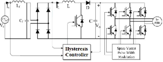
nominations in the input-output voltage, load and input current. In our study, to control the current, a hysteresis controller is used. The output voltage of dc-dc converter is employed as a DC link voltage of a two-level inverter. Because of its advantages, the Space Vector Pulse Width Modulation (SVPWM) is used to design a system for driving an asynchronous machine. Its structure setup is shown in Fig.1.
Figure 1. Structure AC/DC/AC converter.
The hysteresis control also is a nonlinear control that using the error between reference current
i
*f and the current produced by inverteri
*f [3]. The error is compared to a template called a hysteresis band. As soon as the error reaches the lower or higher band, a control command is sent so as to remain within the band. The simplicity of implementation, the principle is shown in Fig. 2.Figure 2. Principle of the current using a hysteresis controller.
The hysteresis control is an effective method to control by making the non-linear systems [3]. the principle of control is to force the output voltage or current to follow a reference sinusoidal in a band fixed by the hysteresis element. The limits of the switching band can be fixed type. For state variables of a nonlinear system are given below:
i
t
I
i
max=
msin(
)
+
(1)i
t
I
i
min=
msin(
)
−
(2) The sinusoidal limits are given by:)
sin(
)
(
maxI
i
t
i
=
m+
(3))
sin(
)
(
minI
i
t
i
=
m−
(4) The output current to be controlled is applied to the hysteresis controller and compare to the reference signal to generate the switching signal as follows:If
i
S
i
max The upper-arm switch is closed and the lower switch is open.If
i
S
i
min The upper-arm switch is open and the lower switch is closed.If
i
min
i
S
i
max No change.
Figure 3. Hysteresis control.
3 S
PACE VECTORPWM
TECHNIQUEFor a two-level voltage-source inverter, the three-phase voltages used for the SVPWM technique are represented by a voltage space vector in the α-β space using the Clarke transformation. The phase angle and amplitude of this vector can be obtained by the instantaneous values of three-phase voltages (V ,a Vb
and Vc ) are converted to the V , V components to obtain
V
ref by using Eq 5.2 2
V
V
V
ref=
+
(5)
=
−
V
V
1tan
(6) The θ angle varies and the spaces change every 60 degrees. The
angle given in Eq.6 has to be found in order to determine (sector) the place of reference voltage vectorV
ref in hexagonal voltage-vector space at next step. It is obtained using instantaneous values of the three-phase voltages [27]. The inverter is based on absence on-state of two switches on a phase-leg at the same time. Therefore, there are eight probable switching states are available depending on (on-off) states of the six switches [7]. The output voltage of inverter is determined by these eight switching states and each of these eight different switching states can be expressed with the voltage vector by given below:(
0 2 /3 2 /3)
3
2
j c j b j ae
V
e
V
e
V
V
=
+
+
− (7)where the reference-voltage values of the a, b, c phases are represented with Va, Vb and Vc and are defined by Eq.8:
POWER-SYSTEM VOLTAGE CONTROL BASED THD CORRECTION USING A HYSTERESIS CONTROLLER 227
)
3
/
2
sin(
)
3
/
2
sin(
)
sin(
+
=
−
=
=
t
V
V
t
V
V
t
V
V
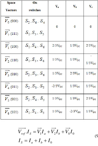
m c m b m a (8)The eight different switching states and the corresponding voltage vectors are given in Tab 1.
V
0 and V are the 7zero vectors and then others are active vectors. Accordingly, the zero and active vectors are constant but the reference vector rotates at the
angular speed. To experimental by use the SVPWM technique, need to be traced the four steps. At first step, to obtain the Vref , then, to trace the hexagonal voltage vector space in second step. At the third step, the Ta,Tb,T0 are calculated. They are the switching times of V1,V2,V0 harmonic 2 obtained in Eq.9.Table 1. The switching states of the three-phase two-level inverter 0 0 0 2 1
.
I
I
I
I
I
V
I
V
I
V
I
V
b a S b a S ref+
+
=
+
+
=
(9)For the first space, the
T
a,
T
b,
T
0 are given in Eq.10.b a S S da ref b S da ref a
T
T
T
T
T
V
V
T
T
V
V
T
+
+
=
=
−
=
0)
sin(
3
)
3
sin(
3
(10)The Ta,Tb,T0 values for the other spaces are obtained using the same method. At the last step, the harmonic order 2 of space-vector application is determined for the reference vector (Vref ) when the switching signals are generated. The harmonic order 3 of this application can be designed in several ways. To obtain minimum switching frequency and the optimum harmonic performance two requirements must be met [28].
The switching states in the voltage vector space are determined by taking into account the two requirements and space switching states.
4 S
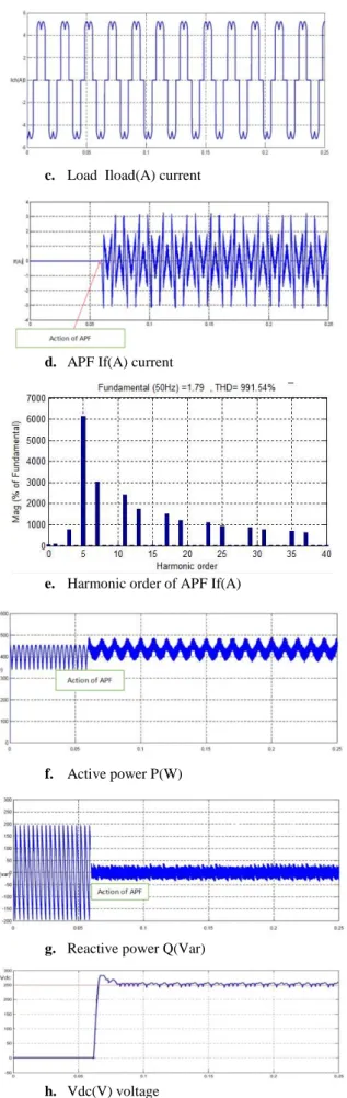
IMULATION RESULTSSimulation results using presented method are given in Fig. 4 (a,b,c,d,e,f and g)
a. Is(A) current source
c. Load Iload(A) current
d. APF If(A) current
e. Harmonic order of APF If(A)
f. Active power P(W)
g. Reactive power Q(Var)
h. Vdc(V) voltage
Figure 4. Simulation results
Fig.4 shows that at t = 0.06 the actionated the power filter starts to injecting the compensation currents (if),
which makes the currents to become almost sinusoidal and decreases from 28.24% to 3.25%, and to be phase with their corresponding voltages.
Moreover, the DC bus voltage (Vdc) storage terminales capacitor (Cdc) reaches its reference value (Vdc_ref) set at 250 V five periods.
The graphs of active P (w) and reactive power Q (Var) show that this takes place at t = 0.06s corresponding by the APF action compensates the reactive power consumed by the non-linear load current source. The results of simulating the THD minimisation from 28.24% to 3.25% are satisfactory and prove a proper functioning, efficiency and robustness of the shunt active filter against any harmonic whene using hysteresis controller.
5 E
XPERIMENTAL SETUPUsing the developed simulation programs simplifies the modeling of the designed systems. Similarly, they used hardaware materials simplify the design becase of their modular and compact structure. The structure of our AC/DC/AC converter with its THD controlled by a hyteresis controller illustrated in Fig.5 is designed and implimented for experimentaly purposes.
The DS1104 Controller Board (a control education kit and expansion box, ACE1104PX4) manufactured the dSPACE and used in our experimental setup controls the currents and voltages to enable the THD correction and generates the PWM signals for the converter and inverter circuits. This board is compatible with MATLAB/Simulink and has a primary (PowerPCPPC750GX/1GHz) and secondary processor (Texas Instruments TMS320F240/20MHz). To control the experimental setup, the control algorithm prepared in MATLAB/Simulink [31] is converted to real-time codes by using the MATLAB/Real-Time Workshop and dSPACE Real Time Interface and then by loading codes to the program memory of the DS1104 controller board. The PWM signals obtained with the designed control algorithm and Simulink are moved sent to the driving circuits by Bit I/Os of the DS1104 controller board. The system model is created by using the MATLAB/Simulink.
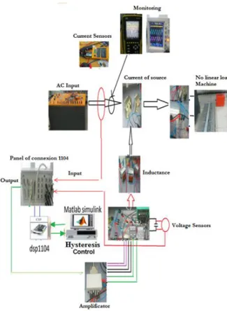
Our experimental setup consists of a variable AC voltage, AC/DC converter, resistive loads and an inductive load (induction machine), DC/AC converter by SEMIKRON, controller board amplifier and buffer circuits of the drive circuit, measurement instruments and Fluke 43B instrument used to analyse the armonics , experimental setup for the dSPACE DS1104, PC of the system model created by using MATLAB/Simulink, loads and current sensors, voltage and other components shown in Fig.5.
POWER-SYSTEM VOLTAGE CONTROL BASED THD CORRECTION USING A HYSTERESIS CONTROLLER 229
Figure 5. Structure of the designed AC/DC/AC converter.
Our simulations using the designed experimental setup are made with MATLAB/Simulink which controls the circuits and the prepared simulation blocks then used on the DS1104 platform. The simulations are there compiled to be used on the dSPACE platform. The parameters can be changed by the interfaces prepared on the dSPACE control hard. These interfaces enable seeing the online monitoring.
Figure 6. Experimental setup and other components.
The experimental setup operates at 300V of the output voltage of the dc-link voltage of the two level 300V inverter (V0=300V), 200V line voltage with a non linear
load and 50 Hz frequency of phase-voltage. 300V converter output voltage with a non linear load is obtained with the hysteresis controller and the non linear load line voltage is 220V at 50Hz.
Fig.8 shows the values of the line voltage, current and THD decrease are 220V, 3.34A and 4.3% respectevely. They are at the same time obtained also from a power analyzer. The space-vector control algorithm shows a good performance for the driving systems. As seen from Fig.8, the THD value of the phase-current is low.
Figure 7. Experimental results without controller.
Figure 8. Experimental results when using the THD controller.
( (
( (
( (
( (
6 C
ONCLUSIONAn experimentally designe AC/DC/AC converter voltage-source is controlled by a hysteresis controller enabling the THD correction. A two-level voltage- source inverter is controlled with a space-vector control algorithm. The experimental results show that the hysteresis controller is an efficien tool for THD minimization using it reduces THD input current from 25.4% down to just 3.25%. An inverter with a THD contoller can be used instead of an uncontrolled for a non linear load system because of its efficient current control, low harmonic distortion and variable dc-link. A drawback of the presented design is the need of a fast DSP. The presented design is believied to be very useful for the ful use AC/DC/AC systems. The aim of our further study is to have a unigui structure enabled by using the equipment control technigues of their rapidly developeing new technologies.
R
EFERENCES[1] Dixon, L.H.: “High Power Factor Pre-regulators for Off-Line Power Supplies”. Unitrode Power Supply Design Seminer Manual, SEM-700, 1990.
[2] Redl, R.:”Low Cost Line Harmonics Reduction”. IEEE Applied Power Electronics Conference (APEC) Professional Seminer.1995.
[3] Lee, D.C., and Kim, Y-S.:”Control of Single-Phase-to-Three-Phase AC/DC/AC PWM Converters for Induction Motor Drives”, IEEE Transactions on Industrial Electronics, 54(2), pp.797-804, 2007.
[4] Mazumder, S, “DSP based implementation of a PWM AC/DC/AC converter using space vector modulation with primary emphasis on the analysis of the practical problems involved”. Applied Power Electronics Conference and Exposition (APEC), 1, pp.306-312, 1997.
[5] Morimoto, M., Sumito, K., Sato, S., Oshitani, K., Ishida, M., Okuma, S.:”High Efficiency, Unity Power Factor VVVF Drive System of an Induction Motor”, IEEE Transactions on Power Electronics, 6(3), pp.498-503, 1991.
[6] Lin, B.: “High Power Factor AC/DC/AC Converter with Random PWM”, Aerospace and Electronic System, 35, pp.935-944, 1999. [7] Kayisli, K.: “Design and Implementation of Robust Converter
Circuits with Unity Power Factor”. PhD thesis, Firat University, 2011.
[8] Khanesar, M.A., Kaynak, O, Shen, Y., Huijun, G.: “Adaptive Indirect Fuzzy Sliding Mode Controller for Networked Control Systems Subject to Time-Varying Network-Induced Time Delay”, IEEE Transactions on Fuzzy Systems, 23(1), pp.205-214, 2014.
[9] Nasimullah, Khattak, M.I., Shafi, M.: “Chatter Free Sliding Mode Control Using Fractional Operator and Fuzzy Logic System”, Ned University Journal of Research, 12(2), pp.13-21, 2015. [10] Rahbar, S., Piltan, F., Pouladi, E., Davarpanah, H., Jowkar, S.,
“The Fuzzy (PI+D)2 Sliding Mode Scheme to Motor Vibration Control”, International Journal of u-and e-Service, Science and Technology, 8(1), pp.371-388, 2015.
[11] Ngo, Q. H., Nguyen, N. P., Nguyen, C. N., Tran, T. H., Hong, K. S., “Fuzzy sliding mode control of container cranes”, International Journal of Control, Automation and Systems, 13(2), pp.419- 425, 2015.
[12] Jiao, X., Ju J., “Design of Interval Type-2 Fuzzy Sliding Mode Controller for Hypersonic Aircraft”, Journal of Automation and Control Engineering, 4(2), pp.123-126, 2016.
[13] Shafiei, S. E., Sepasi, S., “Incorporating sliding mode and fuzzy controller with bounded torques for set-point tracking of robot manipulators”, Elektronika ir elektrotechnika, 104(8), pp.3-8, 2015.
[14] Dybkowski, M., Szabat, K.: “Direct torque control of induction motor drive system with adaptive sliding-mode neuro-fuzzy compensator”. In Industrial Technology (ICIT), IEEE International Conference, pp.714-719, 2015.
[15] Saghafinia, A., Ping, H. W., Uddin, M. N., & Gaeid, K. S., “Adaptive Fuzzy Sliding-Mode Control Into Chattering-Free IM Drive”, Industry Applications, IEEE Transactions on, 51(1), pp.692-701, 2015.
[16] Masumpoor, S., Khanesar, M.A., “Adaptive Sliding-Mode Type-2 Neuro-Fuzzy Control of An Induction Motor”, Expert Systems with Applications, 42(19), pp.6635-6647, 2015.
[17] Yin, X. X., Lin, Y. G., Li, W., Gu, Y. J., Liu, H. W., Lei, P. F., “A Novel Fuzzy Integral Sliding Mode Current Control Strategy For Maximizing Wind Power Extraction And Eliminating Voltage Harmonics”, Energy, 2015, 85, pp.677-686, 2015. [18] Yin, X.X., Lin, Y.G., Li, W., Gu, Y.J., Lei, P.F., Liu, H.W.,
“Sliding Mode Voltage Control Strategy for Capturing Maximum Wind Energy Based on Fuzzy Logic Control”, International Journal of Electrical Power & Energy Systems, 70, 45-51, 2015. [19] Arslan, Y.Z., Sezgin, A., Yagiz, N., “Improving The Ride
Comfort of Vehicle Passenger using Fuzzy Sliding Mode Controller”, Journal of Vibration and Control, 1(9), 1667-1679, 2015.
[20] Elsayed, B.A., Hassan, M.A., Mekhilef, S., “Fuzzy Swinging-Up with Sliding Mode Control For Third Order Cart-Inverted Pendulum System”, International Journal Of Control, Automation And Systems, 3(1), pp.238-248, 2015.
[21] Subramanian, V., Manimaran, S., “Implementation of a Sliding Mode Controller for Single Ended Primary Inductor Converter”, Journal of Power Electronics, 15(1), pp.39-53, 2015.
[22] Wang, J., Li, S., Yang, J., Wu, B., Li, Q., “Extended state observer-based sliding mode control for PWM-based DC–DC buck power converter systems with mismatched disturbances”, IET Control Theory & Applications, 9(4), pp.579-586, 2015. [23] Noh, B.U., Choi, H.H., “Fuzzy Integral Sliding Mode Controller
Design for Boost Converters”, Nonlinear Dynamics, 78(3), pp.1863-1875, 2014.
[24] Sahbani, A., Saad, K.B., Benrejeb, M., “Fuzzy Sliding Mode Control for Parallel DC-DC Boost Converter”, International Review of Electrical Engineering (IREE), 9(2), pp.249-254, 2014. [25] Bouafassa, A., Rahmani, L., Mekhilef, S., “Design and Real Time Implementation of Single Phase Boost Power Factor Correction Converter”. ISA Transactions, 55, pp.267-274, 2015.
[26] Kessal, A., Rahmani, L., “Analysis and Design of Sliding Mode Controller Gains for Boost Power Factor Corrector”, ISA Transactions, 52(5), pp.638-643, 2013.
[27] Deniz, E.: “Design and Implementation of D-STATCOM based on Three Level H-bridge Inverter Using Space Vector Pulse Width Modulation”.PhD thesis, Firat University, 2010.
[28] Wu, B.: “High-Power Converters and AC Drives” (IEEE Press), Hoboken, New Jersey, 2006.
GRICHE Issam received his Engineering degrees from the
Setif University of Engineering and Technology, Setif, Algeria, both in power networks in 2005 and 2008. Presently, he is pursuing the Ph.D. degree. His research interests are in power systems, power networks, FACTS, renewable energy systems, wind-generator stabilization, smart grids and transient stability.
MESSALTI Sabir was born in setif (Algeria), he obtained his
Master and PhD in Electrical Engineerig from Setif University. He has worked as an engineer in power system department. Today he is full Professor of Power Systems at Electrical Engineering department of M’sila University (Algeria). His research interests includes wind turbines, power
POWER-SYSTEM VOLTAGE CONTROL BASED THD CORRECTION USING A HYSTERESIS CONTROLLER 231
systems planning, control of electrical machines, PV systems, FACTS, HVDC, control of voltage and frequency, etc. He is author of about 40 papers published on international journals or presented in various national and international conferences. ([email protected])
SAOUDI Kamel received his bachelor, M.Sc. and Ph.D. degrees all in electrical engineering from the University of Sétif 1, in 2005, 2008 and 2014 respectively. He is currently an assistant professor at the Bouira University, Algeria. His research interests include robust nonlinear adaptive control, intelligent control, fuzzy control, power systems and renewable energy.
ARABI Abderrazakreceived his Engineering degrees from the Setif University of Engineering and Technology, Setif, Algeria. Currently, he is working toward the Ph.D. degree from Setif 1 University, Setif, Algeria. As an assistant professor, he is now also working in the Bouira University, Algeria. His research interests include analog and digital circuit test, fault coverage, detection and classification.