Component-Based Specification of
Software Product Line Architecture
Amina Guendouz
CS Department, Saad Dahlab University Blida, Algeria
Djamal Bennouar
CS Department, Akli Mohand OulHadj University Bouira Algeria
Abstract – Software product lines have known an increasing use over the last years, taking advantage from the important benefits they may bring to software development in terms of time, cost and effort. However, product line approaches remain immature owing to the fact that they still base on traditional design concepts of software engineering which are not adequate to the basic principles of software product lines engineering. Considering that software product lines are inspired by industry where production activity is based on assembling certified components, and in light of the recent progress in Component-based development field, we believe that integrating these two approaches will bring significant benefits to software development. This paper describes a new approach for Component-Based Product Lines engineering focusing on the Component-Component-Based specification of the Product Line architecture. The aim is to overcome the shortcomings of traditional product lines by unifying the strengths of two complementary approaches, and to facilitate the derivation process since applications will be produced by the simple composition of existing components.
Keywords – Software Product Lines, Component-Based Development, Reuse, Components, Variability, IASA.
1. INTRODUCTION
Software Product Lines are emerging as a viable and important development paradigm allowing companies to realize order-of-magnitude improvements in time to market, cost, productivity, quality, and other business drivers. A software product line (SPL) is “A set of software-intensive systems sharing a common, managed set of features1 that satisfy the specific needs of a particular market segment or mission and that are developed from a common set of core assets2 in a prescribed way” [1].
1 A feature is an end-user visible characteristic of a system [4].
2 A reusable artifact or resource that is used in the production of more than one product in a software product line. A core asset may be an architecture, a software component, a domain model, a requirements statement or specification, a document, a plan, a test case, a process description, or any other useful element of a
Software Product Line approach intends to adapt to the software development, the principles that we find in the automotive, aeronautics and electronics industries. Production in these industries is organized into ranges with similar parts and offering a number of options. For example, in automotive industry, various car models come out the same assembling chains using the same chassis, the same engines and the same test plans. The aim is to improve productivity, decrease time to market, and reduce production, maintenance and test costs. The idea is to transpose the principles of manufacturing of these industries in software development, to benefit from the before-mentioned advantages.
Although, the principles of software product lines are inspired by industry where production activity is based on assembling certified components, most of software product lines today are based on traditional design concepts of software engineering such as modular design and object-oriented design. These design concepts are not able to support the assembly of certified components which
makes the derivation and maintenance processes difficult to perform. Furthermore, both of software product lines and component based development promote reuse; putting them together will bring significant benefits to software development.
SPL improve reuse while maintain diversity between products. In most cases, software components intended for reuse must be adapted to meet specific requirements of customers. If flexibility is not considered since the early development process phases, developers will meet lot of difficulties in adaptation step, which lead them to leave these components even they will have to redevelop components from scratch. SPL simplify adaptation phase by involving “Variability management” activity along all the software development process.
However, traditional component-based approaches do not support variability management. It becomes necessary to establish new approaches or enhance existing component-based approaches in order to allow an effective variability management. In this paper, we propose an approach that integrates SPL engineering and component-based engineering, aiming to unify the power of these two approaches. Firstly, we will present the development process of component-based SPL (CBPL). Then, we will show the extension of a component-based approach (IASA [11]) in order to allow the modeling of variability in CBPL. The proposed approach is, afterward, supported by a case study.
The remainder of this paper is organized as follows: Section 2 introduces the proposed approach. Section 3 shows the specification of a CBPL for e-Meeting applications. Section 4 reports the related work and comments on it, while Section 5 summarizes the paper and outlines future work.
2. COMPONENT BASED PRODUCT LINES The crucial aim of introducing product line approach in software engineering is to improve reuse. SPL differs from traditional reusing approaches in two ways: the first one is that SPL approach systematizes reuse throughout all the software development process: from requirements engineering to the final code and test plans, in contrast of traditional software reuse approaches which exploit reuse only at design and coding phases [2]. The SPL engineering process is thus decomposed into two sub-processes (section 2.1): development for reuse and development with reuse [3], [4]. The second one is that, SPL improve reuse
while maintaining diversity between products. This is ensured by involving “Variability management” activity along all the software development process.
Introducing a new CBPL approach must take into account these two aspects. It must be able to reconcile between the two development processes (component-based process and SPL process) on the one hand, and enable the effective management of variability on the other hand. In next subsections we present how our approach considers these two aspects.
2.1. COMPONENT BASED PRODUCT LINE ENGINEERING
Software product line engineering relies on a fundamental distinction of development for reuse and development with reuse [3], [4]. Development for reuse or “Domain engineering” consists in developing core assets through the domain analysis, domain design and domain implementation processes. Development with reuse or Application engineering consists in developing the final products, using the core assets and the specific requirements expressed by the customers.
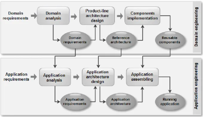
The development process of CBPL we propose (figure 1) is an integration of the development process of SPLs [4] and the component-based development process [5]. Unlike to the traditional SPL engineering, the base of core assets obtained from CBPL engineering relies mainly on software architecture (reference architecture, refinement of components and reusable components...). While, its difference compared to the traditional Component-based development is the introduction of variability management activity. Since variability is handled from the early stages of development, reusable components obtained from domain engineering process do not have to be adapted to the specific needs of final applications, which make the step of application assembly easier and faster.
Domain engineering consists of three activities that are Domain analysis, Product-line architecture design and Components implementation (Figure 1). The purpose of this sub-process is to produce the reusable core assets and to provide the effective means that help in using these core assets to build new products within the SPL. The main outputs of this process are: reference requirements, reference architecture and reusable components.
Figure 1: Component-Based Product Line engineering.
Application engineering consists in developing the final products, using the core assets and the specific requirements expressed by customers. This sub-process consists of three steps: Application analysis, Application architecture design for the specific application and finally Application assembling. Each step is facilitated by the reuse of the outputs from the previous process. The result of application engineering is an application ready to be used. 2.2. VARIABILITY MODELING IN CBPLs Variability management is a key activity that usually affects the degree to which a SPL is successful [6]. Variability refers to the ability of an artefact to be configured, customized, extended, or changed for use in a specific context [7], [8], [9]. This variability must be identified, represented, exploited, implemented, evolved, etc. – in one word managed – throughout software product line engineering [3].
After being identified, variability must be represented. The second step in managing variability is to model it in all software artefacts. Modeling variability is a technique used firstly to document the variability and secondly to reason about the variability. Its
main objectives are: to make the variability explicit in the early stages of the project, and to reduce the complexity related to variability management throughout the development process [2],[10].
For the modeling of variability in the architecture view, we have chosen to extend the component-based model IASA (Integrated Approach to Software Architecture) [11]. IASA was used to realize complex e-Government software system, and was proved as a clear and easy specification language to design at a high level of abstraction using Aspect Oriented approach [12] [13].
2.2.1. Architecture design with IASA
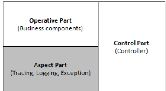
The design according to IASA approach uses a component-oriented process which proceeds by successive refinement. An IASA component is seen from the outside as a black-box that communicates with the external world through Ports [14], which define the services it can provide or require. The internal view of a primitive component is inaccessible, while the structure of a composite component is well defined, it consists of three parts: Operative Part, Aspect Part, and Control Part. Figure 2 sets out the basic notations of IASA.
Figure 2: Basic notations of IASA.
2.2.2. Variability modeling with IASA
Since IASA have not been developed to capture all types of variability explicitly, we propose to extend it in order to meet the needs of SPL engineering. We define three types of variability in architecture: Mandatory, Optional and choice.
Mandatory and Optional elements: Each element in the architecture can be mandatory or optional according to the context in which it will be used. In order to represent explicitly these types of variation, Components and Connectors are annotated by: «Mdr» and «Opt» which means respectively: Mandatory and Optional.
Considering that interfaces in the same component can be optional if they are not needed in some contexts, variability in interfaces is represented as follow:
Mandatory provided interface Mandatory required interface Optional provided interface Optional required interface
Choices: We distinguish between two types of choices:
1. Component choice: When there are a variety of implementations for the same component, the variable component is annotated by: «Choice» and related through the same interface to all its variants as shown in figure 3.
2. Connector choice: When a component is related to a variable set of components, the relation between these components becomes a connector annotated by: «Choice» and related with different interfaces to each variant as shown in figure 4.
Figure 3: Component choice.
The number of components that can be supported by the connector is expressed by a cardinality [n..m], such as:
n=m if the type of the relation is AND;
m>=n if the type of the relation is OR;
n=m=1 if the type of the relation is XOR or
Alternative.
Figure 4: Connector choice.
Figure 5: Business feature diagram for e-Meeting product line.
3. CASE STUDY: E-MEETING CBPL
In this section we apply our approach in a specific domain which is: E-Meeting applications. E-meeting applications exhibit an excellent solution to overcome the problems that can occur when organizing a face to face meeting namely: distance, costs and availability. Using online meeting technologies allow us to simplify the meeting organization processes, save time and displacement expenses.
The concept of meeting can be found in various fields. For instance: meetings for year-end deliberation, meetings of a Scientific Council, meetings of elected members of an APC3, APW4 or APN5, meetings of business leader, etc. E-meeting applications designed for these various types of meetings share many similarities and are distinguished by some particular aspects. It becomes very important to take advantage of similarities between these applications to develop a family of e-meeting applications. This family of product (SPL) once implemented is able to produce for each meeting type, the appropriate software in a very short time. In this case study we will focus on the component-based specification of the e-Meeting SPL. Next sub-sections describe the artefacts obtained from Domain analysis and Product-line architecture design steps.
3.1. Domain analysis
The goal of domain analysis is to extract and document the similarities and variations
3 An APC is the elected assembly which governs a commune (baladiyah).
4 An APW is the elected assembly which governs a wilaya (province).
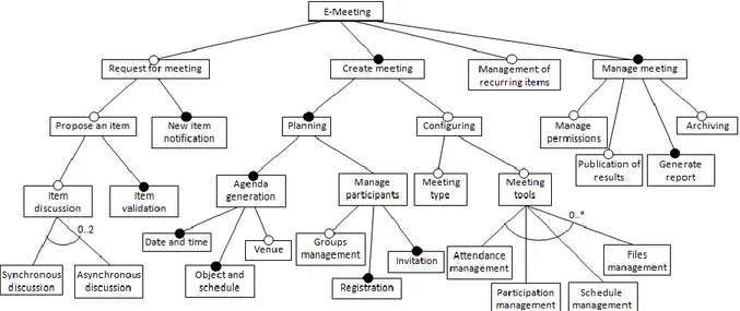
between the SPL members. To document the common and variable features of our product line, we have used the Feature Model. The Feature Model is the first language dedicated to the modeling of variability; it was first introduced in the Feature-Oriented Domain Analysis (FODA) method [15]. It has known a broad use in the field of SPLE, since it is a simple and easy to use language in comparison with other more complex modeling languages such as: UML and BPMN. The feature model is generally described by a hierarchy of the set of features of a system or what is called feature tree [4]. Figures 5 and 6 show a part of the feature model of our CBPL. For the notation, we must note that all of AND, OR, XOR variability types are expressed through cardinality (as shown in section 2) to avoid cluttering the diagram with more notations, for us cardinality is sufficient to represent all kinds of choices.
The constructed feature model is divided into three diagrams according to the type of features it includes: Business features, technical features, and implementation features. Features in the first diagram called Business features (Figure 5), represent the Business functionalities provided by the system. This diagram shows that the main features of an e-Meeting application are “Create meeting” and “Manage meeting”. Each e-Meeting application must allow at least the planning of a meeting and the generation of reports. However, in some cases a prior step can be needed before performing a meeting which is: the discussion of the meeting item, modeled by “Request for meeting” in the Feature diagram.
“Management of recurring items” feature can be included if the customer is interested to the history of previously treated items, there
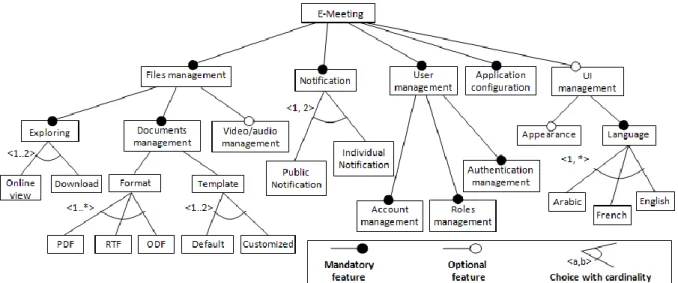
Figure 6: Technical feature diagram for e-Meeting product line.
“Configuring” a Meeting is an optional feature that consist in preparing the application by fixing the meeting type (video, audio, chat...), in addition to the needed tools to run a meeting according to the user’s requirements.
“Meeting tools” might include “Attendance management”, “Participation management”, “Schedule manage”… the application can eventually be extended by new tools if required.
Figure 7: Reference architecture of e-Meeting product line.
The second diagram Figure 6 represents the technical features; it means features that do not reflect the business aspect of e-Meeting applications. Technical features encompass features related to the application (configuration, UI management), features related to users (Accounts management, Roles management, Authentication), and features related to files (including: text, video
and audio files). Those features could be found in any e-Meeting application, but not all of them are mandatory.
The third diagram represents the implementation features of the system it means implementation details at lower levels. We do not show this diagram in the paper owing to space reasons.
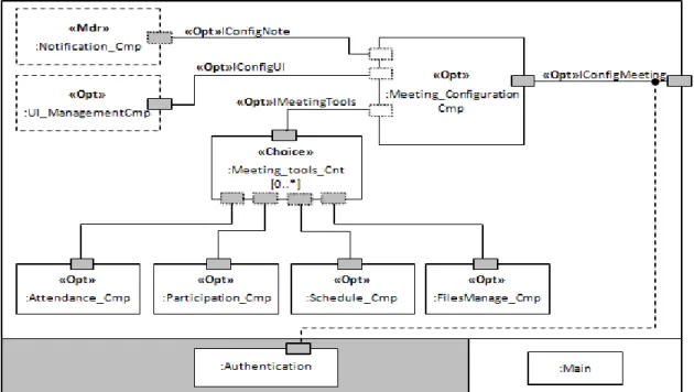
Figure 8: Variability model for “Meeting_Configuration” component.
3.2. Product-line architecture design
The purpose of Product-line architecture design is to establish the generic software architecture of the product line. Variability identified during domain analysis must be explicitly specified in the product-line architecture. To design the reference architecture of our composite SPL we have used the notation presented in section 2. The reference architecture of our e-Meeting product line is reported in figure 7. The mandatory components that must be included in each member of the SPL are annotated by «Mdr»(Meeting_Management,Meeting_Planni ng, Roles_Management…), while those which are optional are annotated by «Opt» (Items_Management,
Meeting_Configuration…).
Figure 8 shows the refinement of the “Meeting_Configuration_Cmp”. This latter can be connected to (can use) no or many tools components(Attendance_Cmp,Participation_C mp, Schedule_Cmp, FilesManage_Cmp). The choice connector “Meeting_tools_Cnt” allows us to represent this type of variability. The binding time6 of this variability can be: design,
6Is an attribute of variation points and/or variability
assembly, configuration or might be delayed until runtime, this leads developers to have more flexible applications and thus better customer satisfaction.
4. RELATED WORK
The most known approaches that integrate Software Product Line engineering and Component-based engineering are: Kobra [17] and Koala [18] [19]. The basic goal of Kobra is to provide a systematic approach to the development of component-based application frameworks. Nevertheless, Kobra approach interest to the internal structure of components for which it uses UML modeling. Therefore, this approach cannot be compared to ours. Koala is a component model based on an architectural description language used to build a large diversity of products from a repository of components.Its aim is to manage the growing complexity and diversity of software in consumer electronics products. Various concepts are used in the koala components models, like interfaces, connectors, subcomponents and compound decisions to later stages in the software
components. Koala allows the modeling of variability related to interfaces (optional interfaces) and connections between interfaces (switch). However, the model proposed by Koala does not cover all types of variability that can be found and must be explicitly defined in a SPL, such as: mandatory or optional components, AND, OR, XOR relations… Furthermore, Koala consider variability binding only at configuration time, while SPL engineering allows several binding times, according to the context, ranging from design to configuration and runtime [16]. 5. CONCLUSION
The work presented in this paper aims to reach a high level of reuse that can be obtained through the integration of two approaches: Software product lines and Component-based development. Each of these approaches promotes reuse at different granularity levels. Component-based development supplies technologies for reuse in the small, while Software product line approach intends reuse in the large. Putting them together allow us to reach large scale reuse and flexibility at the same time. Moreover, Component-based development can overcome the lack of maturity in SPL engineering by providing efficient technologies of development.
Since our approach needs more space to be well define, this paper presented the outlines of the proposed approach, mainly: the development process and the Component-based model. The paper presents also a case study for an ambitious field (e-Meeting) aiming to validate the proposed approach. The designed e-Meeting reference architecture represents a framework for all foreseeable e-Meeting applications and can be extended to cover specific requirements if needed. Since, software can be quickly derived from a CBPL by the simple composition of existing components; the activity of deriving new members in a CBPL can be greatly automated. The automation of applications derivation step is an important perspective of our work. 6. REFERENCES
[1] M. N. Linda, C. C. Paul, “A Framework for Software Product Line Practice”, Version 5.0 (online), http://www.sei.cmu.edu/. [2] C. Jean, “Les lignes de produits logiciels
Réutilisation et variabilité ”, Publication périodique de Smals, Juin 2009.
[3] F. van der Linden, S. Klaus, R. Eelco, “Software Product Lines in Action: The Best Industrial Practice in Product Line Engineering”, Springer, 2007.
[4] P. Klaus, B. Günter and F. van der Linden, Software Product Line Engineering: Foundations, Principles, and Techniques, Springer, 2005.
[5] S. Roger Pressman, “Software engineering: a practitioner’s approach”, Edition: 5, McGraw-Hill Higher Education, June 2000. [6] L. Chen, M.A. Babar, A. Nour, “Variability
Management in Software Product Lines: A Systematic Review,” SPLC, San Francisco, California, 2009.
[7] B. Felix and C.C. Paul, “Variability in Software Product Lines”, technical report CMU/SEI, 2005.
[8] G. Jilles van, B. Jan, S. Mikael , “On the Notion of Variability in Software Product Lines”, WICSA, 2001.
[9] S. Mikael, G. Jilles van, and B. Jan, “A taxonomy of variability realization techniques”, Software Practice and Experience, 2005.
[10] M. Andreas, P. Klaus, H. Patrick, S. Pierre-Yves, S. Germain, “Disambiguating the Documentation of Variability in Software Product Lines: A Separation of Concerns, Formalization and Automated Analysis”, 15th IEEE International In Requirements Engineering Conference, 2007.
[11] B. Djamal, “The Integrated Approach to Software Architecture”, Ph.D. Thesis, Ecole Supérieure d’Informatique, Oued Smar, Algiers (in French), 2009.
[12] B. Djamal, S. Abdelfettah, “The Design of an eGovernment Application Using an Aspect Oriented Software Architecture Approach”, AOSA conference, 2009. [13] B. Djamal, H. Abderrezak, S. Abdelfettah,
“The Design of A Complex Software System Using A Software Architecture Approach”, ACIT, 2008.
[14] B. Djamal, T. Khammaci, H. Abderrezak, “A new approach for component’s port modeling in software architecture”, In: Journal of System and Software, Elsevier, Volume 83 Issue 8, August, 2010.
[15] K. Kang, S. Cohen, J. Hess, W. Nowak, and S. Peterson, “Feature- Oriented Domain Analysis (FODA) Feasibility Study,” Technical Report CMU/SEI-90-TR-21, 1990. [16] C. Rafael, B. Jan, “Binding Time and Evolution, Systems and Software Variability Management”, pp 57-73, Springer, 2013. [17] A. Colin, B. Joachim, M. Dirk,
“Component-Based Product Line Development: The KobrA Approach”, software Product Line Conference, 2000.
[18] O. Rob van, “The Koala component model for consumer electronics software”, Philips Research Eindhoven, IEEE Computer 33(3), MAR 2000.
[19] A. Timo, S. Timo, and M. Tomi, “A Koala-Based Approach for Modelling and Deploying Configurable Software Product Families”, PFE-5, 2004.