HAL Id: hal-00712231
https://hal.archives-ouvertes.fr/hal-00712231
Submitted on 26 Jun 2012
HAL is a multi-disciplinary open access
archive for the deposit and dissemination of
sci-entific research documents, whether they are
pub-lished or not. The documents may come from
teaching and research institutions in France or
abroad, or from public or private research centers.
L’archive ouverte pluridisciplinaire HAL, est
destinée au dépôt et à la diffusion de documents
scientifiques de niveau recherche, publiés ou non,
émanant des établissements d’enseignement et de
recherche français ou étrangers, des laboratoires
publics ou privés.
The clapping book: Wind-driven oscillations in a stack
of elastic sheets
Peter Buchak, Christophe Eloy, Pedro M. Reis
To cite this version:
Peter Buchak, Christophe Eloy, Pedro M. Reis. The clapping book: Wind-driven oscillations in a
stack of elastic sheets. Physical Review Letters, American Physical Society, 2010, 105, pp.194301.
�10.1103/PhysRevLett.105.194301�. �hal-00712231�
P. Buchak1
, C. Eloy2
, and P. M. Reis3,4∗
1
Department of Mathematics, Massachusetts Institute of Technology (MIT), Cambridge, MA 02139, USA
2
IRPHE, CNRS & Aix-Marseille Universit´e, 49 rue Joliot Curie, 13013 Marseille, France
3
Department of Mechanical Engineering, MIT, Cambridge 02139, USA.
4
Department of Civil and Environmental Engineering, MIT, Cambridge 02139, USA. We present a hybrid experimental and theoretical study on the oscillatory behavior exhibited by a system of multiple thin sheets under aerodynamic loading. Our clapping book consists of a stack of paper, clamped at the downstream end, placed in a wind tunnel with steady flow. As individual pages lift off, they accumulate onto a bent stack held up by the wind. The book collapses shut once the elasticity and weight of the pages overcome the aerodynamic force, and the process repeats periodically. We develop a theoretical model that predictively describes this periodic clapping process.
PACS numbers: 46.40.Jj, 46.70.De, 47.63.mc
There has been much recent interest in the coupling of a flexible solid structure and fluid flow. The challenge lies in the strong nonlinear coupling between the fluid dynamics and the potentially large deformations of the structure. This arises in the classic contexts of vortex-induced vibrations (VIV) [1], wind loading of bridges and buildings [2], and in printing [3]. Instances in biol-ogy are also ubiquitous, including the dynamics of swim-ming [4, 5] and flying [6], snoring [7], and flow in flex-ible tubes [8]. Model systems have been paramount in understanding the governing physics, where the flapping flag [9] has become the canonical problem. Arrays of multiple flexible objects in fluid flow have particular bio-logical significance, such as in locomotion of microorgan-isms [10], wind loading in canopies of flexible plants [11], and mixing and transport of nutrients and pollutants by aquatic plants in wetlands [12]. In the context of model systems, a few recent studies have focused on arrays of multiple flag-like objects [13]. However, the predictive understanding of systems of multiple sheets under flow in other geometries remains challenging.
Here, we introduce a novel model system, the clapping book. In our experiments the book is a stack of 150 pages of paper (Hammermill), each of length L = 17.0 cm, width W = 2.8 cm, and thickness h = 110 µm. Each page has mass per unit length ρphW = 0.021 g/cm and
bending stiffness BW = 8.2 × 10⁻⁶N m2
, where ρpis the
paper’s density, B = Eh3
/12(1 − ν2
) the bending mod-ulus, E the Young’s modmod-ulus, and ν the Poisson ratio. We clamp the pages at one end and place the book in the 30 cm × 30 cm test section of a wind tunnel, with the clamped end downstream. The working range for wind speeds is between 2m/s and 20 m/s. The book is imaged from the side using a Sony HDR-SR5 digital camcorder, at 120 frames per second. A sequence of representative
frames of the clapping process is presented in Fig. 1a-e. The pages lift off (Fig. 1a-d) and form a bent stack of paper held up by the wind. As pages accumulate, this elevated stack thickens and moves progressively further upstream. Eventually the book claps shut and this pro-cess restarts (Fig. 1e), resulting in continuous oscillations with a well-defined period. It is noteworthy that these oscillations are controlled by the interaction of multiple elastic sheets and occur on a time scale much slower than the natural period of each sheet. In what follows, we de-velop a theoretical model to explain this behavior quan-titatively and perform a series of detailed comparisons with our experiments. We consider the large elastic de-formations, the interaction between the pages, and their coupling with the flow.
We model each elevated page as an inextensible
elas-t=0.04s t=0.85s t=1.68s t=0.45s t=2.08s b) a) c) e) f) d) U clamp e) s=L s=0 s U L θ clamp n t U clamp e x e y flat pages bent stack
FIG. 1: (a-e) Representative photographs of the clapping book at selected times during a single period. (f) Schematic diagram of the system.
2
tic beam of dimensions h ≪ W ≪ L whose motion is confined to the xy plane (Fig. 1f). Its shape can therefore be represented by x(s, t), with unit tangent xs = t = (cos θ, sin θ) and counterclockwise normal n. Its evolution is governed by the relation between curva-ture and torque and the angular and linear momentum equations, which can respectively be written in dimen-sionless form as [14],
θs = Γ, (1)
Iθtt = Γs+ n · F, (2)
xtt = Fs+ Kn − ∆ey, (3) where the arclength s and position x are scaled by L, and time t bypρphL4/B. The z-component of the internal
torque (Γ), the internal force (F), and the aerodynamic force per unit length (K) are scaled by BW/L, BW/L2
and BW/L3
, respectively. This non-dimensionalization results in two dimensionless parameters, I = h2
/12L2
and the elastogravity number ∆ = ρpghL 3
/B, which ac-counts for the relative weight of the pages with respect to their bending rigidity. The pages are thin relative to their length, I ≪ 1, and the corresponding term in Eq (2) is therefore neglected, yielding a model equivalent to the flag in [9]. At the clamped end of the beam, the posi-tion is fixed, x|s=0 = 0, and its tangent is horizontal,
θ|s=0= 0. At the free end, the internal torque and force
must vanish, i.e. Γ|s=1= 0 and F|s=1= 0, respectively.
To describe the flow around the pages, we focus on the slender body limit [15] with a far field uniform wind velocity −U ex. Viscous drag can be neglected since the
Reynolds number based on page length ranges from 4 × 10⁴
to 2 × 10⁵
. In the wind’s frame of reference, the beam’s shape is given by X(s, t) = x(s, t) + U texand the
flow is determined entirely by the normal component of the beam’s velocity, V = n · Xt= n · xt+ U n · ex. For our
regime of interest, the speed of the pages is much slower than the speed of the flow itself, so the time derivative term is neglected for simplicity.
We consider two components of the external aerody-namic force on the beam, the resistive and the reactive forces. The resistive force on an element of the beam is the drag experienced by a flat plate moving in the di-rection of its normal, with magnitude per unit length F1=
1 2CdρaV
2
W , where ρa is the density of air and Cd
is a drag coefficient that must be determined experimen-tally. Assuming the flow reaches a steady state faster than the beam moves, any contribution from the un-steadiness of the flow can be ignored. The reactive force arises as the fluid accelerates to follow the shape of the beam. Following [5], we take the flow locally to be the potential flow induced by a flat plate moving in the direc-tion of its normal. This flow has momentum P = ρaAV n,
where ρaA is the beam’s added mass, with A = π(W/2)2
being the area of its circumscribing circle. The change in the fluid momentum at a fixed point in the moving frame
is Pt− (U ex· t)Ps, the −n component of which gives the
magnitude of the reactive force (per unit length) on the beam, F2 = −ρaA(Vt− (U cos θ)Vs). Again, the
rela-tively low speed of the pages allows the time derivative term to be ignored.
The total aerodynamic force on the beam is the sum of the resistive and reactive forces, F1+ F2. This can be
expressed in dimensionless form as
K = 1 2CdCysin 2 θ − π 4 λ Cycos 2 θdθ ds, (4) where Cy = ρaU2L3/B is the Cauchy number, the
di-mensionless ratio of aerodynamic force ρaU2W L to
bend-ing force BW/L2
, and λ = W/L is the aspect ratio of the beam.
Our model has four parameters, ∆, λ, Cy, and Cd.
The drag coefficient, Cd, is the only parameter that must
be determined by fitting (once and for all) to experi-ments (described below). The approximate ranges of the other parameters in our experiments are 0.1 < ∆ < 20, 0.1 < λ < 0.5, and Cy < 60. Given values for these
parameters, the static shape of a beam at equilibrium in the wind can be computed by solving Eqs. (1-4) with the time derivative terms dropped. In Fig. 2a-c, we present
(b) (a) U (c) Exp. Model (d) Fig. 2(a) Fig. 2(b) Fig. 2(c) 0.05 0.1 0.15 0.2 0.25 0 5 10 15 20 Sheet length, L (m) C ri ti ca l w in d sp e e d , U * (m/
s) Acetate ExperimentVPS Experiment Acetate Model VPS Model
(U,L) in Fig. 2(a), (b) & (c)
FIG. 2: (a,b,c) Photographs of a single acetate sheet (solid
lines), with L = 15.0 cm, W = 2.9 cm, ρphW = 0.114 g/cm,
and BW = 2.4 × 10⁻⁴N m2
, superimposed with predicted shape (dashed lines). Flow speeds were (a) 11.1, (b) 8.5, and (c) 6.8 m/s. For all static shape calculations, we use a spa-tial resolution of 1000. (d) Experimental and predicted (with
Cd = 1.76) critical wind speed versus length for two
materi-als: acetate strip with W = 3.0 cm, ρphW = 0.118 g/cm, and
BW = 2.6 × 10⁻⁴N m2
; vinylpolysiloxane (VPS) strip with
W = 2.2 cm, ρphW = 2.04 g/cm, and BW = 2.3×10⁻⁴N m
2
, with paper on its front surface. Also shown (×) are parameter values for the photographs in (a), (b), and (c).
photographs of the experimental shapes of a single elas-tic sheet taken at three wind speeds using a Nikon digital SLR camera, and superimpose the shapes predicted by our model, showing excellent agreement.
In the experiments, as U is decreased, we observe that there is a critical wind speed below which a given sheet can no longer be supported. In Fig. 2d, we show mea-surements of this speed for a strip of acetate and a strip of vinylpolysiloxane (VPS), as L is varied. Similarly, for given values of ∆, λ, and Cd, Eq. (1-4) fail to have a valid
equilibrium solution when Cy is below a critical value
C∗
y. Hence, from the definition of Cy, a critical wind
speed U = U∗ is predicted. We compare the
experimen-tally measured critical wind speeds with those predicted by our model (Fig. 2d), where the drag coefficient Cd
is treated as the single fitting parameter. In the subse-quent calculations we use the the average value that best fits each material, Cd = 1.76 ± 0.03, which is consistent
with previously reported experimental measurements of the drag coefficient for a flat plate [16].
Having presented a model for a single wind-loaded sheet, we return to the clapping book to understand its periodic behavior. At any one time, we consider some of the book’s pages to be lifted up, forming a stack bent by the wind, while the rest remain flat. When the elevated stack contains more pages than the wind can support, the book claps shut. We proceed by separately considering three aspects of the process: (i) page accumulation, (ii) loss of support of the bent pages, and (iii) the subsequent collapse.
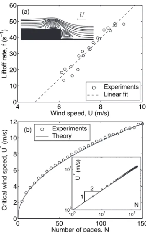
To help in describing page accumulation, a schematic diagram of the expected flow profile over the flat stack is sketched in Fig. 3a, with recirculation zones shown ahead of the step and on the surface of the top page. This geometry is known as the forward-facing step and has been studied both experimentally [17] and compu-tationally [18]. A detailed analysis of the flow would involve determining the locations of flow separation and reattachment, a challenging endeavor that goes beyond the scope of our study. Instead, we proceed by deducing an empirical relation for the page liftoff rate. We focus on the regime in which the wind speed is high enough that the pages lift off continuously. In Fig. 3a, we present ex-perimental measurements of the dependence of the liftoff rate, f , on wind speed for a particular book. We find that f is well described by the linear relationship,
f = β(U − U0), (5)
with β = 12.5±0.8 m−1and U0= 4.9±0.2 m/s (Fig. 3a).
We proceed by determining the maximum number of pages that the wind can support, using the equilibrium model for a beam introduced above, Eq. (1-4), after drop-ping the time derivatives. The elevated pages are treated as a single beam, and we assume that the pages slide against each other without friction. As such, the bend-ing energy of the stack of elevated pages is the sum of the
4 6 8 10 0 10 20 30 40 50 60 Wind speed, U (m/s) L if to ff ra te , f (s −1 ) U 0 50 100 150 0 2 4 6 8 10 12 Number of pages, N C ri ti ca l w in d sp e e d , U * (m/ s) 100 101 102 100 101 N U * (m/ s) 1 2 (a) (b) Experiments Linear fit Experiments Theory
FIG. 3: (a) Experimental page liftoff rate averaged over 10 oscillations for the paper book. The dashed line is the liftoff rate given by Eq. (5). Inset: Sketch of expected flow profile. (b) Critical wind speed measured for an elevated stack of N pages. The solid line is calculated using Eq. (6). Inset: log-log version of the plot.
bending energies of the individual pages. Thus, if ρphW
and B characterize a single page, the elastic beam repre-senting the entire elevated stack of N pages has mass per unit length N ρphW and bending stiffness N B [19]. We
note that both parameters ∆ and λ are then independent of N . Hence, since the model’s prediction for C∗
ydepends
only on ∆ and λ, this prediction should be unique for a particular book, regardless of how many pages have been lifted up. Using this C∗
y, the definition of Cy yields a
relation between the number of pages in a stack, N , and the critical wind speed, U∗:
C∗ y =
ρaU∗2L3
N B . (6)
For our book, the model gives C∗
y = 18.5, from
which the critical wind speed can be calculated, U∗ =
q
N BCy∗/ρaL3. In Fig. 3b (and inset), we show that
this prediction is in excellent agreement with the experi-mentally measured critical wind speeds and validates our description of the behavior of multiple pages. Conversely, for a given wind speed U , we use Eq. (6) to obtain the number of pages, N∗, for which U is the critical speed.
This is the maximum number of pages this wind speed can support.
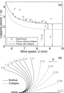
4 (b) (a) U N* f Tc T Buildup Collapse clamp 0.9s 1.2s1.5s 1.8s 2.1s2.4s 3.11s 3.21s 3.25s 3.29s 3.32s 2.7s 6 7 8 9 10 0 1 2 3 4 Wind speed, U (m/s) C la p p in g p e ri o d , T (s) Experiments Theory: without collapse Theory: with collapse
FIG. 4: (a) Experimentally measured clapping period as a function of wind speed compared with the prediction from Eq. (7). The dashed line is the first term of Eq. (7); the solid line incorporates the collapse time (spatial resolution is 50,
dimensionless time step is 5 × 10⁻⁸). (b) Simulated sequence
of the clapping process (U = 6 m/s, t = 0 s at the start of accumulation). The solid and dashed lines correspond to accumulation and collapse, respectively.
Once this maximum number of pages is exceeded, sta-bility is lost and the bent stack collapses. We simulate the collapsing stack of pages as a beam using the full time-dependent form of Eq. (1-4), supplemented with the in-extensibility condition xtts= ttt. To account for the
mo-mentum of the pages when collapse begins, we start the simulation with the equilibrium shape P/4 time before the maximum number of pages has accumulated, with no initial velocity. Here P = 2π/m2
is the dimensionless period of the first mode of an unforced beam, with the constant m = 1.88 given by Rayleigh [20]. In the simula-tions, as in the experiments, we observe the entire page to become horizontal nearly simultaneously, and denote the time at which this occurs Tc. For simplicity, we use
the collapse simulation run at the middle wind speed, finding that the collapse time differs for the minimum and maximum wind speeds by less than 0.1 s.
Having described the accumulation and collapse of the pages, these results can be combined to calculate the to-tal clapping period, which is a representative and readily quantifiable feature of the oscillatory clapping process. The duration of accumulation can be taken to be the maximum number of pages that can be supported, N∗
from Eq. (6), divided by the rate at which pages accu-mulate, f from Eq. (5). This is added to the duration of
collapse, Tc, to give the complete clapping period,
T = N∗
f + Tc. (7) In Fig. 4a we show the measured clapping period for a book as a function of U , which is in excellent agreement with our theoretical prediction. Representative calcu-lated page shapes over one period are shown in Fig. 4b and compare well with the photographs in Fig. 1.
In summary, we have introduced a novel system, the clapping book, that exhibits regular oscillations con-trolled by the interaction of multiple thin sheets and flow. This system was a priori challenging to model because of the large-amplitude deformation of the sheets and their interaction with each other and with the wind. Using a model for elastic beams in high Reynolds number flow, we combined descriptions of each stage of the clapping pro-cess: page accumulation, loss of stability, and dynamic collapse. We were thereby able to calculate the clap-ping period in good agreement with our experiments. We hope that the rationalization of this model system will provide insight into other problems involving multi-ple flexible structures and flow, which are abundant in the natural world.
We thank Saba Mohsin and Jillian James for techni-cal assistance, John Bush, Eitan Grinspun, and Fran¸cois Gallaire for discussion, and Jos´e Bico for suggesting the title. C. Eloy acknowledges funding by the ANR under the project ANR-06-JCJC-0087.
[1] C.H.K. Williamson and R. Govardhan, Annu. Rev. Fluid Mech. 36 413-55 (2004).
[2] J. Holmes, Wind Loading of Structures, Taylor & Francis (2007).
[3] Y. Watanabe, S. Suzuki, M. Sugihara, and Y. Sueoka, J. Fluids and Structures, 16(4), 529-542 (2002).
[4] G. Taylor, Proc. Roy. Soc. A, 214, 1117, 158-183 (1952). S. Spagnolie and E. Lauga, Phys. Fluids 22 031901 (2010).
[5] Lighthill, J. Fluid Mech., 9, 2, (1960).
[6] D. Tam, J. W. M. Bush, M. Robitaille, and A. Kudrolli, Phys. Rev. Lett. 104, 184504 (2010).
[7] L. Huang, J. Acoust. Soc. Am., 97(6):3642-8 (1995). [8] T. Pedley and X. Luo, Theoret. Comput. Fluid Dynamics
10: 277-294 (1998).
[9] S. Alben and M. J. Shelley, Phys. Rev. Lett. 100, 074301 (2008).
[10] C. Brennen and H. Winet, Ann. Rev. Fluid Mech., 9: 339-98 (1977); K. Drescher, K. C. Leptos, I. Tuval, T. Ishikawa, T. J. Pedley, and R. E. Goldstein, Phys. Rev. Lett. 102, 168101 (2009).
[11] C. Py, E. de Langre, and B. Moulia, J. Fluid Mech. 568, 425-449 (2006).
[12] M. Ghisalberti and H.M. Nepf , J. Geophys. Res. 107, 3 (2002).
[13] L. B. Jia, F. Li, X. Z. Yin, and X. Y. Yin, J. Fluid Mech.,
Lett. 100, 228104 (2008); L. Schouveiler and C. Eloy, Phys. Fluids 21, 081703 (2009); S. Michelin and S. Smith, J. Fluids and Structures 25, 1136-1157 (2009); L. Zhu, J. Fluid Mech., 635, 455-475 (2009); G. J. Elfring and E. Lauga, Phys. Rev. Lett. 103, 088101 (2009). L. Ristroph and J. Zhang, Phys. Rev. Lett. 101, 194502 (2008). [14] L. D. Landau and E. M. Lifshitz, Theory of Elasticity
(1959), section 19. B. Coleman, E. Dill, M. Lembo, Z. Lu, and I. Tobias, Arch. Rational Mech. Anal. 121 (1993) 339-359.
[15] L. Schouveiler, C. Eloy, and P. Le Gal, Phys. Fluids 17, 047104 (2005).
[16] D. Lisoski, “Nominally two-dimensional flow about a
normal flat plate”, Ph.D. Thesis, California Institute of Technology (1993).
[17] M. Sherry, D. Jacono, J. Sheridan, R. Mathis, and I. Marusic, Sixth International Symposium on Turbulence and Shear Flow Phenomena (2009).
[18] D. Wilhelm and L. Kleiser, J. Scientific Computing, 17, 1-4 (2002).
[19] If the pages were to stick together without sliding, the beam’s thickness would scale with N , resulting in a bend-ing stiffness that scales with N3
.
[20] J. W. S. Rayleigh, The Theory of Sound, Volume 1, Chapter VIII (1878).