Publisher’s version / Version de l'éditeur:
Vous avez des questions? Nous pouvons vous aider. Pour communiquer directement avec un auteur, consultez
la première page de la revue dans laquelle son article a été publié afin de trouver ses coordonnées. Si vous n’arrivez pas à les repérer, communiquez avec nous à PublicationsArchive-ArchivesPublications@nrc-cnrc.gc.ca.
Questions? Contact the NRC Publications Archive team at
PublicationsArchive-ArchivesPublications@nrc-cnrc.gc.ca. If you wish to email the authors directly, please see the first page of the publication for their contact information.
https://publications-cnrc.canada.ca/fra/droits
L’accès à ce site Web et l’utilisation de son contenu sont assujettis aux conditions présentées dans le site
LISEZ CES CONDITIONS ATTENTIVEMENT AVANT D’UTILISER CE SITE WEB.
The 45th International Conference of Metallurgists(COM 2006) [Proceedings], 2006-10
READ THESE TERMS AND CONDITIONS CAREFULLY BEFORE USING THIS WEBSITE.
https://nrc-publications.canada.ca/eng/copyright
NRC Publications Archive Record / Notice des Archives des publications du CNRC :
https://nrc-publications.canada.ca/eng/view/object/?id=f14881dd-a7af-48d3-82b4-760242cc4849 https://publications-cnrc.canada.ca/fra/voir/objet/?id=f14881dd-a7af-48d3-82b4-760242cc4849
NRC Publications Archive
Archives des publications du CNRC
This publication could be one of several versions: author’s original, accepted manuscript or the publisher’s version. / La version de cette publication peut être l’une des suivantes : la version prépublication de l’auteur, la version acceptée du manuscrit ou la version de l’éditeur.
Access and use of this website and the material on it are subject to the Terms and Conditions set forth at
Flow Visualization of Newtonian and Non-Newtonian Fluids in High Pressure Die Casting
FLOW VISUALIZATION OF NEWTONIAN AND NON-NEWTONIAN FLUIDS IN HIGH PRESSURE DIE CASTING
Martin Forté1, Dominique Bouchard2 and André Charette3 1
Formerly with the Aluminium Technology Centre and Université du Québec à Chicoutimi. Presently with the Arvida Research and Development Centre
1955, Mellon Blvd., P.O. Box 1250 Jonquière, QC, Canada, G7S 4K8
martin.forte@alcan.com
2
Aluminium Technology Centre 501, Boul. Université, Chicoutimi, QC, Canada, G7H 8C3 3
Université du Québec à Chicoutimi (UQAC) 555, Boul. Université,
Chicoutimi, QC, Canada, G7H 2B1
ABSTRACT
A transparent replica of a casting die was built to achieve a better understanding of the filling mechanisms of aluminum in high pressure die casting. Water and tomato paste were respectively used as analogues for the Newtonian liquid aluminum and the non-Newtonian semi-solid aluminum. The transparent die was installed on an industrial casting press and filling was filmed with a high-speed camera. Differences between the Newtonian and non-Newtonian fluids are presented and discussed.
INTRODUCTION
High pressure die casting (HPDC) is often the process of choice to produce components with complex shapes at high volumes. To this effect, close to 70% of all aluminum castings are obtained with this process [1]. These castings are conventionally produced from liquid aluminum alloys but a limitation to their wider use as structural parts is the large number of defects, particularly porosity, that are usually present. These defects mainly originate from gas entrapment during filling and solidification shrinkage during solidification [2]. A strategy that can be used to improve the integrity of castings is to inject an aluminum alloy in a partially solidified condition. Porosity from gas entrapment can then be reduced due to the improved die filling conveyed by the more viscous fluid. Shrinkage porosity is also reduced since the castings are obtained from a partially solidified alloy.
In this work, the differences in the die filling behaviors between liquid and semi-solid aluminum were visualized with physical modeling. Water and tomato paste were respectively used as the analogue fluids for the Newtonian liquid aluminum and non-Newtonian semi-solid aluminum. A transparent die was fabricated and the filling sequence was filmed with a high speed camera.
THEORY
Liquid aluminum is a Newtonian fluid, e.i., the viscosity, μ , (the ratio of shear stress to shear rate) is constant with a value of approximately ~0.002Pa⋅s[3]. With semi-solid aluminum, the shear stress to shear rate ratio is not constant and the fluid belongs to the family of non-Newtonian fluids. High pressure die casting produces a large amount of shearing during die filling and the viscosity of the fluid therefore varies over a wide range. The fluid exhibits a thixotropic behavior whereby the non-Newtonian viscosity decreases with time under constant shearing. This is caused by disagglomeration and morphological changes in the solid particles [4] but this effect is difficult to quantify in HPDC since mold filling typically occurs in less than half a second. Semi-solid aluminum also exhibits a shear thinning behavior [4] where the non-Newtonian viscosity,η , decreases with shear rate and may be expressed with a power law model.
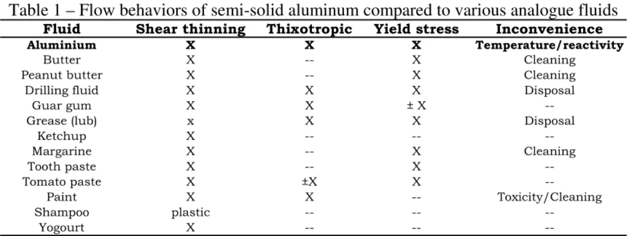
Aluminum chemically reacts with most materials and the visualization of its flow cannot be carried out using a die transparent to the visible light spectrum. However, a physical model can be constructed whereby the aluminum is replaced by a less chemically reactive fluid to simulate its flow. For liquid aluminum, water can conveniently be used [5,6] and for semi-solid aluminum, tomato paste was selected after a comparison with other fluids, as summarized in Table 1. Criteria in the selection were the room temperature rheological properties and the ease of its use and disposal. The utilization of tomato paste to simulate the flow of semi-solid aluminum has also been reported elsewhere [7].
Table 1 – Flow behaviors of semi-solid aluminum compared to various analogue fluids
Fluid Shear thinning Thixotropic Yield stress Inconvenience
Aluminium X X X Temperature/reactivity
Butter X -- X Cleaning
Peanut butter X -- X Cleaning
Drilling fluid X X X Disposal
Guar gum X X ± X
--Grease (lub) x X X Disposal
Ketchup X -- -- --Margarine X -- X Cleaning Tooth paste X -- X --Tomato paste X ±X X --Paint X X -- Toxicity/Cleaning Shampoo plastic -- -- --Yogourt X -- --
--Figure 1 illustrates the apparent viscosity as a function of shear rate for the Heinz® Pure Tomato Paste and the A356 aluminum at a solid fraction close to 0.5. It is seen that the macroscopic shear thinning behavior of the A356 alloy is fairly well reproduced by the tomato paste. The apparent viscosity of the tomato paste was characterized with a Couette rheometer (PAAR Physica MCR 500 with CC 27 cylinders), at shear rates that ranged from 0.001 to 1000 s-1 and yielded the K and n parameters that are shown in the Figure. For the semi-solid aluminum, these parameters were taken from the work of Nguyen et al. [8] and Orgeas [9].
0 2 4 6 8 10 10 100 1000 10000
Shear rate (s-1)
Apparent Viscosity (Pa.
s)
Tomato paste (K=113 n=0.27) fs=0.50 (K=60.4 n=0.34) fs=0.52 (K=93.5 n=0.32)
Figure 1 – Apparent viscosity as a function of shear rate for the semi-solid A356 alloy and the Heinz® Pure Tomato Paste
To obtain a dynamic similarity between the flow of aluminum and an analogue fluid, the magnitude of forces at similarly located points in each system must have fixed ratios [10]. In HPDC, the flow is mainly affected by inertia and viscous forces whose ratio defines the Reynolds number. The flow of semi-solid aluminum is also affected by its yield stress, whose ratio with the viscous stress defines the Bingham number. The yield stress however varies considerably with the solid fraction [11] and scaling
difficulties arise from the simultaneous consideration of Reynolds and Bingham numbers [12]. The dynamic similarity in this work was therefore solely based on the Reynolds number and experiments with water were carried out at values of ~1·104 and ~5·104 while those with the tomato paste were at 10 and 100. The scaling ratio between the model and the prototype was also set to 1:1.
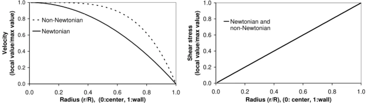
Some of the differences between Newtonian and power law non-Newtonian fluids can be viewed by considering a steady and fully developed laminar flow in a circular tube with no slip at the boundary. In Figures 2 to 5, differences in velocity, shear stress, shear rate and viscosity are illustrated. The equations utilized in these calculations are listed in Table 2 and the symbols are defined in the Nomenclature.
0.0 0.2 0.4 0.6 0.8 1.0 0.0 0.2 0.4 0.6 0.8 1.0
Radius (r/R), (0:center, 1:wall)
V eloci ty (loca l va lue/m ax valu e) Non-Newtonian Newtonian 0.0 0.2 0.4 0.6 0.8 1.0 0.0 0.2 0.4 0.6 0.8 1.0
Radius (r/R), (0: center, 1:wall)
Shea r stres s (lo cal v alue /ma x va
lue) Newtonian and non-Newtonian
Figure 3 – Shear stress profile for the Newtonian and non-Newtonian fluids Figure 2 – Velocity profiles for the
Newtonian and non-Newtonian fluids
0.0 0.2 0.4 0.6 0.8 1.0 0.0 0.2 0.4 0.6 0.8 1.0 0.0 0.1 0.2 0.0 0.1 0.2
Radius (r/R), (0:center, 1:wall)
Vi scosi ty (l ocal value / max val ue) Non-Newtonian
Radius (r/R), (0:center, 1:wall)
Sh ear ra te (loca l va lue/m ax v alue ) Non-Newtonian Newtonian
Figure 4 – Shear rate profiles for the Newtonian and non-Newtonian fluids
Figure 5 – Non-Newtonian vis-cosity profile
In Figure 2, the velocity of the non-Newtonian fluid is relatively constant near the center of the tube but has a steep gradient near the wall. For a given average velocity, the non-Newtonian fluid will have a lower maximum velocity than the Newtonian one. In Figures 3 and 4, it is seen that shear stress and shear rate are at the maximum at the wall of the tube. In Figure 5, the non-Newtonian viscosity varies over a large range but most of the variation is concentrated near the center of the tube.
Table 1. Velocity, shear stress, shear rate and viscosity equations for the Newtonian and power law non-Newtonian fluids flowing in a circular tube [13].
Newtonian fluid Non-Newtonian power law fluid
Velocity
( )
⎥ ⎥ ⎦ ⎤ ⎢ ⎢ ⎣ ⎡ ⎟ ⎠ ⎞ ⎜ ⎝ ⎛ − Δ = 2 2 1 4 R r L R P vz μ( )
( )
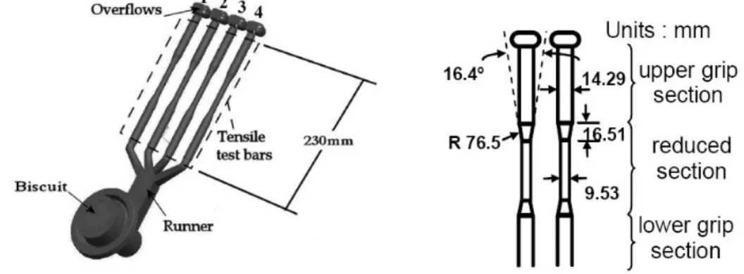
( ) ⎥ ⎥ ⎦ ⎤ ⎢ ⎢ ⎣ ⎡ ⎟ ⎠ ⎞ ⎜ ⎝ ⎛ − + ⎥⎦ ⎤ ⎢⎣ ⎡ Δ = +1 1 1 1 1 1 2 n n z R r n R KL R P v Shear stress L r P rz ⎟ ⎠ ⎞ ⎜ ⎝ ⎛ Δ = 2 τ r L P rz ⎟ ⎠ ⎞ ⎜ ⎝ ⎛ Δ = 2 τ Shear rate L r P ⎟⎟ ⎠ ⎞ ⎜⎜ ⎝ ⎛ Δ − = μ γ 2 & n K r L P 1 2 ⎥⎦ ⎤ ⎢ ⎣ ⎡ ⎟ ⎠ ⎞ ⎜ ⎝ ⎛ Δ − = γ& cst = μ = n−1 Kγ η & Viscosity EXPERIMENTAL SET-UPA schematic of the test part that was modeled is illustrated with its dimensions in Figure 6. It consisted of 4 tensile bars with a feeding system and overflows. The geometry of the bars had the peculiarity that it consisted of a relatively narrow cavity having a contraction followed by an expansion.
Figure 6 – Schematic of the modeled casting consisting of four tensile test bars. The die for this part was placed vertically with a bottom to top filling against gravity
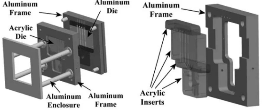
The die for this part is illustrated in Figure 7 and consisted in two halfs, one made of acrylic and the other of aluminum. The acrylic half was inserted in an aluminum frame and secured to the mobile platen of a Bühler SC/N53 industrial press at the Aluminium Technology Centre. The aluminum half was also inserted in an aluminum frame but was secured to the immobile platen of the press. An enclosure consisting of four horizontal arms was fixed on the aluminum frame of the acrylic section of the die to apply a pressure between the two sections and an O-ring was also placed between them. The high speed camera (Photron Fastcam PCI-10X) used to film the filling was also placed inside this enclosure. Filling typically lasted less than 0.5 s and was captured at
250 and 1000 frames/s with a shutter speed up to 1/2000 s. High intensity lighting with low current variation amplitude was also provided to the set-up.
Figure 7 – Diagram of the die and its components. The illustration on the right is an exploded view of the acrylic die and its aluminum frame
The tests were all carried out in a similar manner. Approximately 750 mL of fluid was placed in the shot sleeve and injected in the die by the piston which had been programmed to a fixed stroke length. During an injection, the piston velocity remained constant but two velocities (0.05 m/s and 0.3 m/s) were investigated. With water, these provided turbulent conditions with Reynolds numbers in the narrow section of the tensile bars of ~104 and ~5·104 and with tomato paste, the conditions were laminar with Reynolds numbers of ~10and ~100. A food coloring was mixed to the water to provide a greater contrast with the acrylic.
RESULTS AND DISCUSSION
Figure 8 provides four photographs of water filling the narrow and expanding sections of the tensile bars at a Reynolds number of ~104. Retouches were made to the pictures to improve their contrast. Even though the flow was turbulent, the fill fronts, outlined with white segments between the walls of the tensile bars, progressed as uniform planes. In HPDC, this is highly desirable to reduce air entrapment during filling [2]. The presence of large bubbles depicted in the Figure by the encircled regions was also observed. They rose faster than the fill fronts and formed continuously as though air was being pushed in the die. It was observed that this air originated from the shot sleeve and was injected by the piston along with the water. In HPDC, air entrained during injection has been reported to be a source of porosity in aluminum castings [14]. The results of the present physical modeling work indicate that the amount of entrained air can be significant.
Figure 8 – Water injection at a Reynolds number of ~104 in the narrow bar section. The fill fronts in the bars are outlined with white segments between the die walls. Large air
bubbles that formed are encircled. Filling was from bottom to top
Increasing the Reynolds number to ~5·104 had significant effects on the filling and close-up views were taken to provide greater details. In Figure 9, the lower section elbow of bar No. 1 (identified in Figure 6) is shown. In Figure 9A, the fill front appears with a large region of air entrapment. In Figures 9B, C and D, the fill front has passed the angle of view of the camera and regions of air entrapment are also present. These regions contained mostly water but had large amounts of air in them. The large bubbles observed at the lower Reynolds number (Figure 8) which originated from the air in the shot sleeve were replaced by a multitude of smaller ones.
Figure 9 - Close-up views of water injection in the exterior runner elbow of bar No. 1 and at a Reynolds number of ~5·104 in the narrow bar section. The white contour lines delimit regions that contained mostly water but had large amounts of air in them. The
outside of these regions contained water but much less air in them
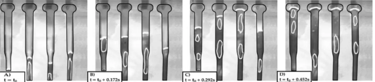
Close-up views of the expanding section of tensile bar No. 1 (identified in Figure 6) are also shown in Figure 10. The filling front, outlined with the white demarcations, appeared non-planar with signs of splashing. In HPDC, this filling condition is undesirable since it contributes to a greater porosity [2]. In Figure 10A, it is seen that the fluid jetted out of the narrow bar section without entirely filling the expanding section and droplets ahead of the filling front were also formed. In Figure 10D, the fill front has passed the angle of view of the camera and variations in the gray tones denotes air entrainment.
Figure 10 - Close-up views of water injection in the expanding section of a tensile bar at a Reynolds number of ~5·104. Filling fronts are delimited with white contour lines
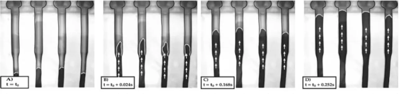
Very different flows were obtained when water was replaced by tomato paste. The tests with this fluid were carried out at the same injection velocities but the Reynolds numbers were lower and provided laminar regimes rather than turbulent ones. As shown in Figure 11, with a Reynolds number of ~10, the filling fronts were planar, well defined and stable. The presence of air originating from the shot sleeve reported earlier in the tests with water was not observed. The tomato paste was sufficiently viscous to form freestanding mounts that completely filled the opening of the runner/shot sleeve junction and this considerably reduced the amount of air injected by the piston. In Figure 11B, it is seen that as the fluid entered the expanding section of the tests bars, it did not immediately fully expand against the die walls. Instead it formed a small vertical column that expanded approximately twice the diameter of the reduced section after which it collapsed against the walls (Fig. 11B and C) and resumed its upward movement to the top of the die. The maximum height of the column seen in Figure 11B was dictated by factors such as inertia, viscosity, yield stress and surface tension.
Figure 11 – Tomato paste injection at a Reynolds number of ~10 in the narrow section of the bars
Differences in the flow fronts were observed when the injections were carried out at a Reynolds number of ~100. Figure 12 depicts close-ups ofthe lower section elbow of bar No. 1. There is a small increase in diameter located at the junction of the runner and the test bar that promoted the formation of air pockets depicted in Figures 12C and 12D. This entrapment was not observed with the tests at Re ~10.
Figure 12 – Close-up views of tomato paste injection in the exterior runner elbow in bar No. 1 and at a Reynolds number of ~100 in the narrow bar section
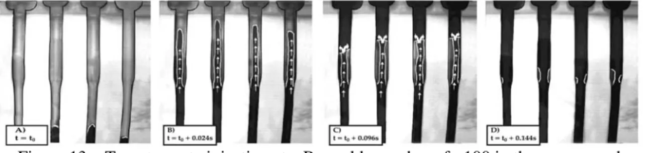
The filling fronts in the tensile bars are illustrated in Figure 13. They remained planar except in the expanding sections. The filling front was planar in the lower grip section (Fig. 13A) but became non-planar in the upper grip section (Fig. 13B). The flow then collided with the end of the cavity and filled the die from top to bottom by diverging to the sides (Figs. 13C and 13D). This backward filling front thus produced air entrapment and predicted that defects could occur in this region if tensile bars were produced from semi-solid aluminum under similar conditions. This was later confirmed by metallographic examinations of die cast A356 aluminum tensile bars [12,15]
Figure 13 – Tomato paste injection at a Reynolds number of ~100 in the narrow and expanding sections of the bars
CONCLUSION
The test carried out using water as an analogue for liquid aluminum to fill a die consisting of four tensile bars showed that planar filling fronts could be retained in the presence of turbulent regimes where the Reynolds number was ~104. The loss of planar filling fronts with accompanying air entrapments were observed when the Reynolds number was increased to ~5·104. A significant amount of air was also observed to be injected in the die by the piston at both Reynolds numbers. The tests carried out with tomato paste as an analogue fluid for the semi-solid aluminum showed that planar filling fronts were present at a Reynolds number of ~10. The loss of these planar filling fronts
was observed in the expanding section of the test bars when the Reynolds number was increased to ~100. Compared to water, injection of air by the piston was considerably reduced when tomato paste was used.
ACKNOWLEDGMENTS
Financial contributions from the Aluminium Technology Centre (ATC) of the National Research Council of Canada and the Chaire industrielle sur la solidification et la métallurgie de l’aluminium (CISMA) of Université du Québec à Chicoutimi (UQAC) are acknowledged. Technical assistance from Chang-Qing Zheng, at ATC is also acknowledged.
NOMENCLATURE
K Parameter in power law model ((Kg /m)s2-n)
L Pressure drop distance (m)
n Parameter in power law model
r Radial direction (m)
R Radius (m)
vz z-directed component of velocity (m/s)
P
Δ Pressure drop over length L (Pa) γ& Shear rate (s-1)
η Non-Newtonian viscosity (Pa⋅ ) s
μ Viscosity (Pa⋅ ) s
rz
τ Shear stress in the r direction due to flow in z direction (Pa) REFERENCES
1. J. L. Jorstad, “Semi-Solid Metal Processing; The High Integrity Die Casting Process”, Die Casting Engineer, Vol. 48, No. 1, 2004, 42-48.
2. E. J. Vinarcik, High Integrity Die Casting Processes, John Wiley & Sons, Inc., New York, NY, USA, 2003.
3. T. Iida and R.I.L. Guthrie, The Physical Properties of Liquid Metals, Oxford University Press, Toronto, ON, Canada, (1988).
4. M.C. Flemings, “Behavior of Metals Alloys in the Semisolid State”, Met. Trans., Vol. 22A, 1991, 957-981.
5. S.W. Hao, B.H. Hu, X.P. Niu, and R.D. Pehlke, “Atomization in High Pressure Die Casting – A problem and a Challenge”, Die Casting Engineer, Vol. 42, No. 5, 1998, 42-56.
6. W. Thorpe, V. Ahuja, M. Jahedi, P. Cleary, J. Ha, And N. Stokes, “Simulation of Fluid Flow Within the Die Cavity in High Pressure Die Casting Using Smooth Particle Hydrodynamics”, 20th International Die Casting Congress, Cleveland, Ohio, USA, 1999, 23-35.
7. J. Koke, M. Modigell, M. Hufschmidt and A. Alexandrou, “A Study on the Die Filling Behavior With Solid Fluids”, 6th International Conference on Semi-Solid Processing of Alloys and Composites, Edimet, Turin, Italy 2000, 635-639. 8. T.G. NGuyen, D. Favier and M. Suery, “ Theoretical and Experimental Study of the
Isothermal Mechanical Behavior of Alloys in the Semi-Solid State”, International Journal of Plasticity, Vol. 10, 1994, 663-693.
9. L. Orgéas, J.-P. Gabathuler, C.J. Paradies, T. Imwinkelried and M. Rappaz, “Modelling of Semi-Solid Processing Using a Modified Temperature-Dependent Power-Law Model”, Modelling and Simulations in Materials Science and Engineering, Vol. 11, 2003, 553-574.
10. B.S. Massey, Mechanics of Fluids, sixth edition, Van Nostrand Reinhold (International) Co. Ltd., London, Great Britain, 1989.
11. Q.Y. Pan and D. Apelian, “Yield Stress of Aluminum Alloys in the Semi-Solid State”, 6th International Conference on Semi-Solid Processing of Alloys and Composites, Edimet, Turin, Italy 2000, 399-404.
12. M. Forté, “Modélisation de l’écoulement de l’aluminium semi-solide dans le moulage sous pression”, Master’s thesis, Université du Québec à Chicoutimi, Chicoutimi, Québec, Canada, 2006.
13. R. B. Bird, W. E. Stewart and E. N. Lightfoot, Transport Phenomena, 2nd Ed., John Wiley & Sons, Inc., New York, NY, USA, 2002.
14. L. Winkler, “Reducing Gas Porosity in High Pressure Die Casting”, NADCA, Transactions of the die casting sessions, CastExpo’05, St-Louis, Missouri, U.S.A 2005, Paper T05-023 – CD ROM.
15. M. Forté, D. Bouchard, and A. Charette, “Fluid Flow Investigation of Die Cast Tensile Test Bars”, submitted to: 9th S2P Conference, Sept. 11-13 2006, Busan, Korea.