Publisher’s version / Version de l'éditeur:
Vous avez des questions? Nous pouvons vous aider. Pour communiquer directement avec un auteur, consultez la première page de la revue dans laquelle son article a été publié afin de trouver ses coordonnées. Si vous n’arrivez pas à les repérer, communiquez avec nous à [email protected].
Questions? Contact the NRC Publications Archive team at
[email protected]. If you wish to email the authors directly, please see the first page of the publication for their contact information.
https://publications-cnrc.canada.ca/fra/droits
L’accès à ce site Web et l’utilisation de son contenu sont assujettis aux conditions présentées dans le site LISEZ CES CONDITIONS ATTENTIVEMENT AVANT D’UTILISER CE SITE WEB.
Fire Study (National Research Council of Canada. Division of Building Research),
1973-02
READ THESE TERMS AND CONDITIONS CAREFULLY BEFORE USING THIS WEBSITE. https://nrc-publications.canada.ca/eng/copyright
NRC Publications Archive Record / Notice des Archives des publications du CNRC :
https://nrc-publications.canada.ca/eng/view/object/?id=69476676-69aa-46a5-943c-bc318055f10e https://publications-cnrc.canada.ca/fra/voir/objet/?id=69476676-69aa-46a5-943c-bc318055f10e
NRC Publications Archive
Archives des publications du CNRC
For the publisher’s version, please access the DOI link below./ Pour consulter la version de l’éditeur, utilisez le lien DOI ci-dessous.
https://doi.org/10.4224/40001359
Access and use of this website and the material on it are subject to the Terms and Conditions set forth at
Fire tests on protected steel columns with different cross-sections
Stanzak, W. W.; Lie, T. T.
NATIONAL RESEARCH COUNCIL O F CANADA DIVISION O F BUILDING RESEARCH
F I R E TESTS ON P R O T E C T E D S T E E L COLUMNS WITH D I F F E R E N T (;ROSS -SECTIONS
by W. W. STANZAK and T. T. L I E F i r e Study No. 30 of the Division of Building R e s e a r c h OTTAWA F e b r u a r y 1973
FIRE TESTS ON PROTECTED STEEL COLUMNS WITH DIFFERENT CROSS -SECTIONS
by
W. W. STANZAK* and T. T. LIE**
SUMMARY
Seven f i r e t e s t s were conducted to provide experimental data showing how column f i r e endurance varies with the size and shape of the s t e e l cross-section. All columns were protected with the s a m e thickness of insulating material. The results a r e plotted to show how generalized f i r e endurance ratings can be developed f o r a particular protective material.
*,
**
Steel Industries Fellow and Research Officer, respectively, F i r e Research Section, Division of Building Research, National Research Council of Canada.FIRE TESTS ON PROTECTED S T E E L COLUMNS WITH DIFFERENT CROSS -SECTIONS
by
W. W. STANZAK and T. T. LIE
Seven f i r e t e s t s on identically protected s t e e l columns w e r e conducted a s p a r t of an extensive column r e s e a r c h program at the Division of Building Research. The specimens w e r e designed t o i l l u s t r a t e how column f i r e resistance v a r i e s with the s i z e and shape (geometry) of the s t e e l cross-section. As the methods and m a t e r i a l s employed in the construction of the t e s t specimens a r e currently used in Canada, the r e s u l t s of this study a r e directly applicable in design.
PROTECTION
All specimens w e r e protected by one-inch thick vermiculite boards cemented together and t o the s t e e l with an adhesive m o r t a r . Vicuclad boards a r e produced from specially selected vermiculite which, after pre-treatment, i s bonded with an inorganic binder to
produce a non-combustible board. William ~ e n ~ b n and Sons (Vicuclad) Ltd.
,
Cheshire, England, have provided the following technical data concerning their product:T h e r m a l conductivity: k = 0. 53 Btu in. /ft% deg F at 100 deg
F
meanStandard size: 2 ft by 2 ft and 3 ft by 2 ft
Standard thickness:
Nominal density:
(inches) 3/4, 1, 1 1/4, 1 1/2, i, and 2 1/8
Weight
p e r
s q ft: Vicuclad contains: V e r m i c u l i t e contains: 1 i n a t h i c k 2 1/4 lb; 1 1 / ~ in. t h i c k 3 1 / ~ lb; 2 1/8 in. t h i c k 4 3 / 4 lb; 1 1 / 4 in. t h i c k 3 lb; 2 in. t h i c k 4 1/2 1b 65 p e r c e n t V e r m i c u l i t e (* 5 p e r cent) 35 p e r cent Sodium S i l i c a t e(f
5 p e r cent)40 p e r cent S i l i c a 1 L p e r cent Alumina
5 p e r c e n t F e r r i c Oxide 17 p e r c e n t Magnesium Oxide
11 p e r c e n t F r e e and Combined W a t e r T h e Sodium S i l i c a t e h a s a SiO; Na,O r a t i o of 3. 3:l
T h e a d h e s i v e when d r y i s a 10:7 m i x t u r e of Sodium S i l i c a t e and V e r m i c u l i t e . T h e d e n s i t y of Vicuclad is 27 l b
(f
1 5 p e r cent) lb p e r cubic foot.T h e c o m p r e s s i v e s t r e n g t h of Vicuclad i s 135 l b
(f
15 p e r c e n t ) l b p e r s q u a r e inch.DESCRIPTION O F TEST SPECLMENS
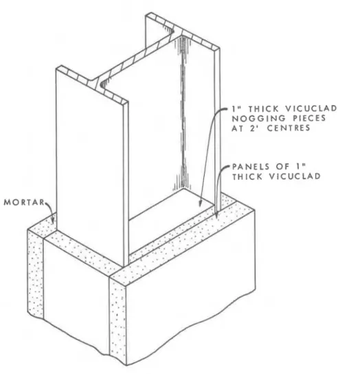
T h e s t e e l c r o s s - s e c t i o n s u n d e r t e s t a r e specified i n T a b l e I. T h e y w e r e supplied with welded end p l a t e s and i n s u l a t e d , a s required('). Insulating m a t e r i a l w a s applied i n t h e f o r m of box e n c a s e m e n t on a l l t y p e s of s e c t i o n (hollow, wide flange and solid).
T h e wide flange c o l u m n s w e r e fitted with nogging p i e c e s of 1-in.
t h i c k Vicuclad, fixed between t h e f l a n g e s and t o t h e web with a d h e s i v e m o r t a r . T h e noggings w e r e s p a c e d a t 2-ft c e n t r e s on e a c h s i d e of t h e column. T h e Vicuclad p a n e l s w e r e fixed t o t h e o u t e r f a c e s of t h e f l a n g e s with t h e s a m e a d h e s i v e m o r t a r . T o c o m p l e t e t h e e n c a s e m e n t , additional p a n e l s w e r e fixed t o t h e noggings and t o t h e Vicuclad p a n e l s a l r e a d y in place. T h e d e t a i l s of t h e column e n c a s e m e n t a r e shown in F i g u r e s 1, 2 and 3.
T E S T PROCEDURE
T h e t e s t s w e r e c a r r i e d out i n a c c o r d a n c e with CSA B54. 3-64(11. T h e c o l u m n w a s t e s t e d v e r t i c a l l y in a g a s - f i r e d f u r n a c e . T h e f u r n a c e
t e m p e r a t u r e w a s m e a s u r e d by nine t h e r m o c o u p l e s positioned s y r n m e t r i c a l l y about t h e c o l u m n a s shown i n F i g u r e 4.
T h e t h e r m o c o u p l e s w e r e enclosed in 1 / ~ - i n . b l a c k i r o n pipe with a c a r b o n s t e e l c a p a t t h e tip. T h e hot junction of the t h e r m o c o u p l e s was p l a c e d
t e m p e r a t u r e s at the nine points and the average of the nine thermocouples w e r e recorded during the t e s t .
The fuel input t o the furnace was controlled to make the average t e m p e r a t u r e follow a s closely a s possible the t e m p e r a t u r e v e r s u s t i m e
c u r v e p r e s c r i b e d by
CSA
B54. 3-64.The t e m p e r a t u r e of the s t e e l columns was m e a s u r e d by t h e r m o - couples peened into the steel at five levels. The location of t h e s e t h e r m o - couples i s shown in F i g u r e s 5 and 6.
OBSERVATIONS
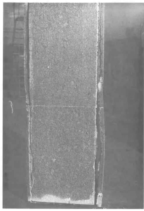
The cladding remained intact throughout the t e s t s without exception. Towards the end of the longer t e s t s ( 3 to 4 h r s ) c r a c k s developed in the
v e r t i c a l joints of the Vicuclad panels. The s t r u c t u r a l strength of the encasement was noticeably affected by the t e s t and in s e v e r a l instances pieces of the Vicuclad panels I'ell away from the column a s it was being removed f r o m the furnace.
F i g u r e s 7 and 8 show a column before and after the f i r e t e s t . The deterioration at t h e joints, evident in F i g u r e
9,
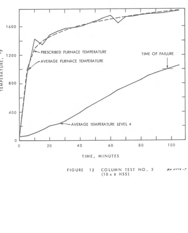
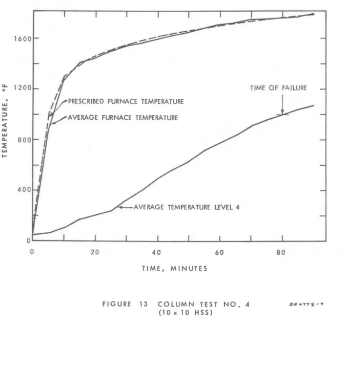
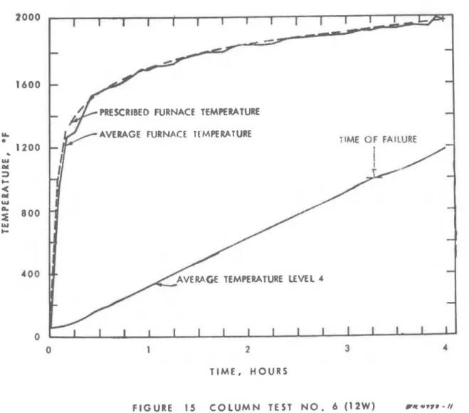
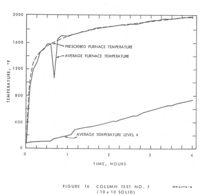
i s typical of the longer t e s t s . RESULTSF i r e endurance t i m e s derived by the t e s t s a r e shown in Table I. T h e furnace t e m p e r a t u r e and the t e m p e r a t u r e of the l e v e l at which f a i l u r e o c c u r r e d a r e plotted against t i m e in F i g u r e s 1 0 t o 16.
It
was d e s i r a b l e to generalize t h i s f i r e t e s t data t o develop what might be called "universal f i r e r e s i s t a n c e ratings" for columns of any geometry with protective m a t e r i a l of various thicknesses. This i s now possible by utilizing knowledge a l r e a d y gained f r o m the DBR/NRC columnr e s e a r c h p r o g r a m .
The authors found that f o r relatively s t a b l e low density m a t e r i a l s the f i r e endurance t i m e of any rotected s t e e l column can be calculated by
R,
the s e m i - e m p i r i c a l expression
.
where: T = calculated f i r e endurance time, h r C
W = weight of s t e e l section p e r unit length, lb/ft
D = heated p e r i m e t e r , in. (development of inside s u r f a c e of protective m a t e r i a l )
A
=
thickness of protection, in.T h e 0. 5 t e r m r e p r e s e n t s a c o n s t a n t t h a t w a s found t o be a good a v e r a g e f o r popular ( c h e m i c a l l y s t a b l e ) f i r e p r o t e c t i v e m a t e r i a l s and t h e t e r m W / D r e f l e c t s t h e g e o m e t r y of t h e p r o t e c t e d column and i s c a l l e d t h e " s i z e and
shape" f a c t o r . F i r e t e s t d a t a developed i n t h i s t e s t s e r i e s and one unpublished t e s t point f r o m another l a b o r a t o r y f o r a m a t e r i a l t h i c k n e s s of 1 1/2 i c . a r e shown in F i g u r e 17 and a r e c o m p a r e d with t h e f i r e r e s i s t a n c e s c a l c u l a t e d by Equation 1 (a). As i s s e e n , t h e calculated f i r e r e s i s t a n c e t i m e s a r e q u i t e c o n s e r v a t i v e .
A s s i x s e t s of f i r e t e s t d a t a a r e on hand h e r e , it i s p o s s i b l e t o develop
a b e t t e r f o r m of Equation 1 ( a ) by s u m m i n g t h e f i r e r e s i s t a n c e t i m e s and solving f o r a m o r e a p p r o p r i a t e value of t h e constant:
W
T = (LO
-
+
0. 68)R
C D Pw h e r e t h e t e r m s h a v e t h e s a m e m e a n i n g a s before. F i g u r e 18 again shows t h e a v a i l a b l e f i r e t e s t d a t a a s well a s t h e f i r e r e s i s t a n c e s c a l c u i a t e d by Equation 1 (b), T h e a g r e e m e n t between t e s t d a t a and c a l c u l a t e d r e s u l t s
is good, and t h e c a l c u l a t e d v a l u e s a r e m o s t l y c o n s e r v a t i v e . Accordingly, Equation 1 (b) and t h e c o r r e s p o n d i n g l i n e s in F i g u r e 18, m a y b e talcen a s
" u n i v e r s a l f i r e r e s i s t a n c e r a t i n g s " f o r t h i s p r o t e c t i v e m a t e r i a l . 'l:
ACKNOWLEDGEMENT
T h i s w o r k w a s c a r r i e d out u n d e r a c o o p e r a t i v e p r o g r a m between DBR/NRC and t h e Canadian S t e e l I n d u s t r i e s C o n s t r u c t i o n Council, known a s t h e S t e e l I n d u s t r i e s F e l l o w s h i p A g r e e m e n t .
T h e a u t h o r s w i s h t o t h a n k M e s s r s . J. E. B e r n d t and E. 0. P o r t e o u s , who c a r r i e d out t h e f i r e t e s t s and a s s i s t e d i n a n a l y s i s of t h e d a t a developed. R E F E R E N C E
1. Methods of F i r e T e s t s of Walls, P a r t i t i o n s , F l o o r s , Roofs, C e i l i n g s , Columns, B e a m s and G i r d e r s . CSA S t a n d a r d B54. 3-1964, C a n a d i a n S t a n d a r d s A s s o c i a t i o n , Ottawa, Ontario, Canada.
2. Lie, T. T. and Stanzak, W. W. F i r e R e s i s t a n c e of P r o t e c t e d S t e e l Columns. ( In p r e p a r a t i o n )
>:< No f i r e r e s i s t a n c e exceeding 4 h r should be c a l c u l a t e d b y Equation 1 (b), a s t h i s w a s t h e m a x i m u m t i m e t h e m a t e r i a l w a s shown, by t e s t , t o r e m a i n r e l a t i v e l y i n t a c t .
TABLE I
F I R E RESISTANCE O F VARIOUS IDENTICALLY PROTECTED COLUMN SECTIONS
NO. Section W D W/D ~ ( m i n ) T (min) ~ ~ ( h r )
c E FRC 1 14W 136 59 2.30 143 153 2.55 2 2 10W 49 40 1.22 9 5 96 1. 60 1 1/2 3 l o x 6 HSS 36.8 32 1.15 9 2 9 8 1. 63 1 1/2 4 10x1 0 HSS 39.7 40 0.99 8 4 7 9 1. 32 1 5 12x12 HSS 57 48 1. 19 9 4 100 1. 67 1 1/2 6 12W 190 54 3.52 197 196 3. 27 3 7 lOxlOSOLID* 342 40 8.55 42 1
-
-
*
4+D = heated p e r i m e t e r (in.), i. e. development of i n s i d e s u r f a c e of p r o t e c t i v e m a t e r i a l
W = weight of s t e e l s e c t i o n p e r unit height, lb/ft T = f i r e endurance t i m e calculated b y equation 1 (b)
C
T = e x p e r i m e n t a l f i r e endurance t i m e derived by t e s t E
FRC = F i r e R e s i s t a n c e Classification, h r
*
T h e f i r e t e s t on t h i s s p e c i m e n was t e r m i n a t e d a t 4 h r . F a i l u r e had not taken p l a c e by t h a t t i m e .MOR
N E L S O F V I C U C L A D
M O R T A R
FIGURE 2
1'
->.--
TOTAL OF 9 THERMOCOUPLES R A L TC SIDE 0
C
3 / 4 " B L A C K IRON PlPE UNINSULATED 3 " B L A C K IRON COLUMNu
P l P E I N S U L A T E D FIGURE 4 L O C A T I O N OF FURNACE THERMOCOUPLES I N RELATION TO COLUMN I R 4 7 9 ~-
zL E V E L 2 L E V E L 3 . - . L E V E L 4 L E V E L 5 F I G U R E 5 D I S T A N C E F R O M THE B O T T O M L E V E L 1
-
6 ' L E V E L 2-
5'
L E V E L 3-
4 ' L E V E L 4-
3 ' L E V E L 5 - 2 ' T H E R M O C O U P L E L O C A T I O N O F T H E R M O C O U P L E S O N W I D E - F L A N G E C O L U M N S . ma? 477u - 3LEVEL LEVEL LEVEL LEVEL LEVEL F I G U R E 6 D I S T A N C E F R O M THE B O T T O M LEVEL 1
-
6 ' LEVEL 2-
5 ' LEVEL 3-
4'
LEVEL 4-
3 ' LEVEL 5-
2 ' T H E R M O C O U P L E L O C A T I O N O F T H E R M O C O U P L E S O N R E C T A N G U L A R C O L U M N S S R + 7 7 8 - Y.
-
----
ITIME, HOURS RESCRIBED FURNACE TEMPERATURE AVERAGE FURNACE TEMPERATURE
TIME OF FAILURE
AVERAGE TEMPERATURE LEVEL 4
PRESCRIBED FURNACE TEMPERATURE AVERAGE FURNACE TEMPERATURE
ERAGE TEMPERATURE LEVEL 4
TIME, MINUTES
i 1 - 1 i I I
IY
-
-
PRESCRIBED FURNACE TEMPERATURE TIME OF FAILURE
-
AVERAGE FURNACE TEMPERATURE
-
-
-
-
AVERAGE TEMPERATURE LEVEL 4
-
L 1 I I 1 I t I I I 1
T I M E , M I N U T E S
FIGURE 1 2 C O L U M N TEST N O . 3 pr Y 7 7 8 -7 ( 1 0 x 6 HSS)
f 1 2 0 0 L
8
TIME OF FAILURETIME, MINUTES
FIGURE 13 COLUMN T E S T N O . 4 ( l o x 10 HSS)
-
-
-
PRESCRIBED FURNACE TEMPERATURE
TIME OF FAILURE
-
-
-
I
-
-
AVERAGE TEMPERATURE LEVEL 3
-
T I M E , M I N U T E S
F I G U R E 1 4 C O L U M N TEST N O . 5
-
-
-
AVERAGE FURNACE Tf MPERATURE TIME OF FAlLURE
-
-
1 2 3
TIME, HOURS
1 I I 1 1 I I I I I I I I
-
-
PRESCRIBED FURNACE TEMPERATURE
HAVERAGE FURNACE TEMPERATURE -
-
-
-
-
AVERAGE TEMPERATURE LEVEL 4
-
1 1 1 1 1 I 1 I I I 1 I 1 I I I
1 2
T I M E , HOURS
FIGURE 16 C O L U M N TEST N O ( l o x 10 S O L I D )
Ib/ft
"
S I Z E A N D SHAPE"
F A C T O R W/D-
in. F I G U R E 17 G E N E R A L I Z E D P L O T O F C O L U M N FIRE R E S I S T A N C E,
f = 2 7 1b/ft3 B I S O 8 L-
LIb/ft " S I Z E A N D S H A P E " F A C T O R W/D,