HAL Id: hal-02107662
https://hal.archives-ouvertes.fr/hal-02107662
Submitted on 23 Apr 2019
HAL is a multi-disciplinary open access
archive for the deposit and dissemination of
sci-entific research documents, whether they are
pub-lished or not. The documents may come from
teaching and research institutions in France or
abroad, or from public or private research centers.
L’archive ouverte pluridisciplinaire HAL, est
destinée au dépôt et à la diffusion de documents
scientifiques de niveau recherche, publiés ou non,
émanant des établissements d’enseignement et de
recherche français ou étrangers, des laboratoires
publics ou privés.
Phase sensitive amplification enabled by coherent
population trapping
P. Neveu, C Banerjee, J. Lugani, F. Bretenaker, E. Brion, F. Goldfarb
To cite this version:
P. Neveu, C Banerjee, J. Lugani, F. Bretenaker, E. Brion, et al.. Phase sensitive amplification enabled
by coherent population trapping. New Journal of Physics, Institute of Physics: Open Access Journals,
2018, 20 (8), pp.083043. �10.1088/1367-2630/aadb79�. �hal-02107662�
Light and Matter Physics Group, Raman Research Institute, Bangalore 560080, India
4 Author to whom any correspondence should be addressed.
E-mail:[email protected]
Keywords: four-wave mixing, coherent population trapping, two-mode squeezing, phase sensitive amplification
Abstract
We isolate a novel four-wave mixing process, enabled by coherent population trapping
(CPT), leading
to efficient phase sensitive amplification. This process is permitted by the exploitation of two
transitions starting from the same twofold degenerate ground state. One of the transitions is used for
CPT, defining bright and dark states from which ultra intense four-wave mixing is obtained via the
other transition. This leads to the measurement of a strong phase sensitive gain even for low optical
densities and out-of-resonance excitation. The enhancement of four-wave mixing is interpreted in the
framework of the dark-state polariton formalism.
1. Introduction
Optical parametric amplification processes have been widely studied for their unique noise properties and their many possible applications in metrology[1], imaging [2] and telecommunications [3]. They have thus been
implemented in different media such as nonlinear crystals and waveguides[4] through three-wave mixing (χ(2)
process) or fibers [5] through four-wave mixing (χ(3)process) (FWM): one or two strong driving pump field(s) play the role of a reservoir of photons for a signal and an idlerfields. Depending on the relative phase between thesefields, photons can be transferred from the pump(s) to the signal and idler fields or conversely. Such noiseless phase sensitive amplification (PSA) processes allow for the amplification of a coherent state of light into another minimum uncertainty state, keeping the product of thefield quadratures variances constant [6]. This is
associated with the generation of squeezed states of light, which are of interest for quantum optics, atomic memories, entanglement swapping, and quantum information processing protocols[7]. Very large quantum
noise reductions up to 15 dB have been achieved using crystals[8], but down-converted photons are spectrally
mismatched with atomic systems used for quantum memories and PSA achieved directly through FWM in atomic systems like alkali vapors is a subject of active interest[9–11].
In atomic systems, FWM efficiency can be boosted up using coherent population trapping (CPT) [12]. This
two-photon process arises in aΛ-system and suppresses the absorption of a light field even at optical resonance by optically pumping the population into a dark state, which is a coherent superposition of two states.
Consequently, this linear absorption suppression makes multiphoton processes such asχ(3)processes predominant. Theoretical proposals based on CPT enhancement of FWM were put forward in double-Λ systems[13] and experimental implementations were also reported in rubidium [14,15], sodium [16], and
cesium[17].
However, because of their hyperfine structure, alkali atoms do not offer convenient closed Λ-systems. In this paper, following the experimental results of[18], we exploit the simple level structure of metastable helium 4:
because of selection rules, the D1transition constitutes a well defined closed lambda system, allowing for a strong
CPT effect to occur. Two other transitions share the same ground states, which can then be fully exploited to have multiphoton nonlinear processes explicitly addressing the dark and bright states. Therefore, we expect this atom to exhibit a strong nonlinear third-order susceptibility while being free from absorption. We moreover 20 August 2018
PUBLISHED
30 August 2018
Original content from this work may be used under the terms of theCreative Commons Attribution 3.0 licence.
Any further distribution of this work must maintain attribution to the author(s) and the title of the work, journal citation and DOI.
develop an analytic treatment to extract the properties of the amplification process, and show that it has the properties of a perfect squeezer[19].
2. Experiment and modeling
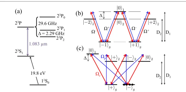
The relevant level structure of helium is shown infigure1(a): the long lived23S
1metastable state is populated using a radio-frequency discharge, and optically coupled to the23Pfine states at wavelengths close to 1.083 μm.
The upper level P3
0is separated from the3P1states by more than 20 times the Doppler broadening
W;2π×0.9 GHz and can thus be overlooked. The decay rate Γ of the optical coherence at room temperature in the 1 Torr helium cell is about 2π×23 MHz, but following [20,21], its value is replaced by the Doppler width
W in the simulations performed below.
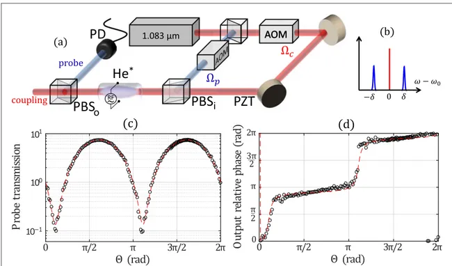
The experimental set-up is schemed infigure2(a). The S23 2P
1« 3 1(D1) helium transition is resonantly
excited by a strong 200 W cm−2couplingfield and a weak 0.50 W cm−2probefield, of respective Rabi
frequenciesΩcandΩp, with∣Wp∣∣Wc∣. The coupling and probefields are orthogonally and linearly polarized so that the Rabi frequencies involved in the circularly polarized light basisσ±are:
1
2 c i p . 1
W = (W W ) ( )
In PSA configuration, the probe field contains two frequencies, separated by ±δ from the coupling field frequency(see figure2(b)), and called signal and idler. A typical probe transmission experimental measurement
in PSA configuration is reproduced in figure2(c): a maximum gain equal to 9.3 dB is observed for the probe field.
As the transition23S m 0 2P m 0
1( = )« 3 1( = )is forbidden, the resonant interaction with thefields leads to aΛ-type level scheme for the D1transition(see figure1(b)), where the3S1,3P1and P3 2states are labeled by the indices g, 1 and 2, respectively. Because the linearly polarized excitation of thisΛ-system leads to a strong CPT effect, which suppresses the D1transition linear absorption, one needs to take into account the nearest transition
tofind the most efficient multiphoton processes [12]. The Zeeman sublevels involved in the different processes
are labeled by their m magnetic quantum numbers:∣ ñ =1g ∣23S m1, = ñ1 and∣0ñ =1 ∣23P m1, = ñ0 are the relevant ground and excited states of the D1transition, while∣ ñ =22 ∣23P m2, = ñ2 and
P m
0ñ =2 23 2, = ñ0
∣ ∣ are coupled to the ground states∣ ñ1gby the D2transition. The population of the
S m
23 , 0
1 = ñ
∣ state through the far-detuned23S 2P
1« 3 2(D2) transition can be neglected (Δ/2π=2.29 GHz),
and therefore the 23P m, 1
2 = ñ
∣ states are also not relevant. In the rotating wave approximation, the interaction Hamiltonian H in the atomic basis =at {∣0 ,ñ1 ∣- ñ1 ,g ∣+ ñ1 , 0 ,g ∣ ñ2 ∣- ñ2 ,2 ∣+ ñ22}, is given by:
Figure 1.(a) Level scheme in helium 4. The D1transition( S231«23P1) is resonantly excited, while the D2transition( S23 1«23P2) is
far detuned byΔ (the P3
0level is far away and can be overlooked): excitation schemes are shown in the atomic basisat(b) and in the
dark and bright states basissdefined by the coupling field (c). The S31, P31and P32states are labeled by the indices g, 1 and 2,
respectively. Due to selections rules and optical pumping, gray-shadowed Zeeman levels can be neglected and the relevant ones are labeled using their m numbers. CPT occurs through the D1transition, pumping the population into the∣-ñgstate, thus inducing full
transparency and enabling for efficient multiphoton processes.
2
0 0 0 0 0 0 3 2 0 0 0 3 0 2 0 3 3 0 0 0 2 0 0 0 0 0 2 0 0 , 2 * * * * * * W W W -W W W W - W -W W D W D - W D + -+ + -- - + + -+ ⎛ ⎝ ⎜ ⎜ ⎜ ⎜ ⎜ ⎜ ⎜ ⎜ ⎜ ⎜ ⎜ ⎞ ⎠ ⎟ ⎟ ⎟ ⎟ ⎟ ⎟ ⎟ ⎟ ⎟ ⎟ ⎟ ( )
where the numerical factors originate from the Clebsch–Gordan coefficients.
One can then derive the evolution of the density matrixρ via optical Bloch equations:
H
i¶ =tr [ ,r]+( )r , ( )3
wherestands for the non Hermitian dynamics caused by spontaneous emission and extra optical coherence decay, of ratesΓ0andΓ, respectively. The fields along z then propagate according to Maxwell’s equations in the
slowly varying envelope approximation:
c ic 1 3 2 , 4 z t h r02 1g r 22 1g r01 1g ¶ + ¶ W = - - ⎛ ⎝ ⎜ ⎞ ⎠ ⎟ ( ) ( )
whereη is the atom-field coupling coefficient,rij=Tr[ ∣riñáj∣], and numerical factors are given by Clebsch–
Gordan coefficients.
3. Results
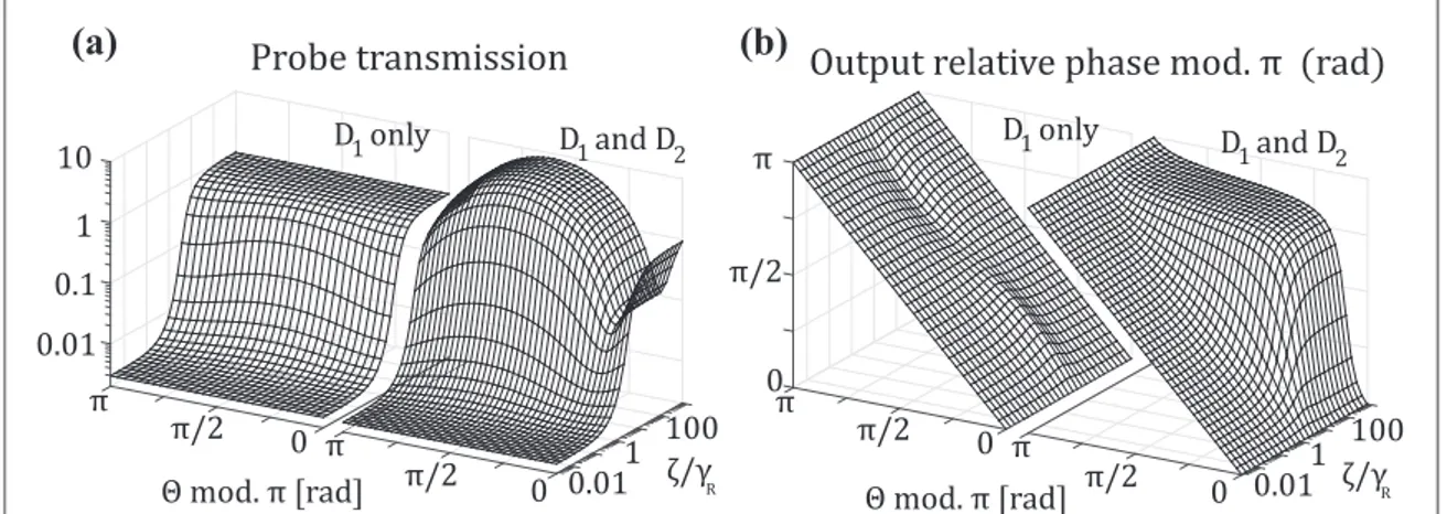
Figure3(a) shows the result of the numerical simulations of the probe field intensity transmission coefficient in
the degenerate case(δ=0), as a function of its relative phase Θ with respect to the coupling field and the power-broadening factorz = W G of the couplingc2 field normalized to the Raman coherence decay rate γRbetween
Figure 2.(a) Experimental setup. A laser diode at 1.083 μm is used to generate orthogonally and linearly polarized probe and coupling fields ΩpandΩc, the latter one being amplified by a tapered amplifier. Acousto-optic modulators (AOM) enable to generate arbitrary spectra for thefields, such as the typical degenerate pump PSA scheme represented in (b). Two electrodes placed apart the cell generate a breakdown voltage at 27 MHz radio-frequency(RF): collisions with the electrons of the plasma then pump the atoms to the metastable state23S
1. The input relative phaseΘ between signal (w0+d), idler (w0-d), and coupling (w ) fields is tuned using a0
piezoelectric transducer(PZT). The sideband signal and idler fields transmission through the 6 cm long cell is measured by a photodiode(PD). Input (output) relative phase between probe and coupling fields is measured via a small leakage of the fields at the cell input beamsplitter PBSi(the coupling field at the cell output beamsplitterPBSo). (c) When the relative phase is scanned with
2 2 kHz
d= p´ , one observes a PSA of the sidebandsfields with a maximum gain equal to 7.4 (8.7 dB) and (d) the associated stabilization of the probefield relative phase with the coupling field. Gains up to 9.3 dB have been measured. Open circles: measurements. Dashed lines:fit with μ=1.18 using equation (7).
the levels∣ ñ1g. For clarity, we compare a numerical simulation where the D1transition is considered alone
(right panel) with another where the D1and the D2transitions are both considered(left panel). In both cases,
CPT occurs when the couplingfield strength overcomes the Raman coherence decay rate γR. Below this
threshold(i.e., for ζ/γR=1), the resonant absorption by the D1transition forbids any multiphoton process.
Above this threshold,(i.e., for ζ/γR?1), CPT becomes efficient: PSA then occurs with a gain as large as 8.5 for
an optical depth of 4.5 only when the D2line is taken into account while, whatever the phase is, the probe
transmission remains 1 for large values ofζ when the D2transition is overlooked. Moreover,figure3(b) shows
the evolution of the output relative phase in the same conditions. In the regime where CPT does not exist (ζ/γR=1), the phase is unchanged through propagation. However, when CPT exists (ζ/γR?1) the output
relative phase is stabilized to the specific value ΘMAX, as experimentally observed infigure2(d). These
simulations are computed with decay rates parameters which correspond to experimental measurements. Let us now focus on the degenerate caseδ=0 and assume ζ?γR. In the steady state regime, restricting
equation(4) for ΩcandΩpto the leading order terms inΩp/Ωcleads to:
4i 3 , , 5 z c c h z ¶ W = DW + G D ⎜ ⎟ ⎛ ⎝ ⎞ ⎠ ( ) 4i 3 2 , , 6 z p p c c p c * * * h z ¶ W = D W W - W W W + G D ⎜ ⎟ ⎛ ⎝ ⎞ ⎠ ( )
where the terms(G,z D)contain multiphoton processes involving several times the D2far-detuned
transition.
Equation(5) yieldsWc( )L = Wc( )0 exp i( )m wherem = 34 L h
D and L is the length of the atomic medium: the couplingfield experiences a phase shift along its propagation because of the far-detuned D2transition. Here, the
couplingfield depletion by the probe field is neglected due to the first order approximation in Ωp/Ωc. This
expression can then be used to solve equation(6), leading to:
L L 1 i e i e i e 1 i e 0 0 , 7 p p p p i i i i * * m m m m W W = + - -W W m m m m - -⎛ ⎝ ⎜⎜ ⎞⎠⎟⎟ ⎛⎝⎜ ⎞ ⎠ ⎟⎛ ⎝ ⎜⎜ ⎞⎠⎟⎟ ( ) ( ) ( ) ( ) ( ) ( ) ( )
where one recognizes a typical PSA transfer matrix belonging to the symplectic group[19]. It provides a gain
G( )Q º W∣ p(L,Q W) p( )∣0 2of maximum and minimum values GMAXand GMIN:
GMAX= +1 2m m( + 1+m2)=1 GMIN, ( )8 where the valuesΘMAXandΘMINof the initial relative phaseΘ between the fields are given by:
1 2arctan 1 2 . 9 MAX MIN m p p Q = ⎛ = + Q ⎝ ⎜ ⎞ ⎠ ⎟ [ ] ( )
At the quantum level, the properties of such a non-unitary transfer matrix ensure that no extra noise is added during the amplification process, leading to squeezed state generation.
Figure 3.(a) Simulated transmission of the probe field based on the Maxwell–Bloch formalism when the fields are degenerate (δ=0), not taking(right) and taking (left) into account the D2transition. All the parameters such as optical depth and decay rates corresponds to the ones measured experimentally. The probe transmission is plotted as a function of its initial relative phaseΘ with the coupling field and of the coupling field strength normalized to the Raman coherence decay rate ζ/γR. When CPT is efficient (ζ/γR?1), the D1 transition becomes transparent and PSA occurs via the D2levels. The value of the optical depth of the medium used for this plot is extracted from experimental measurements.(b) Evolution of the output relative phase between the probe and the coupling field in the same conditions. When CPT is efficient (ζ/γR?1), PSA induces a stabilization of the output relative phase to the value ΘMAX.
4
The validity of our model to describe the experimental results is shown onfigures2(c) and (d). The broken
linesfit the experimental data with gain and output phase transfer functions that are derived from equation (7).
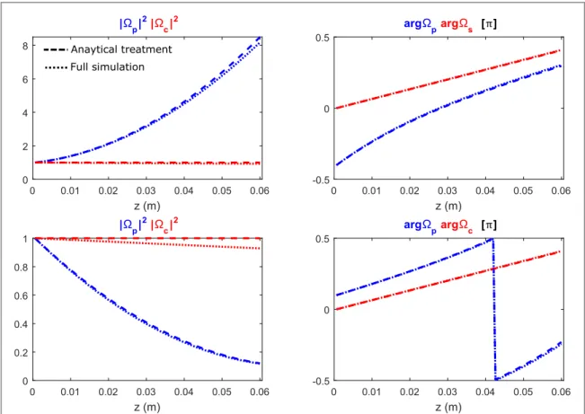
Finally, we investigate the validity of our approximation framework by comparing the analytical results with the full simulation of the Maxwell–Bloch formalism. Figure4displays the intensities and phases of the probe and couplingfields during propagation, for an initial relative phase ΘMAX(ΘMIN) corresponding to a maximal gain
GMAX(minimal gain GMIN). Despite an excellent agreement, a small discrepancy is noticeable in particular on
the couplingfield intensity. Indeed, some residual D2absorption occurs, which is not taken into account in the
analytical treatment.
Contrary to usual far off-resonance FWM schemes, the gain scales here as 1/Δ. Moreover, contrary to the usual PSA behavior, the maximum reachable gain GMAXdoes not explicitly depend on the couplingfield
intensity but only onμ, which is proportional to the optical depth of the medium. Indeed, as shown in figure3, this process is possible only when the atoms are pumped into the dark state, which occurs whenζ?γRand
does not result from any strong saturation effect.
4. Discussion
To understand the underlying mechanism, it is interesting to switch to the CPT dark(∣-ñg) and bright (∣+ñg) state basis defined by the coupling field, which assigns different transitions to the coupling and probe fields [22]:
1 1 2 . 10 g g g ñ = + ñ - ñ ∣ ∣ ∣ ( )
When the Zeeman sublevels are degenerate, the coupling(probe) field couples the∣+ñg(∣-ñg) state to the 0∣ ñe state. Optical pumping in the∣-ñgstate suppresses the linear absorption by the D1transition, which then
constitutes a highly efficient multiphoton channel [12] and allows for efficient nonlinearities with a far-detuned
transition, such as the D2one.
Following the same idea, the D2transitions shared by the coupling and probefields can be decoupled if we
use superpositions of the D2line upper levels:
Figure 4. Plot of the intensity(left) of the probe and coupling pump field as well as their phase (right) for the phase matching conditionsΘMAX(top) and ΘMIN(bottom). Intensities are normalized to their initial input value.
2 2
2 . 11
2 2 2
ñ = + ñ - ñ
∣ ∣ ∣ ( )
Figure1(c) shows the relevant transitions in the basis =s {∣0 ,ñ1 ∣-ñg,∣+ñg, 0 ,∣ ñ2 ∣-ñ2,∣+ñ2}. As soon as the population is trapped into the dark state∣-ñg, we expect that only the processes involving the D2transition once
and the D1transition once would play a significant role, namely:
FWM via 2 : 0 , FWM via 0 : 0 0 . 12 g g g g g g 2 2 1 2 2 1 c p c p c p c p * * * * ñ -ñ +ñ +ñ ñ -ñ ñ -ñ ñ +ñ ñ -ñ W W W W W W W W ∣ ∣ ∣ ∣ ∣ ∣ ∣ ∣ ∣ ∣ ∣ ∣ ( )
FWM processes involving the D2transition twice have been neglected: they are much less efficient than the two
processes cited above, which exploit the full transparency of the resonant D1transition. These two processes,
enabled by CPT, correspond to the transfer matrix of equation(7) and lead to the high PSA experimentally
observed in[18] and in figure1(c).
As predicted byfigure3, the fact that the dominant FWM processes start from the dark state∣-ñgimplies that the D1line absorption destroys any multiphoton process when the couplingfield is too weak: due to insufficient
CPT, the population is incoherently shared between the ground states.
Let us now consider the more general case of a probefield with a finite initial spectrumWp(z=0,n). The frequencyν=ω−ω0is defined with respect to the monochromatic coupling field. Assuming that the probe
spectrumfits within the D1transition linewidth, i.e.ν=Γ=Δ, the propagation equation forW (p z,n)is:
f i 4i 3 2 , , , 13 z p p c p c c c p 2 , * * * n b h n z z ¶ + W = D W W - W W W + W G D ⎛ ⎝ ⎜ ⎞ ⎠ ⎟ ⎛ ⎝ ⎜ ⎞ ⎠ ⎟ ( ) ( ) where c f f x x 1 and 1 1 i . 14 c 2 c 2 b n z = + h = -W ( ) ( ) ( ) ∣ ∣
Equations(13) and (6) have the same right-hand side, provided the signal spectrum fits within the
saturation-broadened CPT linewidth, i.e.ν=ζ. Furthermore, f(n z ) 1in this regime, and one can extract the probefield group velocity vg =c (1+2hc ∣Wc∣ ). One recognizes the usual slow-light behavior due to the2 strong dispersion created by the CPT narrow transparency window[23].
Up to a redefinition of its phase, the probe field and its complex conjugate play a symmetric role in the propagation equation(see appendixA), indicating that a signal detuned from the coupling field requires an idler
input with a symmetric spectrum with respect to the couplingfield frequency. For example, Ωpcan be the
superposition of a signal and an idlerfields peaked at ±δ as represented in figure2(b):
0, 0 , 15
p n p d nD d d nD d
W ( )= ( )[ ( - )+ ( + )] ( )
whereδDis the Dirac distribution. The FWM process involves the stimulated emission of one idler and one
signal photons, and the transfer matrix of the total signal and idlerfields is thus symplectic like in the degenerate configuration.
When the probe spectrumfits within the CPT bandwidth, the dark state polariton (DSP)can be introduced[24] c cos e p 2 i sin , 16 z g g 4i 3 = a - W - h a r - + h D ( ) ( ) ( )
wheretana= 2hc ∣Wc∣. It is then shown to propagate as follows:
v i 4i 3 , 17 z g * n a h ¶ + = D -⎛ ⎝ ⎜ ⎞ ⎠ ⎟ ( ) ( ) ( )
The left-hand side is the usual DSP propagation equation at a group velocity vg( )a =c cos2a, and the
right-hand side factor leads to the FWM process parametric gain. Indeed, the DSP propagation is described by the same symplectic matrix as the probefield (see appendixA).
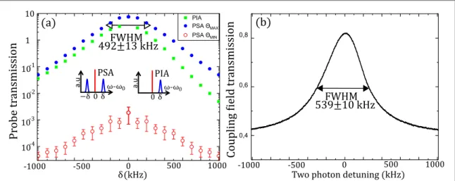
To experimentally test our interpretation of a CPT-enabled PSA process, we measured the probe minimum and maximum transmissions as functions of the detuningδ (see figure5(a)). We compared the phase insensitive
amplification (PIA) configuration, where the +δ signal field is sent alone, with the PSA configuration. In the former case, FWM spontaneously generate an idlerfield, leading to a phase insensitive gain of less than 3. In the latter case, PSA is observed with maximum gains up to 9 dB.
The couplingfield CPT transmission bandwidth can be measured (figure5(b)) by applying a tunable
magneticfield along the propagation axis in the absence of a probe field: the ground levels are then Zeeman shifted, inducing a two-photon detuning, which cancels CPT. The full width at half maximum(FWHM) of the
6
PSA and CPT profiles are comparable, stressing the fact that the coupling field power controls the bandwidth of both processes. One can notice that the CPT resonance does not reach full transparency atδ=0: this is due to the large room-temperature D2transition linewidth W leading to a residual absorption of 12±4%. These losses
also explain that we experimentally have GMAXGMIN< .1
5. Conclusion
In this article, we have shown that the very efficient PSA process that we previously observed in a hot vapor of helium at room temperature[18] is actually enabled by CPT. This process was demonstrated to provide a strong
parametric gain as large as 9 dB for much lower optical depths(green ∼4.5) than in usual alkali vapor setups [14,15,17]. Contrary to these previous works, we have a closed Λ-system which allows to fully exploit the
nonlinearity enabled by CPT. Moreover, we derived a full analytical model to extract the transfer matrix of the probe. It well describes the experimental data and reveals an unusual scaling of the gain. Finally, an original physical picture of this effect could be derived using superpositions of atomic states.
The full transparency of the resonant D1transition allows for efficient FWM involving the detuned D2
transition. Such a CPT-enabled PSA process should be associated to highly squeezed states generation, which will be addressed in a future work. Moreover, the propagation features of the DSP suggest the possibility to store and generate on-demand two-mode squeezed states of light, with the same atoms used recently to demonstrate coherent population oscillation based storage[25]. Although this process is demonstrated in helium 4, our
calculations and the advances on artificial atoms technologies make it possible to imagine systems designed to optimize it.
Acknowledgments
The authors acknowledge funding by Indo-French CEFIPRA agency, Labex PALM(Grant No. ANR-10-LABX-0039-PALM), Région IdF DIM Nano-K, and IUF.
Appendix A. Propagation equation of the signal
The analytical treatment developed in the main text(equations (3) and (4)) is based on the Maxwell–Bloch
equations. The approximation framework is the following:
• The strongest nonlinear processes involving the D2transition are isolated using a perturbative development to
thefirst order in
( )
z G,D .• We assume∣Wp∣∣Wc∣, which legitimates a perturbative expansion atfirst order in Ωp/Ωc.
• We assume ν=ζ=Γ=Δ.
Figure 5.(a) Signal field transmission measured as a function of its detuning δ with respect to the coupling field frequency. Squares: PIA, without input idlerfield. Filled (empty) circles: maximum (minimum) PSA, with an input idler field. Error bars correspond to 1 standard deviation.(b) Measured CPT resonance for the coupling field.
In that regime, using a formal computation software, we derive the following propagation equation for the probe field (equation (12) of the main text):
c c i 1 2 1 1 i 4i 3 2 1 i . A.1 z c p c p c p c 2 * 2 * * n h n z h ¶ + + W - W = DW W W - W W - nz ⎛ ⎝ ⎜ ⎧⎨ ⎩ ⎫ ⎬ ⎭ ⎞ ⎠ ⎟
(
)
∣ ∣ ( )And using equation(5), it is possible to show that
z 0 exp 4i z 3 . c c h W = W D ⎡ ⎣⎢ ⎤ ⎦⎥ ( ) ( )
In order to solve equation(A.1), it is convenient to get rid of this z-dependent phase shift of the coupling field by
introducing the new variableW¢p n,z = Wp n,z exp -4i3 z
h D ⎡ ⎣ ⎤⎦ ( ) ( ) . Atfirst order in ν, we obtain: c c i 1 2 4i 3 . A.2 z c2 p p p * n h h ¶ + + W W¢ = D W¢ - W¢ ⎛ ⎝ ⎜ ⎧⎨ ⎩ ⎫ ⎬ ⎭ ⎞ ⎠ ⎟ ∣ ∣ ( ) ( )
The quantity vg c cos c 1
c 2 2 c 2 a = ´ a= + h W
(
)
( )∣ ∣ is the usual group velocity of a lightfield in CPT (or EIT) conditions. Solving equation(A.2) by considering the real and imaginary parts ofW¢pindependently, onefinally finds L, e 1 i 0, i 0, . p p p L vg i * n m n m n W¢ = -n + W¢ - W¢ ( ) [( ) ( ) ( )]
Then, going back toΩp, onefinally finds the transfer matrix in equation (7), with the additional information that
the propagation is at group velocity vg.
Appendix B. Propagation equation of the DSP
Because EIT is occurring between the dark and bright states of the system, one can then define the DSP by
c
cos p i 2 sin g g.
= aW¢ - h ar+
-Note that the above expression differs from the usual one[24] by the +i factor, which merely comes from the
probe polarization decomposition.
In the same approximation framework as above, the coherence between the dark and bright states writes
2i p c ,
g g
r+ - = - W¢ W∣ ∣
so that´cosa= W¢ . Using the latter relation to express equation (p A.2) in terms ofand*, we get the following DSP propagation equation
z v i 4i 3 . z g * n a h ¶ + = D -⎛ ⎝ ⎜ ⎞ ⎠ ⎟ ( ) ( )
This equation and its complex conjugate can be solved so that we obtainand*at z=L:
L L , , e 1 i e i e i e 1 i e 0, 0, . B.1 L v i i i i i g * * n n m m m m n n = + -+ -n a m m m m -- -⎛ ⎝ ⎜ ⎞ ⎠ ⎟ ⎛ ⎝ ⎜ ⎞ ⎠ ⎟ ⎛ ⎝ ⎜ ⎞ ⎠ ⎟ ( ) ( ) ( ) ( ) · ( ) ( ) ( ) ( )
This equation coincides with equation(7) up to an exponential factor due to the dispersive propagation of the
DSP with thefinite group velocity vg.
References
[1] McKenzie K, Shaddock D A, McClelland D E, Buchler B C and Lam P K 2002 Phys. Rev. Lett.88 231102
[2] Sokolov I and Kolobov M 2004 Opt. Lett.29 703
[3] Lundstrom C, Tong Z, Karlsson M and Andrekson P A 2011 Opt. Lett.36 4356
[4] Levenson J A, Abram I, Rivera T and Grangier P 1993 J. Opt. Soc. Am. B10 2233
[5] Tong Z, Lundstrom C, Andrekson P A, Karlsson M and Bogris A 2012 IEEE J. Sel. Top. Quantum Electron.18 1016
[6] Walls D F 1983 Nature306 141–6
[7] Agarwal G S 2013 Quantum Optics (Cambridge: Cambridge University Press)
[8] Vahlbruch H, Mehmet M, Danzmann K and Schnabel R 2016 Phys. Rev. Lett.117 110801
[9] Corzo N V, Marino A M, Jones K M and Lett P D 2012 Phys. Rev. Lett.109 043602
[10] Fang Y and Jing J 2015 New J. Phys.17 023027
[11] Fang Y, Feng J, Cao L, Wang Y and Jing J 2016 Appl. Phys. Lett.108 131106
[12] Harris S E, Field J E and Imamoğlu A 1990 Phys. Rev. Lett.64 1107
[13] Dantan A, Pinard M and Berman P R 2003 Eur. Phys. J. D27 193–9
[14] Wang S, Ducreay D G, Pina R, Yan M and Zhu Y 2000 Phys. Rev. A61 033805
8