HAL Id: tel-01784871
https://tel.archives-ouvertes.fr/tel-01784871
Submitted on 3 May 2018
HAL is a multi-disciplinary open access archive for the deposit and dissemination of sci-entific research documents, whether they are pub-lished or not. The documents may come from teaching and research institutions in France or abroad, or from public or private research centers.
L’archive ouverte pluridisciplinaire HAL, est destinée au dépôt et à la diffusion de documents scientifiques de niveau recherche, publiés ou non, émanant des établissements d’enseignement et de recherche français ou étrangers, des laboratoires publics ou privés.
Fourier-based reconstruction of ultrafast sectorial images
in ultrasound
Miaomiao Zhang
To cite this version:
Miaomiao Zhang. Fourier-based reconstruction of ultrafast sectorial images in ultrasound. Signal and Image processing. Université de Lyon, 2016. English. �NNT : 2016LYSEI144�. �tel-01784871�
N°d’ordre NNT :2016LYSEI144
THESE de DOCTORAT DE L’UNIVERSITE DE LYON
opérée au sein de
L’Institut National des Sciences Appliquées de Lyon
Ecole Doctorale
N° EDA160
ELECTRONIQUE, ELECTROTECHNIQUE, AUTOMATIQUE (EEA)
Spécialité de doctorat
:Traitement du Signal et de l’Image
Soutenue publiquement le 16/12/2016, par :
Miaomiao ZHANG
Fourier-based reconstruction of
ultrafast sectorial images in ultrasound
Devant le jury composé de :
LOVSTAKKEN Lasse, Professeur des Universités, NTNU Rapporteur PERNOT Mathieu, Directeur de Recherche, Institut Langevin Rapporteur D'HOOGE Jan, Professeur des Universités, KU LEUVEN Examinateur BRIDAL S.Lori, Directeur de Recherche,Université Paris 06 Examinatrice FRIBOULET Denis, Professeur des Universités, INSA-LYON Directeur de thèse BERNARD Olivier, Maître de Conférences, INSA-LYON Co-directeur de thèse
Département FEDORA – INSA Lyon - Ecoles Doctorales – Quinquennal 2016-2020
SIGLE ECOLE DOCTORALE NOM ET COORDONNEES DU RESPONSABLE
CHIMIE CHIMIE DE LYON http://www.edchimie-lyon.fr Sec : Renée EL MELHEM Bat Blaise Pascal 3e etage
Insa : R. GOURDON
M. Stéphane DANIELE
Institut de Recherches sur la Catalyse et l'Environnement de Lyon IRCELYON-UMR 5256
Équipe CDFA
2 avenue Albert Einstein 69626 Villeurbanne cedex [email protected] E.E.A. ELECTRONIQUE, ELECTROTECHNIQUE, AUTOMATIQUE http://edeea.ec-lyon.fr Sec : M.C. HAVGOUDOUKIAN [email protected] M. Gérard SCORLETTI
Ecole Centrale de Lyon 36 avenue Guy de Collongue 69134 ECULLY Tél : 04.72.18 60.97 Fax : 04 78 43 37 17 [email protected] E2M2 EVOLUTION, ECOSYSTEME, MICROBIOLOGIE, MODELISATION http://e2m2.universite-lyon.fr Sec : Sylvie ROBERJOT
Bât Atrium - UCB Lyon 1 04.72.44.83.62
Insa : H. CHARLES
M. Fabrice CORDEY
CNRS UMR 5276 Lab. de géologie de Lyon Université Claude Bernard Lyon 1 Bât Géode
2 rue Raphaël Dubois 69622 VILLEURBANNE Cédex Tél : 06.07.53.89.13 cordey@ univ-lyon1.fr EDISS INTERDISCIPLINAIRE SCIENCES- SANTE http://www.ediss-lyon.fr
Sec : Sylvie ROBERJOT Bât Atrium - UCB Lyon 1 04.72.44.83.62
Insa : M. LAGARDE
Mme Emmanuelle CANET-SOULAS
INSERM U1060, CarMeN lab, Univ. Lyon 1 Bâtiment IMBL
11 avenue Jean Capelle INSA de Lyon 696621 Villeurbanne Tél : 04.72.68.49.09 Fax :04 72 68 49 16 [email protected] INFOMATHS INFORMATIQUE ET MATHEMATIQUES http://infomaths.univ-lyon1.fr Sec :Renée EL MELHEM
Bat Blaise Pascal 3e etage
Mme Sylvie CALABRETTO
LIRIS – INSA de Lyon Bat Blaise Pascal 7 avenue Jean Capelle 69622 VILLEURBANNE Cedex Tél : 04.72. 43. 80. 46 Fax 04 72 43 16 87 [email protected] Matériaux MATERIAUX DE LYON http://ed34.universite-lyon.fr Sec : M. LABOUNE PM : 71.70 –Fax : 87.12 Bat. Direction [email protected] M. Jean-Yves BUFFIERE INSA de Lyon MATEIS
Bâtiment Saint Exupéry 7 avenue Jean Capelle 69621 VILLEURBANNE Cedex
Tél : 04.72.43 71.70 Fax 04 72 43 85 28
MEGA
MECANIQUE, ENERGETIQUE, GENIE CIVIL, ACOUSTIQUE http://mega.universite-lyon.fr Sec : M. LABOUNE PM : 71.70 –Fax : 87.12 Bat. Direction [email protected] M. Philippe BOISSE INSA de Lyon Laboratoire LAMCOS Bâtiment Jacquard 25 bis avenue Jean Capelle 69621 VILLEURBANNE Cedex Tél : 04.72 .43.71.70 Fax : 04 72 43 72 37 [email protected] ScSo ScSo* http://recherche.univ-lyon2.fr/scso/ Sec : Viviane POLSINELLI
Brigitte DUBOIS Insa : J.Y. TOUSSAINT Tél :04 78 69 72 76 [email protected] M. Christian MONTES Université Lyon 2 86 rue Pasteur 69365 LYON Cedex 07 [email protected]
Echocardiography is one of the most widely used modality in real time heart imag-ing thanks to its noninvasive nature and low cost. By providimag-ing dense image volumes in real time, three-dimensional echocardiography can improve the accuracy of the echocar-diographic evaluation of cardiac chamber volumes and be used to assess cardiovascular function and anatomy in various clinical settings. However, the real-time property of three-dimensional echocardiography is still limited in terms of frame rate due to the limited speed of sound. To increase the frame rate, plane wave and diverging wave in transmission have been proposed to drastically reduce the number of transmissions to reconstruct one image. In this thesis, starting with the 2D plane wave imaging methods, the reconstruc-tion of 2D/3D echocardiographic sequences in Fourier domain using diverging waves is addressed. The main contributions are described below.
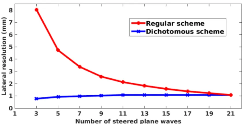
The first contribution of this thesis is to study the influence of the transmission scheme in the context of 2D plane wave imaging. Based on an analytical study, the influence of the transmitted angle sequences and the number of plane waves on the compounded image quality is investigated. A dichotomous transmission scheme is proposed. The efficiency of the different transmission schemes is assessed by evaluating the quality of images recon-structed from the current state-of-the-art plane wave imaging methods. Numerical and experimental results show that the proposed transmission scheme significantly improves the quality of the reconstructed B-mode images at a constant frame rate.
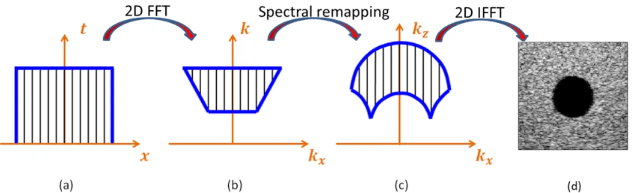
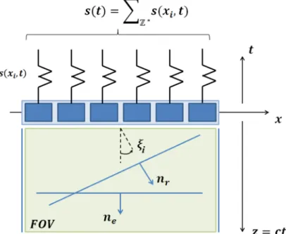
The second contribution concerns the development of an alternative Fourier-based plane wave imaging method (i.e. Ultrasound Fourier Slice Beamforming) by using the concept of steered plane waves both in transmission and in reception. We build a theoreti-cal model to describe the relationship between the echoes and object function based on the Fourier slice theorem. The proposed method is assessed using numerical simulations and experiments, including in vitro and in vivo experiments. Results revealed that the pro-posed method produces very competitive image quality compared to the state-of-the-art Fourier-based and spatial-based methods.
The third contribution concerns the extension of Fourier-based imaging methods from linear to sectorial imaging in 2D by studying the difference between plane wave and di-verging wave transmission in terms of travel time for a given scatterer in the medium and a given transducer element. We derive an explicit spatial transformation which allows deforming the referential Cartesian space insonified by a diverging wave into a dedicated one where the modified medium can be considered as being excited by a plane wave. The performance of the derived approach is evaluated in terms of resolution and contrast from both simulations and in vitro experiments. Comparisons with the current state-of-the-art method illustrate the potential of the derived methods in producing competitive results with lower computational complexity when compared to the conventional delay and sum (DAS) technique.
Finally, the 2D Fourier-based diverging wave imaging methods are extended to 3D by deriving the equivalence between 3D diverging wave and plane wave. Numerical simula-tions are performed to validate and evaluate the proposed method. Results show that the proposed approach provides competitive scores in terms of image quality compared to the DAS technique, but with a much lower computational complexity.
Résumé
L’échocardiographie est une modalité d’imagerie sûre, non-invasive, qui est utilisée pour évaluer la fonction et l’anatomie cardiaque en routine clinique. En fournissant des images volumiques complètes en temps réel, l’échocardiographie en trois dimensions (3D) possède le potentiel afin d’améliorer la précision de l’évaluation des volumes des cavités cardiaques par rapport à l’imagerie 2D et fournit une vue réaliste des valves cardiaques et des anomalies congénitales. En imagerie échocardiographique 3D classique, l’acquisition d’un seul volume avec une qualité raisonnable exige des milliers de faisceaux pour imager le cœur avec suffisamment de détails, ce qui conduit à un fréquence d’imagerie de quelques Hz, ce qui se révèle insuffisant en pratique clinique quotidienne. Afin d’augmenter la fréquence d’image, l’utilisation d’ondes planes ou d’ondes divergentes en transmissinon a été proposée afin de réduire le nombre de tirs nécessaires à la reconstruction d’une image. L’objectif de cette thèse consiste à développer un procédé d’imagerie par ultrasons ultra-rapide en échocardiographie 2/3D basé sur une insonification par ondes divergentes et réalisant une reconstruction dans le domaine de Fourier. Le point de départ était une méthode classique d’imagerie 2D en ondes planes. Les contributions principales obtenues au cours de la thèse sont décrites ci-dessous.
La première contribution de cette thèse concerne l’étude de l’influence du régime de transmission sur la qualité d’image au travers de l’utilisation d’ondes planes en trans-mission. Nous avons présenté un schéma de transmission dichotomique pour l’acquisition linéaire en analysant mathématiquement la pression générée. Nous avons ensuite montré que ce système de transmission peut améliorer la qualité des images reconstruites pour une cadence constante en utilisant les algorithmes de reconstruction conventionnels. La qualité des images reconstruites a été évaluée en termes de résolution et de contraste au moyen de simulations et acquisitions expérimentales réalisées sur des fantômes.
La deuxième contribution concerne le développement d’une nouvelle méthode d’imagerie 2D en ondes plane opérant dans le domaine de Fourier et basée sur le théorème de la coupe centrale. Cet algorithme permet de reconstruire le spectre de l’objet à imager radialement dans le domaine de Fourier. La méthode proposée a été évaluée et comparée avec les méth-odes pour ondes planes existantes au moyen des simulations, d’acquisitions expérimentales réalisées sur des fantômes et in vivo. Les résultats que nous avons obtenus montrent que l’approche proposée fournit des résultats très proches de ceux fournit par les méthodes classiques en termes de résolution latérale et contraste de l’image.
La troisième contribution concerne le développement d’une transformation spatiale explicite permettant d’étendre les méthodes 2D opérant dans le domaine de Fourier d’une acquisition en géométrie linéaire avec des ondes planes à la géométrie sectorielle avec des ondes divergente en transmission. Cette transformation a été obtenue en établissant un isomorphisme en termes de temps de vol lorsque soit une onde divergente soit une onde plane est utilisée en transmission. Les résultats que nous avons obtenus à partir de simulations et d’acquisitions expérimentales in vivo montrent que l’application de cette extension à la méthode de Lu permet d’obtenir la même qualité d’image que la méthode spatiale de Papadacci basée sur des ondes divergentes, mais avec une complexité de calcul plus faible.
Finalement, la formulation proposée en 2D pour les méthodes ultra-rapides opérant dans le domaine de Fourier ont été étendues en 3D. Cela a été réalisé en tenant compte de la coordonnée y dans l’équation du temps vol de l’onde plane et de l’onde divergente. En étudiant la pression obtenue lors de la sommation cohérente des ondes divergentes 3D, un schéma de transmission dichotomique a été proposé dans le but d’améliorer la
Acknowledgment
I would like to thank everyone who gave me their help and support during the past four years of my Master and Ph.D. study in France.
First and foremost, I would like to thank my supervisors Prof. Denis Friboulet, Dr. Olivier Bernard and Prof. Hervé Liebgott. Thanks for giving me this excellent opportunity to work on this exciting project. Your insightful and inspiring guidance, continuous support and encouragement are indispensable to the accomplishment of this thesis, which i cannot express in words. Denis, you are the most enthusiastic person I have ever met. Your patience, enthusiasm and kindness always inspire me to think positive and help me pass through the difficult time. Life seems more colorful with your big smile and laughter. Olivier, your patience and attention to details is unmatched. Thank you so much for all the support and hard work that you have done for me, especially in a time of need. It felt amazing to know that you always had my back. Hervé, your broad knowledge of ultrasound and insight into problems are indispensable to the success of this project. It is really a great experience working with you.
I specially express my thanks to Prof. Lasse Lovstakken and Dr. Mathieu Pernot for reviewing this manuscript and Prof. Jan D’hooge and Dr. S.Lori Bridal for accepting as the jury of my thesis.
I want to acknowledge Olivier Beuf, the director of the lab, for providing us an amazing working environment, surrounded by knowledge and fantastic colleagues. The lab has done and is doing so much amazing research, that i am very happy and proud to be part of it. I would like to thank all my colleagues in the laboratory for their help during my stay in France. Especially, I want to thank Yuemin Zhu, who is responsible for the application program, for his help on all the administrative affairs during my application. I also want to thank François Varray and Lorena Petrusca for the experiment preparation and data acquisition. Emmanuel Roux, thanks for your help on many things during the past four years in France. It was a pleasure being classmates, colleagues and friends with you. Feng Yang, you gave me a lot of useful suggestions both for work and the life. My thanks also go to all the secretaries in the lab for helping me to do all the administrative affairs.
I thank Damien Garcia for providing me his code and in vivo cardiac data.
I would also show my gratitude to China Scholarship Council (CSC) for the financement during my Ph.D. study.
Last but not least, my sincere thanks go to my family for their unconditional love and support in everything I do. Thanks my parents and my parents-in-law for taking care of me and my daughter during this very hard time. No matter where i am and when i need, you are always there to support me. I also would like to express my deepest gratitude to my beloved husband Ge. Thank you for your love, your support and encouragement during our life. To my daughter, Yucheng, thanks for always making me feel like the happiest mom in the world.
Contents
Abstract ii Résumé iii Acknowledgment v Contents ix I Introduction 1 1 Introduction 3 1.1 Motivation . . . 3 1.2 Objectives . . . 6 1.3 Thesis organization . . . 6 II Background 9 2 Echocardiography 11 2.1 Ultrasound image formation . . . 112.1.1 Transducers . . . 11
2.1.2 Wave propagation and interaction with tissue . . . 12
2.1.3 Beamforming . . . 13 2.1.4 Image quality . . . 15 2.2 Imaging modes . . . 16 2.2.1 M-mode imaging . . . 16 2.2.2 Two-dimensional imaging . . . 17 2.2.3 Doppler imaging . . . 17 2.3 Summary . . . 18
3 State of the art: ultrafast ultrasound imaging methods 19 3.1 Ultrafast ultrasound imaging methods . . . 19
3.1.1 Plane wave imaging . . . 20
3.1.2 Diverging wave imaging . . . 25
3.2 Principle of coherent compounding . . . 26
3.3 Motion compensation methods for ultrafast imaging . . . 27
3.3.1 Cross-correlation based motion compensation method for plane wave imaging . . . 28
3.3.2 Doppler-based motion compensation for diverging wave imaging . . 29 vii
III Contributions 33 4 Revisiting the influence of transmission scheme involved in ultrafast
imaging with plane waves 35
4.1 Introduction. . . 35
4.2 Methodology . . . 36
4.2.1 Principles . . . 37
4.2.2 The dichotomous transmission scheme . . . 38
4.3 Experiments. . . 39
4.3.1 Simulation . . . 39
4.3.2 In vitro experiments . . . 41
4.4 Summary . . . 45
5 Ultrasound Fourier Slice Beamforming 47 5.1 Introduction. . . 47
5.2 Theory . . . 48
5.2.1 UFSB: single plane wave imaging . . . 48
5.2.2 UFSB: steered plane wave with compounding scheme . . . 52
5.2.3 UFSB: summary and practical implementation . . . 53
5.3 Numerical simulations . . . 54
5.3.1 Validation of the UFSB method . . . 54
5.3.2 Image quality evaluation. . . 55
5.4 In vitro and in vivo experiments . . . 58
5.4.1 In vitro experiments . . . 58
5.4.2 In vivo experiments of a carotid . . . 59
5.5 Discussion . . . 61
5.6 Summary . . . 64
6 Extension of Fourier-based methods to sectorial imaging in 2D 65 6.1 Introduction. . . 65
6.2 Methodology . . . 66
6.2.1 Extension of Fourier-based techniques to sectorial imaging . . . 66
6.2.2 Reconstructive procedure and practical implementation . . . 70
6.3 Numerical simulations . . . 70
6.3.1 Transmission scheme . . . 71
6.3.2 Validation of the extension model. . . 71
6.3.3 Image quality evaluation. . . 73
6.4 In vitro and in vivo experiments . . . 78
6.4.1 In vitro experiment on CIRS phantom . . . 78
6.4.2 In vivo experiment of a human heart . . . 80
6.5 Discussion . . . 82
6.5.1 Fourier-based methods of sectorial imaging . . . 82
6.5.2 Computational complexity. . . 82
6.5.3 Extension to temporal acquisitions with tissue motion . . . 85
7 3D Ultrafast Cardiac Imaging 87
7.1 Introduction. . . 87
7.2 Extension of the 2D Fourier-based sectorial imaging technique to 3D . . . . 88
7.2.1 3D Fourier-based plane wave imaging methods . . . 88
7.2.2 3D extension of the space transformation introduced in Chapter 6 . 91 7.3 3D diverging wave transmission scheme study . . . 94
7.4 Numerical simulations . . . 97
7.4.1 Lateral resolution. . . 98
7.4.2 Image contrast . . . 99
7.5 Discussion . . . 101
7.6 Summary . . . 101
IV Conclusions and Perspectives 103 8 Conclusions and Perspectives 105 8.1 Conclusions . . . 105 8.2 Perspectives . . . 106 Résumé en français 111 9 Résumé en français 111 Appendix 139 A Appendix 1 139 A.1 Investigation of defocusing effect . . . 139
Publications 141
Bibliography 149
I
Introduction
Chapter
1
Introduction
In this chapter, the motivation of the dissertation work is introduced first. Then the research objectives of this work are outlined. Finally, the organization of the dissertation is presented.
1.1
Motivation
Three-dimensional echocardiography (3DE) is a safe, non-invasive imaging modality, which is used to assess cardiovascular function and anatomy in various clinical settings. This technique improves the accuracy of the echocardiographic evaluation of cardiac cham-ber volumes and gives a realistic view of cardiac valves and congenital abnormalities, which has been conceived as one of the most promising methods for the diagnosis of valvular heart disease [Lang et al. (2006),Monaghan (2006),Shiota (2014)]. However, the current limited frame rate represents a bottleneck for the use of 3DE in daily clinical practice. Indeed, in conventional ultrasound imaging, volumes are constructed by sequentially transmitting beams that are steered in different directions to cover a desired image sector. Assuming that the only limitation to the frame rate is the ultrasound wave propagation, the time needed to construct an image is thus proportional to the number of lines, the image depth and the speed of sound. For soft human tissue, the wave propagation speed is approxi-mately 1540 m/s. With a depth of 200 mm, it takes about 260 µs for a single beam to propagate into the human body and come back. This allows for 3850 transmissions in one second. For cardiac imaging, acquiring a single volume with reasonable quality requires thousands of beams to picture the heart with sufficient details, thus leading to a frame rate around 1 volume per second (Figure1.1a), which is not sufficient in practice. Therefore,
with conventional ultrasound imaging method, although it became readily apparent that 3DE is better suited than two-dimensional echocardiography (2DE) for the assessment of 3D dynamic phenomena, the limited speed of sound still prevents the acquisition of large fields of view at frame rates sufficient to assess the complex dynamics of a beating heart. There are several ways to reach the trade-off between the frame rate and the image quality. One way is to use the technique referred to as parallel receive beamforming to generate several imaging beams in parallel by transmitting broader beams [Shattuck et al. (1984)], which can be achieved by reducing the transmit aperture [Von Ramm et al. (1991),Pavy (1993),Hergum et al. (2007)] and transmitting unfocused or defocused beams [von Ramm et al. (1984),Hasegawa and Kanai (2011)]. In this way, the frame rate can be increased with a factor equals to the number of parallel received beams (Figure
1.1b). However, when increasing the number of parallel received beams, the width of the transmitted beams must be increased accordingly, which results in a lower pressure when the wave propagates at larger imaging depth and, therefore it decreases the image quality (i.e. signal-to-noise ratio and contrast resolution). The image resolution is also degraded due to the increase of the transmitted beam width. In order to maintain high resolution while using fewer broad beams to illuminate the desired field of view, Synthetic Transmit Aperture (STA) imaging has been proposed [Jensen et al. (2006)a]. A single element is used to transmit a spherical wave covering the full image view and all of the elements are used in reception to form a low resolution image. By coherently combining the images from successive transmissions, one may produce transmit dynamic focusing along each line of the final image.
Another way to increase the frame rate is to use multiple transmit beams, called Multi-Line Transmission (MLT). With this technique, several focused ultrasound pulses steered in different lateral directions are transmitted and the same number of image lines are beamformed simultaneously [Shirasaka (1989),Mallart and Fink (1992)]. Using MLT, the frame rate can be M times faster, where M is the number of parallel pulses in each trans-mission. However, the interferences, also known as cross-talk between the simultaneous beams may create artifacts in the resulting image, for instance bright targets can appear in several locations in the image. Various methods have been proposed to reduce the cross-talks by separating the beams either spatially or spectrally [Dubberstein and Von Ramm (2000),Demi et al. (2012),Demi et al. (2015),Denarie et al. (2013)a], using beam trans-formation techniques [Drukarev et al. (1993)], using second harmonic signal [Prieur et al. (2013)] or various apodization schemes [Tong et al. (2013)a,Tong et al. (2014),Tong et al. (2013)b].
The third technique corresponds to the use of ECG gated stitching [Brekke et al. (2007)] to acquire sub-volumes from different cardiac cycles. This is possible because the cardiac activity is a cyclic process. With this method, the sub-volumes acquired from consecutive heartbeats are stitched together to form a full volume and thus it allows to increase the volume size while maintaining the frame rate (Figure 1.1c). Since the sub-volumes come from different heartbeat cycles, the ECG gated stitching is prone to motion
1.1. MOTIVATION
artifacts caused by transducer movement, respiration and varying heart rate [Rabben (2010)].
(a) (b) (c)
Figure 1.1: (Figure 2.1 and 2.3 in [Rabben (2010)]) (a) Real-time 3D imaging: a 60 by 60 degrees volume is acquired in real-time. (b) In 3D beamforming, the beams are steered in both azimuthal (Az) and elevation (El) directions by utilizing all elements of the 2D matrix array. In addition to electronic steering in 3D, current 3D systems are able to perform parallel receive beamforming where the system transmits one wide transmit beam and receives on multiple receive beams (in this case 16 receive beams). (c) ECG gated stitched 3D imaging: sub-volumes from four consecutive heartbeats are stitched together to a 80 by 80 degrees volume.
Several approaches are also proposed to perform high volume rate 3D ultrasound imag-ing [Perrin et al. (2012)b,Skaug et al. (2014)] by reducing the number of transmissions. However, the frame rate reached using the above-mentioned methods is still limited and not sufficient to perform motion and blood flow measurement on the entire volume. In or-der to significantly reduce the number of transmissions, the concept of ultrafast ultrasound imaging has been proposed. This approach uses a smaller number of defocused ultrasound waves in transmission to insonify the entire medium [Tanter and Fink (2014)]. Coherent compounding of the ultrasound image acquired from each transmission allows for a syn-thetic focusing in the full image, as in Synsyn-thetic Transmit Aperture imaging [Jensen et al. (2006)a]. Several approaches were proposed and validated in 2D based on this concept with plane waves (PW) [Lu (1997),Cheng and Lu (2006),Montaldo et al. (2009),Garcia et al. (2013)] and diverging waves (DW) insonifications [Hasegawa and Kanai (2011), Pa-padacci et al. (2014)] for different applications, such as transient elastography [Montaldo et al. (2009)] and cardiac imaging [Hasegawa and Kanai (2011),Papadacci et al. (2014)]. Very recently, Provost et al. demonstrated the feasibility of compounding DW using a sparse virtual array located behind the probe to achieve high frame rates for 3D cardiac imaging [Provost et al. (2014)]. These approaches use PW or DW to insonify the whole medium for each emission. The backscattered echoes are then measured and processed to reconstruct simultaneously all lines of the image of interest either in the Fourier domain [Lu (1997),Cheng and Lu (2006),Garcia et al. (2013)] or in the space domain [Montaldo et al. (2009),Hasegawa and Kanai (2011),Papadacci et al. (2014)]. It has been shown in [Garcia
et al. (2013)] that the computational complexity of the reconstruction process with PW insonifications performed in the space domain is higher than in the Fourier domain.
As far as cardiac imaging is concerned, all the existing ultrafast methods rely on a sectorial configuration associated to DW, due to the limited anatomical access to the heart. Moreover, it is worth to be noted that all the DW-based proposed methods [Hasegawa and Kanai (2011),Papadacci et al. (2014),Provost et al. (2014)] perform reconstruction in the spatial domain, resulting in a higher computational complexity. In order to reduce the computational load in high frame rate echocardiography, therefore, an interesting approach would be to develop a high frame rate imaging method based on Fourier domain with DW insonifications for cardiac imaging both in 2D and 3D.
1.2
Objectives
In the above-described context, the objective of this work is thus to develop a method-ology allowing for 3D ultrafast echocardiographic imaging, based on DW insonification and Fourier domain reconstruction, as well as the careful evaluation of the proposed approach. Starting from 2D PW imaging, the present work proposes to progressively achieve that end by successively addressing the following methodological aspects:
• A new Fourier-based 2D PW imaging method based on the Fourier slice theorem. This algorithm allows the reconstruction of the object spectrum radially and provides an alternative of the current PW imaging techniques in Fourier domain.
• An extension of the 2D Fourier-based PW imaging methods for sectorial imaging with DW in transmission. We propose an explicit transformation by establishing an isomorphism in terms of travel time when either a DW or a PW is used in trans-mission. This formulation allows the reconstruction of wide angle images in Fourier domain with lower computational complexity compared to the current techniques. • A 3D DW imaging method in Fourier domain. The proposed 2D formulation is
extended to 3D. The derived method produces competitive results with much lower computational complexity when compared to conventional delay-and-sum technique.
1.3
Thesis organization
The dissertation is organized as follows:
In Chapter1, the motivation and objectives of this work are introduced. The motiva-tion behind this work is to develop an efficient 3D echocardiography imaging method to increase the frame rates with lower computational complexity. The research objectives of this work are also outlined.
In Chapter 2, the principle of echocardiography is reviewed, including the image for-mation process and the main ultrasound imaging modes used in practice.
1.3. THESIS ORGANIZATION
In Chapter 3, the state-of-the-art ultrafast imaging methods based on PW and DW insonifications are first introduced. To acquire an image of comparable quality as the one obtained using conventional focusing, the principle of coherent compounding is then presented. Finally, the motion compensation methods for ultrafast imaging of moving targets are also presented.
In Chapter 4, the influence of the transmission scheme on image quality is investi-gated. Based on an analytical study of the synthetic pressure, we studied the efficiency of using dichotomous transmission scheme for linear acquisition which allows improving the quality of the reconstructed images at a constant frame rate. The efficiency of the dichotomous transmission scheme is assessed through the use of the current state-of-the-art reconstruction algorithms (introduced in Chapter3) for high frame rate imaging. The quality of the reconstructed images is evaluated in terms of resolution and contrast from both simulations and phantom experiments.
In Chapter 5, an alternative ultrafast PW imaging method (Ultrasound Fourier Slice Beamforming) is proposed based on the Fourier slice theorem, which allows to sample the object spectrum radially in the Fourier domain. With this method, steered PW transmis-sions are used with coherent compounding to improve the image quality (both resolution and contrast) at the expense of image frame rate, like in other previous PW imaging methods. The proposed method is evaluated and compared with the existing PW imaging methods by computer simulations as well as phantom and in vivo experiments.
In Chapter 6, we present the framework that we proposed to extend existing Fourier-based techniques (initially developed for PW imaging) to sectorial imaging using diverging beams in transmission. By studying the difference between PW and DW transmission in terms of travel time for a given scatterer in the medium and a given transducer element, we derived an explicit spatial transformation which allows deforming the referential Carte-sian space insonified by a DW into a dedicated one where the modified medium can be considered as being excited by a PW. The corresponding extended methods are assessed by computer simulations and experiments, including phantom and in vivo experiments of the human heart.
In Chapter 7, the 2D Fourier-based ultrafast sectorial imaging methods are extended in 3D. By studying the synthetic pressure field of the 3D DW compounding, the virtual sources positions are determined to improve the image quality in a fast way. Finally, the extended 3D Fourier-based DW imaging methods are evaluated by numerical simulations and phantom experiments.
In Chapter8, the whole work is summarized, and future studies are suggested.
II
Background
Chapter
2
Echocardiography
In this chapter, we first introduce the conventional ultrasound cardiac image formation process, i.e. the generation and reception of ultrasound waves, the wave propagation in the tissue and the conventional beamforming method. Then the different imaging modes of echocardiography are described.
2.1
Ultrasound image formation
Echocardiography is a diagnostic imaging modality used to visualize the interior of the human heart. It is based on transmitting focused ultrasound pulses from a transducer into the tissue, and then processing the backscattered echoes returning from structures within to form an image of the tissue. This part gives some details on the formation process of such image.
2.1.1 Transducers
Cardiac ultrasound images are usually acquired by using phased array transducers, which consist of a 1D array (or 2D matrix for 3D imaging) of piezoelectric elements that convert electric energy to acoustic pressure, and vice versa. Figure2.1shows the principle of the transducer element transmitting and receiving signals. When transmitting pulses, a voltage of the appropriate frequency is applied to the transducer elements, causing the piezoelectric structures to vibrate and generate ultrasound waves (Figure 2.1a). Upon receival, when the reflected portion of the ultrasound pulse reaches the transducer, the acoustical vibrations induce an electrical signal, which is referred to as the echo signal
(Figure2.1b)andisusedforimageformation.
(a) (b)
Figure2.1: Principleoftransducerelementtransmittingandreceivingsignals. (a)In transmission,thepiezoelectricelementvibratestogenerateasoundwavewhenavoltage isapplied.(b)Inreception,thepiezoelectricelementgeneratesavoltagewhenavibration (anultrasoundwave)applied.
2.1.2 Wavepropagationandinteraction withtissue
Theultrasoundwavesusedfor medicaldiagnosticare mainly mechanicalwavesina longitudinaldirectionwithafrequencyabove20kHzthatisnotaudibletoahumanear. Thewaveispropagatingthroughacontinuousinterchangebetweenthekineticenergyand thepotentialenergyof mediumparticles,whichisrelatedtothedensityandtheelastic propertiesofthemedium[InsanaandBrown(1993),Angelsen(2000)]. Assumingthatthe transmittedultrasoundwavepropagatesinahomogeneous mediumwithoutattenuation, itfollowsthewaveequation[Angelsen(2000),SchmerrJr(2014)]:
∂2p(x,t)
∂t2 =c2∇2p(x,t) (2.1)
wherep(x,t)istheacousticpressureatspatialpositionxontimet,cisthesoundvelocity, whichdependsonthedensityρandthecompressibilityκofthetissueandcanbeexpressed as:
c=√ρκ1 (2.2)
Inechography,forsofthumantissue,cisapproximately1540m/s. Whencisconstant, apulsefromapointsourceyieldsasphericalwavepropagatingwithoutgeneratingany reflectedechoes. However,thisnotthecaseinbiologicaltissues. Whenanultrasound beamistransmittedintothebody,thewaveisprimarilyscatteredandreflectedbecause
2.1. ULTRASOUND IMAGE FORMATION
of the inhomogeneities in tissue density and compressibility. Specular reflections appear when the tissue structures within the body feature boundaries that are much larger than the wavelength. In this case, the amount of reflected echoes depends on the wave inci-dent angle. Whereas a scatterer with size much smaller than the wavelength, the wave is reflected in the form of a spherical wave that does not depend on the incident angle (i.e. diffuse reflection or scattering), which provides much of the diagnostic information in medical ultrasound. The ultrasound wave is also attenuated while propagating in the tissue. This phenomenon is caused by absorption and can be characterized by the atten-uation coefficient. This coefficient is different for each tissue and increases with frequency and propagation distance. Table2.1lists the attenuation coefficients of common biological materials at a frequency of 1 MHz.
Table 2.1: The Impact of Body Tissues on Attenuation (table from
http://usra.ca/tissue.php)
Body Tissue Attenuation Coefficient (dB/cm at 1MHz) Water 0.002 Blood 0.18 Fat 0.63 Liver 0.5-0.94 Kidney 1.0 Muscle 1.3-3.3 Bone 5.0 2.1.3 Beamforming
Classically, the 2D cardiac images (or 3D image volumes) are constructed by succes-sively emitting focused beams that are steered in different directions to cover the desired image sector. The process of steering and focusing the pulses from each transducer element is known as beamforming. In echocardiography, the most commonly used beamformer is delay and sum (DAS), which is shown schematically in Figure 2.2. The idea of DAS is to apply different delays on each piezoelectric element to reach focusing at a given point both in transmission (Figure2.2a) and reception (Figure2.2b).
In transmission, all the piezoelectric elements are excited at different instants (i.e. applying delay τE in Figure 2.2a) which enables the waves coming from all the elements
to reach a desired point at the same time. The distance from each element (xE, yE, zE) to
the focal point (xf, yf, zf) is:
rE = q
(xE − xf)2+ (yE − yf)2+ (zE− zf)2 (2.3)
Then the delay τE that is used on each element of the array can be easily calculated
as:
τE=1c∆rE=1c(max{rE}−rE) (2.4)
wherecisthespeedofsound. Usingsuchdelaysontheelementsenablestogeneratean ultrasoundbeamsteeredandfocusedatanypointinthe medium.
Inreception,allthesignalsreceivedoneachelementaredelayedfirstinthesameway asintransmission(i.e.differentdelaysτE areappliedoneachelementtocompensate
thedifferenceofwavepropagationdistances). Allthedelayedsignalsarethensummed inordertogetthefinalsignalthatcontainsallthecontributionscomingfromthesame pointscattererinthe medium.
(a)
(b)
Figure2.2:Illustrationofdelayandsumbeamformingprocess.(a)Intransmission,pulses fromanarrayofpiezoelectricelementsareappropriatelydelayed(i.e.applyingdifferent τEoneachelement)toachievesteeringandfocusingatadesiredfocalpoint(xf,yf,zf).
(b)Inreception,theechoesreceivedfromapoint(xf,yf,zf)ateachpiezoelectricelement
2.1. ULTRASOUND IMAGE FORMATION
2.1.4 Image quality
The quality of an ultrasound image mainly depends on the spatial resolution (i.e. the axial and lateral resolution) and the contrast resolution (e.g. contrast ratio) of the acquisition system.
Axial resolution
This resolution refers to the minimum distance that can be differentiated between two reflectors located parallel to the direction of ultrasound beam, which is mathematically equal to half the spatial pulse length (i.e. the product of the number of cycles in a pulse of ultrasound and the wavelength λ ) [Ng and Swanevelder (2011)]. The wavelength of a pulse is determined by the ultrasound frequency f with the relation λ = c/f , c is the speed of sound. A higher frequency, therefore, corresponds to a shorter wavelength, thus gives a better axial resolution. Diagnostic medical ultrasonography usually uses transducers with frequencies of 1-20 MHz. However, the attenuation of the wave is greater when the frequency increases, leading to a shorter distance of penetration. Therefore, in echocardiography, in order to penetrate a depth as far as 8-12 cm, a lower frequency (e.g. 2.5 MHz is used for 2D cardiac imaging in this manuscript) is used.
Lateral resolution
This resolution is defined as the minimum distance that can be distinguished between two reflectors located perpendicular to the direction of the ultrasound beam and mainly depends on the width of beam [Ng and Swanevelder (2011)]. However, the width of the beam and hence lateral resolution varies with distance from the transducer. As explained in Section2.1.3, by adjusting the focusing position in the beamforming process, the lateral resolution can be optimal in the region of interest.
Contrast resolution
This resolution is the ability to distinguish between objects with different amplitudes from the background, which is also a critical component in determining the imaging sys-tem’s performance. Although it is determined by the inherent properties of the object, it may be enhanced at various stages in the imaging process, including compression, image memory, and the use of contrast agents [Ng and Swanevelder (2011)]. One definition of the image contrast is the contrast ratio (CR), which can be calculated using the following equation [Wijk and Thijssen (2002)]:
CR = 20 log10q|µt− µb|
(σt2+ σb2)/2
, (2.5)
where µt and µb (σ2t and σb2) are the means (variances) of gray levels in the targets and
the surrounding background, respectively.
2.2
Imaging modes
During the clinical application of echocardiography, three main imaging modes are employed: M-mode (or motion mode) imaging, two-dimensional (2D or B-mode) imaging and Doppler imaging.
2.2.1 M-mode imaging
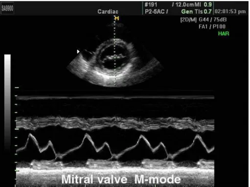
The M-mode (or motion mode) is used to represent the movements of cardiac structures over time (i.e. valve motion, chamber sizes, aortic root size, wall thickness, and ventricular function). It consists in continuously pulsing a single beam through the heart and receiving the echoes from the moving tissue during the cardiac cycle. A M-mode image is obtained by displaying the variation of echoes in position and along time. Since only one beam is used, the M-mode image has a very high temporal resolution, which allows to observe the tissues with very fast movements. To obtain accurate measurements, however, the M-mode beam must be placed at the appropriate locations within the heart. Nowadays, by integrating the 2D and M-mode images, one can send the M-mode beams at the appropriate direction with the guidance of 2D images. Figure 2.3 is an example of the integration of 2D and M-mode images. Firstly, a 2D image is acquired (the top image of Figure2.3) and a single scan line (dotted line) is placed along the area of interest (i.e. the mitral valve). The M-mode will then show the movements of the mitral leaflets over time along the axis of the dotted line (the bottom image of Figure 2.3).
Figure 2.3: M-mode and B-mode images. (top) B-mode image representing a
heart section. (bottom) M-mode representation of the dotted line. Image from
2.2. IMAGING MODES
2.2.2 Two-dimensional imaging
Two-dimensional echocardiography (or B-mode) is the most widespread imaging mode in clinical routine. It consists in scanning a cross-section of the heart using ultrasound beams with different orientations and displaying the received echoes in a two-dimensional image. The position of an echo on the image is determined by its travel time (the depth) and the corresponding beam orientation (the lateral position). Because of the limited access due to the ribs, the shape of an echocardiographic image is a sector (see the top image in Figure 2.3), which allows to scan a wide region from a small access. The final image is displayed on a gray-scale: structures reflecting the ultrasound signal (e.g. valves) are white and non-reflecting (fluids) are black.
2.2.3 Doppler imaging
Doppler echocardiography uses the Doppler principle to determine the flow velocity, direction and characteristics in the heart as well as the velocity of myocardial tissue. A frequency shift occurs when an ultrasound beam interact with a moving targets, such as the red blood cells in the blood. This frequency shift is also related to the transmitted fre-quency of the transducer and the angle between the ultrasound beams and the direction of the moving targets. All these parameters are used to determine the velocity of the moving target. Then by determination of blood flow velocities, Doppler echocardiography allows various hemodynamic evaluations of the heart: transvalvular gradients and intracardiac pressures and shunts; measures of systolic cardiac performance by stroke volume and car-diac output; severity of valvular lesions; measures of diastolic carcar-diac performance; and differentiation between myocardial and pericardial diseases [Anavekar and Oh (2009)].
There are two types of Doppler echocardiography: the continuous wave and pulsed wave Doppler. Continuous wave Doppler can detect the frequency shift of very high velocities, but does not indicate where this shift occurs along the transmission depth. Pulsed wave Doppler uses short bursts or pulses of ultrasound alternating with pauses to detect frequency shift. This technique allows to select Doppler information from a particular location within the heart, but the maximum velocity that can be measured is limited by the pulse repetition frequency.
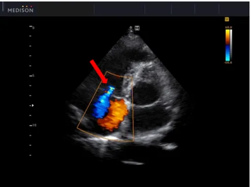
Color flow Doppler echocardiography is based on pulsed wave Doppler principles and displays the velocity of blood flows using a color map. With this technique, multiple sample volumes are analyzed along multiple scan lines. The mean frequency shift obtained from these many sample volumes is color coded for velocity and displayed as color flow superimposed on the 2D image. Conventionally, blood flowing away from the probe is color coded in blue and blood flowing toward the probe in red. A third color, usually yellow or green, shows areas of accelerated or turbulent flow, which is useful for determining valvular regurgitation, visualization of intra-cardiac shunting, or assessment of arterial connections. Figure2.4 gives an example of color Doppler imaging of a mitral regurgitation.
Figure 2.4: An example of color flow Doppler imaging of a mitral regurgitation. Image from http://www.medison.ru/uzi/eho562.htm
2.3
Summary
We described in this chapter the basic concepts involved in the ultrasound image for-mation process, including the way how transducers transmit and receive ultrasound sig-nals, how the ultrasound wave propagates and interacts with the tissue, the beamforming method and the image quality. The three main imaging modes used in clinical are also introduced, i.e. M-mode, B-mode and Doppler mode.
Chapter
3
State of the art: ultrafast ultrasound
imaging methods
In this chapter, we first present the various existing ultrafast ultrasound imaging meth-ods with both PW and DW in transmission. Since the image quality is significantly reduced with a single wave, the principle of coherent compounding is then introduced. Finally, the motion compensation methods for ultrafast imaging of moving targets are also presented.
3.1
Ultrafast ultrasound imaging methods
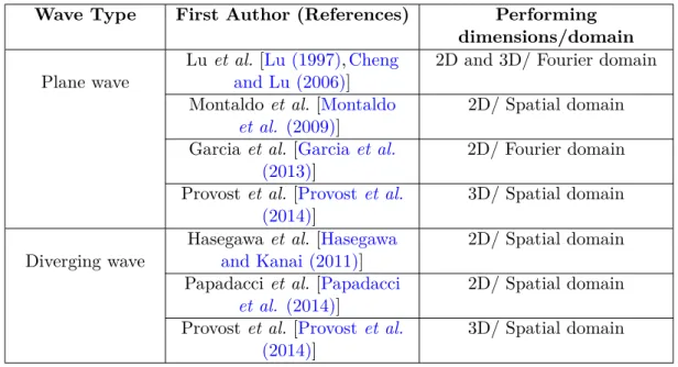
As described in Section 1.1and summarized in [Cikes et al. (2014)], the current state-of-the-art ultrafast cardiac imaging methods include the parallel receive beamforming (also called multiline acquisition (MLA) in [Cikes et al. (2014)]), the ECG gating, the multiline transmit imaging (MLT) and the PW/DW imaging. With the first two techniques, the maximum frame rate reached is still limited (i.e. 2, 4-fold increase in frame rate) because of the degradation of image quality (i.e. lower resolution, stitching artifacts). It was demonstrated in [Cikes et al. (2014),Tong et al. (2014)] that the MLT can gain 12 or 16-fold increase in frame rate without significant loss in image quality when set up adequately. PW/DW imaging are very promising techniques for reaching very high frame rate with controlled image quality. These techniques use PW or DW to insonify the whole medium with one single emission. The backscattered echoes are then measured and post-processed to reconstruct simultaneously all lines of the image of interest. In the following subsections, the existing PW and DW imaging methods will be briefly summarized. An overview of these methods is given in table3.1.
Table 3.1: Overview of existing ultrafast imaging methods based on plane/diverging wave insonifications
Wave Type First Author (References) Performing dimensions/domain Plane wave
Lu et al. [Lu (1997),Cheng and Lu (2006)]
2D and 3D/ Fourier domain Montaldo et al. [Montaldo
et al. (2009)]
2D/ Spatial domain Garcia et al. [Garcia et al.
(2013)]
2D/ Fourier domain Provost et al. [Provost et al.
(2014)]
3D/ Spatial domain
Diverging wave
Hasegawa et al. [Hasegawa and Kanai (2011)]
2D/ Spatial domain Papadacci et al. [Papadacci
et al. (2014)]
2D/ Spatial domain Provost et al. [Provost et al.
(2014)]
3D/ Spatial domain
3.1.1 Plane wave imaging
Lu’s method
Lu et al. developed a 2D and 3D high frame rate imaging method in the late 90s based on the X wave theory [Lu (1997),Lu (1998)], which has been recently extended to include various transmission schemes, such as multiple limited-diffraction beams and steered PW [Cheng and Lu (2006)]. The following is a brief summary of Lu’s method with steered PW in transmission.
Let us assume that there is a 2D array transducer (a 1D array being a special case) located at z = 0 plane and excited to generate steered PW. The received signal for echoes returned from all the scatterers in the medium can be expressed as (see Eq. (7) and (8) in [Cheng and Lu (2006)]): Rkx+kxT,ky+kyT,kz+kzT(t) = Z V f (~r0) h ΦTArray(~r0, t) ∗ ΦRArray(~r0, t) i d ~r0 = 1 2π Z ∞ −∞ A(k)T (k)H(k) c F (kx+ kxT, ky+ kyT, kz+ kzT) e −iwt d k (3.1)
Where f (~r0) is the object function (i.e. the spatial distribution of the reflection
coef-ficient), t is the time, V is the volume of the object and ~r0 = (x0, y0, z0) represents the
coordinates of any spatial point in the object. ∗ represents the convolution, F (·) is the Fourier transform of the object function f (~r0). ~KT = (kxT, kyT, kzT) and ~KR= (kx, ky, kz)
are the wave vectors of the beams in transmission and in reception, with the relation kzT = q k2− k2 xT − k2yT ≥ 0 and kz = q k2− k2
3.1. ULTRAFAST ULTRASOUND IMAGING METHODS
number, w = 2π f is the angular frequency, f is the temporal frequency and c is the speed of the sound in the medium. ΦTArray(~r0, t) and ΦRArray(~r0, t) are the PW in transmission
and reception, where (see Eq.(1) and (5) in [Cheng and Lu (2006)]):
ΦTArray(~r0, t) =
1 2π
Z ∞
−∞
A(k)H(k)eikxTx0+ikyTy0+ikzTz0e−iwtd k (3.2)
and ΦRArray(~r0, t) = 1 2π Z ∞ −∞ T (k)H(k)e
ikxx0+ikyy0+ikzz0e−iwtd k (3.3)
The Fourier transform of ΦTArray(~r0, t) and ΦRArray(~r0, t) are (see Eq.(2) and (5) in
[Cheng and Lu (2006)]): e ΦTArray(~r0, w) = A(k)H(k) c e ikxTx0+ikyTy0+ikzTz0 (3.4) and e ΦRArray(~r0, w) = T (k)H(k) c e ikxx0+ikyy0+ikzz0 (3.5)
Where A(k) and T (k) are the transfer function of the transducer for transmission and reception, H(k) is the Heaviside step function.
By taking the temporal Fourier transform of the received signal Rkx+kxT,ky+kyT,kz+kzT(t) in Eq.(3.1), one can obtain the relationship between the Fourier transform of the object function F (kx0, k0y, k0z) and the Fourier transform of the received echo signals Rek0
x,k0y,kz0(w) (see Eq.(10) and (11) in [Cheng and Lu (2006)]):
e Rk0 x,k0y,k0z(w) = A(k)T (k)H(k) c2 F (k 0 x, k 0 y, k 0 z) (3.6) with: k0x = kx+ kxT k0y = ky+ kyT k0z = kz+ kzT =qk2− k2 x− k2y+ q k2− k2 xT − k2yT ≥ 0 (3.7)
The Eq.(3.6) and (3.7) give a general 3D image reconstruction formula. By setting ky = kyT = 0, one can easily obtain the 2D imaging formula (see Eq.(35) and (36)
in [Cheng and Lu (2006)]): e Rk0 x,kz0(w) = A(k)T (k)H(k) c2 F (k 0 x, k 0 z) (3.8) with: Miaomiao ZHANG 21
k0x = kx+ kxT k0z = kz+ kzT = p k2− k2 x+ q k2− k2 xT ≥ 0 (3.9)
For 2D steered PW with angle θ, kxT = k sin θ, from Eq.(3.9), one can obtain the inverse function (see Eq.(43) in [Cheng and Lu (2006)]):
kx = kx0 − k sin θ k = k0x2+k0z2 2k0 xsin θ+2kz0cos θ (3.10)
From the above Eq.(3.10), the mapping between the Fourier transform of the echo signals in (kx, k) space and the Fourier transform of the object function in (k0x, kz0) space can be done with interpolation. After getting the spectrum of object, by simply taking a 2D inverse Fourier transform, one can obtain the beamformed image.
Garcia’s method
More recently, Garcia et al. proposed a f-k migration method in [Garcia et al. (2013)] for 2D PW imaging based on the exploding reflector model (ERM), which assumes that all the reflectors in the medium explode simultaneously and become upward-emitting acous-tic sources [Gazdag and Sguazzero (1984)]. By using the virtual exploding sources, the ERM can reflect the actual two-way propagation of the acoustic wave accurately. Then by applying the Stolt’s method to find these virtual sources and applying a spatial transfor-mation, the actual scatterers’ positions can be recovered. The following is a brief summary of Garcia’s method with steered PW in transmission.
To make the ERM compatible with the steered PW acquisition, one must fit the hyperbolas of the travel time given by ERM and PW insonifications. For a steered PW with angle θ (see Figure3.1a), the travel time of such a PW to reach a scatterer positioned at (xs, zs) and back to the transducer position x can be characterized by the following
equation (see Eq.(6) in [Garcia et al. (2013)]):
τs(x) = 1 c(sin(θ)(xs− x) + cos(θ)zs+ q (xs− x)2+ z2 s) (3.11)
where c is the wave propagation speed and is assumed constant in the insonified tissues, the (xs− x) operator is used to eliminate the leading zero signals caused by the emission
delays.
3.1. ULTRAFAST ULTRASOUND IMAGING METHODS
Figure 3.1: (Figure 4 in [Garcia et al. (2013)]) Adapting the f-k migration to steered PW imaging. (a) A slant PW is emitted. In this example, the leftmost scatterer is the first to perceive the planar wavefield. (b) The resulting diffraction hyperbolas in the RF echoes are not aligned. (c) Trimming the RF signals realigns the hyperbolas horizontally (from gray to black). (d) A scatterer originally located at (xs, zs) will be moved to (ˆxs, ˆzs) after
the f-k migration.
travel time is (see Eq.(2) in [Garcia et al. (2013)]):
ˆ τs(x) = 1 ˆ c q (ˆxs− x)2+ ˆzs2 (3.12)
By equating τsand ˆτsas well as their first and second derivatives (with respect to x) at
x = xs, provides the following relations (see Eq.(7) and Eq.(9) in [Garcia et al. (2013)]):
ˆ c = √ 1 1+cos θ+sin2θc ˆ zs = (1+cos θ) 3/2 1+cos θ+sin2θzs ˆ xs = xs+2−cos θsin θ zs (3.13)
Thus the ERM can be generalized to model the PW acquisition adequately. The whole process is described in Figure3.1 (see Figure 4 in [Garcia et al. (2013)]).
For a constant ERM propagation speed ˆc, the Stolt’s migration solution can be obtained (see Eq.(14) and (15) in [Garcia et al. (2013)]):
Ψ(x, z, 0) = Z Z ∞ −∞ ˆ cˆkz q kx2+ ˆk2z φ(kx, 0, f (ˆkz))e2iπ(kxx−ˆkzz)dkxdˆkz (3.14) Miaomiao ZHANG 23
with
f (ˆkz) = ˆc sign(ˆkz) q
kx2+ ˆk2z (3.15)
where Ψ(x, z, t = 0) is the wavefield at the time of explosion. φ(kx, 0, f ) is the Fourier
transform of Ψ(x, z = 0, t) over (x, t). Ψ(x, z = 0, t) represents the ERM wavefield on the surface. kx and ˆkz are the spatial wavenumber related to x and z and f is the temporal
frequency.
As shown by Eq.(3.14), the migrated solution is basically the inverse Fourier transform of (see Eq.(16) in [Garcia et al. (2013)]):
ˆ cˆkz q kx2+ ˆkz2 φ(kx, 0, f (ˆkz)) (3.16) Montaldo’s methods
Figure 3.2: (Figure 2 in [Montaldo et al. (2009)]) Schematic representation of the single transmit PW method. (a) The ultrasonic array insonifies the medium using a PW trans-mission. (b) The backscattered RF signals are recorded by the transducer array. (c) The beamforming procedure consists in applying time delays laws and summations to the raw RF signals to focus in the receive mode. Contrary to standard ultrasonography, each line of the image is calculated using the same RF data set but a different set of time delays.
Unlike the methods of Lu and Garcia, Montaldo et al. introduced a 2D time domain PW imaging method which is based on the principle of delay-and-sum (DAS) beamforming [Montaldo et al. (2009)]. Contrary to the conventional ultrasonography, this method allows to reconstruct the entire image simultaneously from only one transmission. The whole process of this method for a single PW is presented in Figure3.2(see Figure 2 in [Montaldo et al. (2009)]). A PW is transmitted into the medium by exciting the transducer elements simultaneously (see Figure 3.2a) and the backscattered echoes RF (x, t) are acquired by each element with the position x (see Figure 3.2b). Then by applying time delays on the raw RF signals and adding coherently, the whole image is obtained (see Figure 3.2c).
3.1. ULTRAFAST ULTRASOUND IMAGING METHODS
For a steered PW with angle θ (see Figure 3.1a), the travel time to the point (xs, zs)
and back to a transducer element placed in x can be expressed as (see Eq.(4) to (6) in [Montaldo et al. (2009)]): τ (x, xs, zs) = 1 c(sin(θ)xs+ cos(θ)zs+ q (xs− x)2+ zs2) (3.17)
Each pixel of the image (xs, zs) is obtained by delaying the RF (x, t) signals with
τ (x, xs, zs) and adding coherently in the transducer direction x (see Eq.(2) in [Montaldo
et al. (2009)]):
s(xs, zs) = Z xs+a
xs−a
RF (x, τ (x, xs, zs))dx (3.18)
The aperture 2a represents the elements that contribute to the signal and can be expressed by the F-number (see Eq.(3) in [Montaldo et al. (2009)]):
F = z
2a (3.19)
where z represents the depth of the image. Ideally, the F-number is constant in the entire image.
3.1.2 Diverging wave imaging
Very recently, Papadacci et al. and Provost et al. proposed to adapt Montaldo’s method to ultrafast imaging with DW in transmission for imaging the heart in 2D [ Pa-padacci et al. (2014)] and 3D [Provost et al. (2014)], respectively. Each transmitted DW is defined by the position of a virtual source located behind the probe and used to insonify the entire field of view. Hasegawa et al. have also proposed a similar approach to perform high frame rate imaging in 2D echocardiography, but using several diverging beams with different directions to cover the entire medium (15 transmits in [Hasegawa and Kanai (2011)]). The beamforming process of the above three methods is also based on the DAS principle, which can be summarized as follows.
If we send a 2D DW with virtual source positioned at (xv, zv), the time to travel to a
point (xs, zs) in the medium and come back to a transducer placed in x is:
τ (x, xs, zs, xv, zv) = 1 c( q (xs− xv)2+ (zs− zv)2+ q (xs− x)2+ zs2) (3.20)
Then a 2D sectorial image can be obtained in the same way as shown in the previous subsection, but with the new delays from Eq.(3.20) in Eq.(3.18).
The above framework can be easily extended to 3D by using a 2D matrix array instead of a 1D probe. In this case, one has to take into account the y-coordinate in Eq.(3.20), and the travel time τ of a 3D DW becomes:
τ (x, y, xs, ys, zs, xv, yv, zv) = 1 c( q (xs− xv)2+ (ys− yv)2+ (zs− zv)2 + q (xs− x)2+ (ys− y)2+ zs2) (3.21)
Then each pixel of the volume (xs, ys, zs) can be obtained by delaying the RF (x, y, t)
signals with τ (x, y, xs, ys, zs, xv, yv, zv) and adding coherently in the two transducer
direc-tions x and y, thus Eq.(3.18) becomes:
s(xs, ys, zs) = Z xs+a xs−a Z ys+b ys−b RF (x, y, τ (x, y, xs, ys, zs, xv, yv, zv))dxdy (3.22)
Where aperture 2a and 2b represent the elements that contribute to the signals in x and y direction, respectively.
Note that a 3D PW can be obtained by a virtual source positioned at infinity behind the probe. Thus the 3D PW imaging can be implemented in the same framework as DW imaging.
3.2
Principle of coherent compounding
The insonification with a single wave (PW or DW) provides the highest frame rate, but comes up with an image quality (defined in terms of resolution and contrast) intrinsically lower than the one obtained with classical multi-line focused beamforming. To overcome this limitation, spatial coherent compounding has been used in all the studies mentioned above to improve image quality. By using several PW of different angles (or DW of different virtual source positions), synthetic focus is achieved in the whole image, as it is done in synthetic transmit aperture (STA) [Jensen et al. (2006)a].
Figure 3.3 shows the principle of coherent PW compounding. Steered PW are sent by the transducer and insonify the whole region of interest. An ultrasound image is computed from each single insonification. The individual image obtained from each PW is a low quality image. The coherent summation of these images creates synthetic focus throughout the image and allows to recover a high quality image. It has been shown in [Montaldo et al. (2009)] that the synthetic focusing reached by coherent compounding is the same as in the standard focusing method for an adequate number of PW (i.e. 71 PW in transmission corresponding to a frame rate of 176 Hz in [Montaldo et al. (2009)]), which allows to have the same image quality in both methods.
Figure 3.4 (Figure 1 in [Papadacci et al. (2014)]) shows the principle of coherent compounding with DW in transmission. Each wave is transmitted individually into the medium (Figure3.4a). By applying adequate delays on each wave, the coherent summation of these waves enables to focus at different depths and lateral positions ((b),(c),(d) in Figure 3.4).
3.3. MOTION COMPENSATION METHODS FOR ULTRAFAST IMAGING
Figure 3.3: Principle of coherent PW compounding. The medium is insonified with steered PW, and the images are reconstructed individually for each PW. The individual images obtained from each PW are low quality images. The coherent summation of these images creates synthetic focusing throughout the complete image and allows to recover a high quality image.
Figure 3.4: (Figure 1 in [Papadacci et al. (2014)]) Principle of coherent compounding with DW. (a) Three DW defined by their virtual source (red crosses at rn ) spaced by a virtual pitch p, are sent independently with a phased array probe directly in contact with the region of interest. Each DW is backscattered by heterogeneities and the array receives the corresponding echo. beamforming is performed, applying delays corresponding to a constructive interference of these DW at the focal point rc . (b) by changing the delay
applied to each of the backscattered echoes from (a), the resulting waves can interfere and virtually focus at different depths, as in (c), and lateral positions, as in (d).
3.3
Motion compensation methods for ultrafast imaging
As described above, the final image produced by ultrafast imaging techniques (based on PW and DW insonifications) are dependent on the coherent summation of images ob-tained from several emissions, thus synthetic focus is achieved in the full image. However, when the scatterers move rapidly between two transmits, a time shift appears in the two
successive received beamformed signals, resulting in a degradation of the image quality during coherent compounding [Wang and Lu (2007)]. When the motion is less than λ /4 (λ representing the wavelength), this time shift can be approximated by a phase shift in the received quadrature-demodulated (IQ) signals [Denarie et al. (2013)b]. For moving tissues, this phase shift must be taken into account during the compounding process to decrease the image artifacts caused by motion.
Several approaches have thus been proposed to tackle this problem in synthetic trans-mit aperture imaging (STAI) [Trahey and Nock (1992),Kim et al. (2002),Oddershede and Jensen (2007),Yiu et al. (2008),Gammelmark and Jensen (2014)]. Very recently, the motion compensation methods adapted to coherent compounding with PW and DW insonifications were investigated in [Denarie et al. (2013)b] and [Poree et al. (2016)], respectively. For both methods, only radial motion (i.e. motion perpendicular to the transducer surface) is considered since lateral motion (i.e. motion parallel to the trans-ducer surface) is expected to have a smaller influence on the image [Wang and Lu (2007)]. The following is a brief summary of the two methods. For more details, the reader is referred to the original papers [Denarie et al. (2013)b,Poree et al. (2016)].
3.3.1 Cross-correlation based motion compensation method for plane wave imaging
In order to reduce the motion artifacts on PW compounded images, Denarie et al. proposed a transmit sequence with angles alternatively negative and positive (i.e. trans-mit angle sequences [−αN, αN, −αN −1, αN −1, . . . , −α1, α1, 0]), which allows reducing the
influence of motion while keeping the same contrast as the classical linear sequences (i.e. [−αN, −αN −1, . . . , −α1, 0, α1, . . . , αN −1, αN]) [Denarie et al. (2013)b]. However, the
pro-posed transmit sequence cannot fully cancel the motion artifacts, so Denarie et al. [Denarie et al. (2013)b] proposed to adapt the cross-correlation method to estimate the motion be-tween each PW acquisition and correct it before coherent compounding. When the motion is sufficiently small, the phase shift between two successive received IQ signals can be ap-proximated to (see Eq.(9) in [Denarie et al. (2013)b]):
∠ xαn+1,m− ∠ xαn,m≈
4π · f0
PRF ·
υrad
c (3.23)
where xαn,m is the IQ signal received for the PW transmitted at an angle αn and beam-formed for the lateral line m, f0 is the demodulation frequency, υrad is the radial velocity
of the scatterers which is assumed to be constant, c is the sound velocity, and PRF is the pulse repetition frequency of the system.
This phase shift can also be estimated by computing the phase angle of the cross-correlation R1n,m between two received beams (see Eq.(10) in [Denarie et al. (2013)b]): ∠ R1n,m =∠ h xFαn,m · xαn+1,mi ≈ ∠ xαn+1,m− ∠ xαn,m (3.24)
![Figure 1.1: (Figure 2.1 and 2.3 in [Rabben (2010)]) (a) Real-time 3D imaging: a 60 by 60 degrees volume is acquired in real-time](https://thumb-eu.123doks.com/thumbv2/123doknet/14528799.723258/17.893.149.788.235.436/figure-figure-rabben-real-imaging-degrees-volume-acquired.webp)
![Figure 3.6: (Figure 5 in [Poree et al. (2016)]) Coherent compounding with integrated MoCo](https://thumb-eu.123doks.com/thumbv2/123doknet/14528799.723258/43.893.165.777.168.321/figure-figure-poree-et-coherent-compounding-integrated-moco.webp)