HAL Id: tel-02909406
https://tel.archives-ouvertes.fr/tel-02909406
Submitted on 30 Jul 2020HAL is a multi-disciplinary open access archive for the deposit and dissemination of sci-entific research documents, whether they are pub-lished or not. The documents may come from teaching and research institutions in France or abroad, or from public or private research centers.
L’archive ouverte pluridisciplinaire HAL, est destinée au dépôt et à la diffusion de documents scientifiques de niveau recherche, publiés ou non, émanant des établissements d’enseignement et de recherche français ou étrangers, des laboratoires publics ou privés.
mobile networks
Zhenzhe Zhong
To cite this version:
Zhenzhe Zhong. Cross-layer congestion control and quality of services in mobile networks. Net-working and Internet Architecture [cs.NI]. Institut Polytechnique de Paris, 2020. English. �NNT : 2020IPPAT022�. �tel-02909406�
N
N
T
:2
02
0I
P
PA
T0
quality of service in mobile networks
Th`ese de doctorat de l’Institut Polytechnique de Paris pr´epar´ee `a Telecom Paris ´Ecole doctorale n◦626 ´Ecole Doctorale de l’Institut Polytechnique de Paris (IP Paris)
Sp´ecialit´e de doctorat : Informatique, Donn´ees et Intelligence Artificielle
Th`ese pr´esent´ee et soutenue `a Palaiseau, le 15/07/2020, par
Z
HENZHEZHONG
Composition du Jury : Isabel Amigo
Assistant Professor,IMT Atlantique Pr´esident
M.Lyes Khoukhi
Professeur,University of Technology of Troyes Rapporteur M.Pascal Lorenz
Professeur, University of Haute Alsace Rapporteur
Dominique Gaiti
Professeur, University of Technology of Troyes Examinateur St´ephane Tuffin
Gestionnaire de projet, Orange Labs Examinateur
Isabelle Hamchaoui
ing´enieur de recherche senior, Orange Labs Directeur de th`ese(CIFRE) Ahmed Serhrouchni
Professeur, Telecom ParisTech Directeur de th`ese
Rida Khatoun
List of figures 5
List of tables 9
List of Abbreviations 18
1 Introduction 21
1.1 Context and Objective . . . 21
1.2 Contributions . . . 24 1.3 Thesis outline . . . 25 2 Introduction en Français 27 2.1 Contexte et objectif . . . 27 2.2 Contributions . . . 30 2.3 Aperçu de la thèse . . . 32
3 Overview of Mobile network architecture and congestion control algorithms 33 3.1 Introduction . . . 33
3.2 LTE mobile network . . . 34
3.2.1 LTE backhaul . . . 34
3.2.2 LTE Radio Access Network . . . 35
3.3 End-to-End Congestion control methods for Quality of Service . . . 41
3.3.1 Non-Cross-Layer protocols . . . 42
3.3.2 Cross-layer protocols . . . 52
3.3.3 Other solutions . . . 58
3.4 Discussion and conclusion . . . 59
4 Models and Tools used in Congestion Control Algorithms 63 4.1 Introduction . . . 63
4.2 Design logics in a Congestion Control Algorithm: a TCP example . . . 63
4.3 TCP Transmit/Receive Sequence Trace figures . . . 66
4.4 The STARTUP procedure in bottleneck bandwidth and round trip delay-based congestion control . . . 69
4.5 DupAck procedure for the lower bound to confirm a trend . . . 71
4.6 BURSTY traffic and PACING traffic . . . 72
4.7 Conclusion and discussion . . . 77
5 Adapt Channel Quality Indicator Control and Bottleneck Bandwidth and RTT congestion control in LTE network in NS3 simulator 79 5.1 Introduction . . . 79
5.2 TCP BBR . . . 80
5.2.1 BBR state machine . . . 80
5.2.2 BBR capacity estimation . . . 82
5.3 From CQIC in 3G to DCIC/TCP-CQIC-LTE . . . 82
5.3.1 QUIC-CQIC in HSPA+ . . . 82
5.3.2 DCIC/TCP-CQIC in LTE . . . 84
5.3.3 Why Delayed ACK . . . 87
5.4 DCIC/TCP-CQIC implementation on NS3 . . . 89
5.5 DCIC/TCP-CQIC-LTE v.s. TCP Westwood and Cubic . . . 90
5.5.1 Result and discussion . . . 91
5.6 DCIC/TCP-CQIC v.s. TCP BBR . . . 95
5.7 Conclusion . . . 98
6 Toward client driven bandwidth estimation architecture for end-to-end conges-tion control: a protocol design 101 6.1 Introduction . . . 101
6.2 The pros and cons of tested CCAs . . . 102
6.3 Bandwidth estimation method in UE . . . 104
6.3.1 Principle of design . . . 104
6.3.2 Validate CDBE BWE method with saturated traffic . . . 107
6.4 CDBE state transition module in server . . . 107
6.4.1 State definition and impact of parameters . . . 109
6.4.2 Condition of state transition in CDBE server . . . 111
6.5 Simulation and result discussion . . . 113
6.5.1 Simulation configuration . . . 113
6.5.3 Per-flow analysis . . . 116
6.5.4 System level result statistics, evaluation and discussion . . . 116
6.6 Conclusion . . . 118
7 CDBEv2: Toward ubiquitous congestion control in a mobile network 121 7.1 Introduction . . . 121
7.2 From CDBE to CDBEv2 . . . 122
7.2.1 Simplified Client-Side bottleneck bandwidth estimation . . . 122
7.2.2 Server Side Windowed BWE report utilisation with a dynamic low-pass filter . . . 123
7.2.3 Advanced features in CDBEv2 state machine . . . 126
7.2.4 Simulation and analysis of CDBEv2 . . . 142
7.3 Conclusion and future work . . . 153
8 Conclusion and Future work 159 8.1 Thesis conclusion . . . 159
8.2 Perspectives and future direction . . . 161
1.1 Goals and tradeoffs for an ubiquitous CCA design . . . 23
2.1 Objectifs et compromis pour une conception CCA omniprésente . . . 30
3.1 LTE interface stacks . . . 34
3.2 Capacity variation in different generations of Cellular network . . . 37
3.3 Brief LTE protocol stack . . . 40
3.4 Simplified LTE Network architecture with RAN, backhaul and gateway . . . 41
3.5 Categories of congestion control solutions . . . 42
3.6 Illustrate the basic concept behind loss-based congestion control . . . 45
3.7 Illustration of ITCP . . . 50
3.8 Illustration of MTCP . . . 51
3.9 Mobile throughput Guidance . . . 51
3.10 CQIC Flowchart . . . 53
3.11 Improved CQIC Flowchart . . . 54
3.12 piStream flowchart . . . 55
3.13 Time consumption in different section of a Mobile edge network . . . 60
3.14 Goals and tradeoffs for an ubiquitous CCA design . . . 60
4.1 Abstract of the network assumption in the thesis . . . 64
4.2 Compare the target operating point and area of loss-based Congestion control and bandwidth/round trip delay based control algorithm . . . 65
4.3 Reading the TCP Trace figure . . . 67
4.4 Rough working pattern of Loss-based congestion control. . . 68
4.5 Simplest case for 3 Dupack . . . 72
4.6 Birth-death process of a M/M/1 Queue model . . . 74
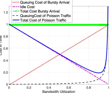
4.7 Bandwidth utilisation against the cost in time for poisson type of traffic and bursty traffic . . . 75
4.8 Cost of idle, queuing and sum of the two when the pacing data rate is equivalent
to bottleneck bandwidth . . . 75
4.9 The effect of pacing in a network. . . 76
4.10 Recalling goals and objectives . . . 78
5.1 Case study example of CQIC and BBR . . . 83
5.2 DCI in LTE radio link . . . 84
5.3 Compare CQIC method and DCIC method . . . 85
5.4 Capacity difference among PHY, RLC and estimations . . . 88
5.5 CQIC Header report design. . . 89
5.6 Average Throughput(a), and(b)Average Round Trip Time . . . 91
5.7 Throughput Cumulative Distributive Function of1MB(a),10MB(b) download 92 5.8 RTT cdf of 1MB(a),10MB(b) download . . . 92
5.9 (a),Average RLC UL re-transmission (per UE) and (d)Average RLC UL re-transmission (per UE) . . . 93
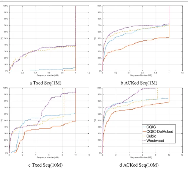
5.10 The Maximum sequence of transmitteda,cand ACKed data sequenced,b . . . 94
5.11 DL, UL and End-to-End traffic . . . 97
6.1 Illustration of CDBE filter function on UE . . . 105
6.2 Fixed network topology for CDBE BWE validation . . . 107
6.3 Validate CDBE BWE method in a wired network with UDP traffic . . . 108
6.4 Validate CDBE BWE method in LTE with UDP traffic . . . 108
6.5 CDBE server state transition . . . 109
6.6 Bandwidth estimation (left), Gain, DSDL and DSDLmin in one experiment (right) . . . 113
6.7 Simulation topology and concept illustration . . . 114
6.8 (a) Goodput CDF of CDBE, CQIC, CQIC-S and BBR and (b) RTT samples with 75% and 99% percentiles . . . 119
7.1 The structure of BW option field in TCP header. . . 123
7.2 How does β change with RTT on interval RT Tmin∈ [20ms, 300ms] . . . 125
7.3 Queuing delay caused by STARTUP stage for Gpacing = 2, 2.77, 2.88 with BW(t0) = 1Mbps . . . 129
7.4 Overall mean delay for initial bandwidth from 100Kbps to 1Mbps and the STARTUP Gain from 2 to 3 respectively. . . 130
7.5 The the mean, maximum, minimum delay and lost percentage caused by different pairs of Gpacingand BW (t0) for BWBtlnck∈ [1Mbps, 150Mbps] . . . 131
7.6 The the mean, maximum, minimum delay and lost percentage caused by different pairs of Gpacingand BW (t0) for BWBtlnck∈ [150Mbps, 500Mbps] . . 132
7.7 Summary of STARTUP Gain pair selection . . . 133
7.8 Performance of thresholds, evolution of BW0/BW1and Queue size in bottlneck
in BWBtlnck = 1Mbps . . . 136
7.9 Performance of thresholds, evolution of BW0/BW1and Queue size in bottlneck
in BWBtlnck = 1Mbps . . . 137
7.10 Performance of thresholds, evolution of BW0/BW1and Queue size in bottlneck
in BWBtlnck = 5Mbps . . . 138
7.11 Performance of thresholds, evolution of BW0/BW1and Queue size in bottlneck
in BWBtlnck = 20Mbps . . . 138
7.12 Performance of thresholds, evolution of BW0/BW1and Queue size in bottlneck
in BWBtlnck = 150Mbps . . . 139
7.13 Performance of thresholds, evolution of BW0/BW1and Queue size in bottlneck
in BWBtlnck = 500Mbps . . . 140
7.14 State transition of CDBEv2 with features of each states . . . 142
7.15 Trajectory of moving mobile device for mobile simulation case 2. . . 143
7.16 State transition, BIF and thresholds variations for two flows in simulation. Left: Flow1 from 1s-4s;Middle:Flow1 from 4s-7s;Right: Flow2 from 4s-7s RT Tmin=60ms BWBtlnck= 20Mbps . . . 143
7.17 Performance of complete CDBEv2 for varying BWBtlnck, RT Tmin=24ms, 2
flows. Top left:Bandwidth variation; Top right:share of Bandwidth of two flow; bottom left:RTT variation; bottom right:BW utilization and Fairness of BW share; . . . 144
7.18 Performance of complete CDBEv2 for varying BWBtlnck, RT Tmin=24ms, 4
flows. Top left:Bandwidth variation; Top right:share of Bandwidth of two flow; bottom left:RTT variation; bottom right:BW utilization and Fairness of BW share145
7.19 Bandwidth performance in Fixed network with different configurations. Left column: Deep Drain Limit is 10. Middle column: Deep Drain Limit is 5. Right column: Deep Drain Limit is 5 with Growth compensation. RT Tmin=24ms. . 146
7.20 RTT performance evolution in Fixed network 7 flows.RT Tmin=24ms. . . 147
7.21 Bandwidth performance in Fixed network: Left column: DDL=5 + GC. Right column: DDL=5 + GC + FQM. RT Tmin=24ms. . . 147
7.22 Bandwidth performance in Fixed network: First row: BWBtlnck = 20Mbps.
Second row: BWBtlnck = 150Mbps. RT Tmin=24ms, 120ms and 300ms for 1st,
7.23 Performance of complete CDBEv2 for BWBtlnck =20Mbps, RT Tmin=24ms . . 149
7.24 Performance of complete CDBEv2 for BWBtlnck =20Mbps, RT Tmin=120ms . 150
7.25 Performance of complete CDBEv2 for BWBtlnck =20Mbps, RT Tmin=300ms . 151
7.26 Receiving Data Rate(above) and RTT(bottom) performance of CUBIC, BBR, CDBEv2 in LTE network: constant position . . . 152
7.27 Receiving Data Rate(above) and RTT(bottom) performance of CUBIC, BBR, CDBEv2 in LTE network: predefined trajectory . . . 152
7.28 Average Goodput(left), RTT(middle) and FairnessIndx(right) performance for Stand still and Trajectory moving cases . . . 153
7.29 Statistics of Goodput(left) , RTT(middle) and fairness(right)t for BBR, CD-BEv2 in LTE network: 40 sets of different random initial location and random trajectory . . . 153
7.30 Performance of complete CDBEv2 for BWBtlnck =150Mbps, RT Tmin=24ms . 155
7.31 Performance of complete CDBEv2 for BWBtlnck =150Mbps, RT Tmin=120ms 156
3.1 Difference among 2G 3G and 4G mobile radio link(typical values) . . . 38
3.2 Summary of non cross-layer E2E solutions . . . 49
3.3 Summary of non-cross-Layer middle box solutions . . . 52
3.4 Summary of novel e2e solutions . . . 56
3.5 Cross-Layer middle box solutions . . . 58
3.6 Merit of the solutions . . . 59
5.1 Simulation Configuration for DCIC/TCP-CQIC validation . . . 90
5.2 Compare the DCIC versions with BBR . . . 95
5.3 Pros and cons of using DCIC(TCP-CQIC)/BBR . . . 98
6.1 Compare the technical details in the baselines and DCIC . . . 103
6.2 Simulation Configuration for CDBE validation . . . 115
6.3 Compare the CDBE with Baselines . . . 115
3.1 Vegas congestion avoidance logic . . . 46
3.2 DupAck in Westwood . . . 47
3.3 RTO in Westwood . . . 48
7.1 Update BW (ti) in use . . . 124
BWBtlnck Bottleneck Bandwidth RT Tmin Minimum Round Trip Time 3GPP 3rd Generation Partnership Project ACK Acknowledgement
ADD Asymmetric Deep DRAIN ADD asymmetric Deep Drain AM Acknowledgement mode
AM Client Driven Bandwidth Estimation AMC Active Queue Management
AMC Adaptive Modulation and Coding APP APPlication(Layer)
BBR Bottleneck Bandwidth and RTT BIF Bytes In Flight
BLWR Block Error Rate BN Bottleneck
BW Bandwidth
BWE Bandwidth Estimation
CCA Congestion Control Algorithm CDBE Client Driven Bandwidth Estimation
CDBEv2 Client Driven Bandwidth Estimation version 2 CDF Cumulative distribution function
CQI Channel Quality Index CQIC CQI Congestion Control CWND Congestion WiNDow
DCI Downlink Control Information
DD Deep DRAIN
DD Deep Drain
DL (Mobile) Downlink DS Download Stream/Flow DTX Discontinuous Transmission DUPACK Duplicated ACK
E2E End-to-End
ECN Explicit Congestion Notification EDGE Enhanced Data for GSM Evolution EMM EPS Mobility Management
EPC Evolved packet core EPS Evolved packet system ESM EPS Session Management
EUTRAN Evolved Universal Terrestrial Radio Access Network FIFO First in, First Out
FQ Fair Queue FQM Fair Quit Method FRecv Fast Recovery FReTx Fast Retransmission GC Growth Compensation GC growth compensation
GPRS General Packet Radio Service GSM Global system for Mobile GTP GPRS Tunneling Protocol
HARQ Hybrid Automatic Repeat ReQuest HSDPA High Speed Downlink Packet Access HSPA High Speed Packet Access
IETF Internet Engineering Task Force IP Internet Protocol
ISG Industry Specification Group ITCP Indirect-TCP
ITU International Telecommunication Union KB Kilo-Bytes
Kb Kilo-bits
KBps Kilo-Bytes per second Kbps Kilo-bits per second L1 Layer 1(Physical layer)
L2 Layer 2(MAC layer)
LEBAT Low Extra Delay Background Transport LTE Long-Term Evolution
M-TCP Tcp for Mobile cellular networks MAC Medium Access Control
MBps Mega-Bytes per second Mbps Mega-Bits per second MBR Maximum Bit Rate
MCS Modulation and Coding scheme METP Mobile End Transport Protocol MIMO Multiple Input Multiple Output MME Mobile Management Entity MSR Mobility Support Router MTCP Mobile TCP
NACK Negative-ACK NAS Non-Access Stratum NIN Non-IP-Networking NS3 Network Simulator 3
OFDM Orthogonal Frequency Division Multiple
OFDMA Orthogonal Frequency Division Multiple Access PDCP Client Driven Bandwidth Estimation
PDN Packet Data Network
PEP Performance Enhancement Proxy PF Proportional Fair
PGW Packet Data Network Gateway PHY PHysical layer
piStream Physical layer informed adaptive video streaming over lte Pkt Packet
PLR Packet Loss Ratio QCI QoS Class Identifier QoE Quality of Experience QoS Quality of Service
QUIC Quick UDP Internet Connections RAN Radio Access Network
RB Resource Block
RBG Resource Block Group RFC Request For Comment RLC Radio Link Control RRC Radio Resource Control RRM Radio Resource Management RTO Re-transmission TimeOut RTT Round Trip Time
SACK Selective ACK
SCTP Stream Control Transmission Protocol SGW Serving Gateway
SINR Signal to Interference plus Noise Ratio ssthresh Slow Start Threshold
TBS Transport Block Size TCP Transport Control Protocol TM Transparent Mode
TTI Time Transmission Interval UCI Uplink Control Information UDP User Datagram Protocol UE User Device
UL (Mobile) Uplink
UM Un-Acknowledgement Mode
UMTS Universal Mobile Telecommunications System US Upload Stream/Flow
WCDMA Wideband Code Division Multiple Access WebRTC Web Real-Time COmmunication
Conference Papers:
• Zhenzhe Zhong, Isabelle Hamchaoui, Rida Khatoun: Perils of using cqic in lte network and a quick fix with delayed ack. –15th IEEE Annual Consumer Communications & Networking Conference (CCNC), January 2018, Las Vegas, USA
• Zhenzhe Zhong, Isabelle Hamchaoui, Rida Khatoun, Ahmed Serhrouchni: Performance evaluation of cqic and tcp bbr in mobile network. –21st Conference on Innovation in Clouds, Internet and Networks and Workshops (ICIN), February 2018, Paris, France • Zhenzhe Zhong, Isabelle Hamchaoui, Alexandre Ferrieux, Rida Khatoun, Ahmed
Serhrouchni: CDBE: A cooperative way to improve end-to-end congestion control in mobile network. –2018 14th International Conference on Wireless and Mobile Computing, Networking and Communications (WiMob), October 2018, Limassol, Cyprus
Journal Paper In preparation:
CDBEv2: toward better end-to-end performance in mobile network. –To be submitted to a journal
Introduction
This thesis aimed to address the congestion control issue in mobile radio access networks with a cross-layer method, and finally proposed a ubiquitous solution for a mobile network.
1.1
Context and Objective
The mobile network consists of radio access network with cells to serve user devices, packet core network for traffic delivery and gateways which connect to other parts of the whole internet.
From the second generation (2G)[1] of commercial mobile networks to the widely deployed Long Term Evolution (LTE, also known as 4G)[2] nowadays, the capacity of a mobile radio access network experienced explosive multiplication thanks to the progress of advanced radio techniques. The peak PHY[3] layer capacity has increased from tens of Kilo-bits per second (Kbps) level up to hundreds of Mega-Bits per second (Mbps) level in each Transmission Time Interval (TTI). Furthermore, thanks to the dynamic Modulation and Coding Scheme (MCS), Multiple-Input Multiple-Output (MIMO)[4]. More advanced wireless technologies are applied to fifth-generation(5G) of the Mobile network: massive MIMO antennas, wide spectrum bandwidths, multi-band carrier aggregation, etc.. Plus the corresponded media access(MAC) layer and the Radio Link Control layer on the Radio access network (RAN), the mobile network nowadays can provide the theoretical bandwidth ranging from Kbps up to Gbps in a short period. Such agility allows LTE, 5G and the following generations of mobile networks to support a wide variety of mobile networking applications in daily life.
Apart from Cellular part, the backbone infrastructures are the special type of fixed network with layered design. User data flows from the outside source (remote server or CDN server) to packet delivery network (PDN) gateways (PGW), then finally sent to the user equipment (UE) through RAN. The under-utilisation of RAN is a long-standing problem3.1. The upper
layers which take care of end-to-end traffic transportation in a mobile network should have the adaptability to utilise the ever-mounting capacity better. Our focus is to address the issue from the perspective of congestion control design in transport-layer.
In this thesis, we are going to:
1. understand the reason behind this underutilisation in a mobile cellular network, 2. explore the existing solutions and test their performance in the network
3. design algorithms, protocols or architectures of congestion control to improve the end-to-end performance and analysis the pros and cons of the proposed algorithm
There are three types of design logic in a congestion control algorithm on the transport layer. They are loss-based congestion control, delay-based congestion control and latest bandwidth-delay based congestion control. Concerning the bandwidth utilisation, loss-based method trades the utilisation with loss, as the extreme form of delay in a buffered network. Delay-based methods trade utilisation with different amount of delay. The bandwidth-delay based CCA, as succeeder delay-based methods, balances the bandwidth utilisation and delay by frequent probing and draining operation on the time domain.
Apart from the Transport layer oriented CCAs, there are also several cross-layer attempts to invoke the lower layer information to improve the bandwidth utilisation. In our review, we focus only on the end-to-end cross-layer solutions on a wireless network.
In the current mobile network, the conventional TCP/IP loss-based algorithm is still the main-stream. A new Industry Specification Group Non-IP-Networking (ISG NIN)[5] of European Telecommunications Standards Institute (ETSI) also working toward looking for a replacement of conventional TCP/IP in the 5G core network since we are tired of the bufferbloat phenomenon caused by the loss-based CCA.
The congestion control architecture we are going to design is on an end-to-end basis, which takes the nature of a mobile cellular network into consideration. The assumption is that all the incoming traffic will flow through the PGW, and the PGWs can guarantee the CCA in the whole mobile backbone. Hence we can design a transport layer end-to-end congestion control algorithm to guarantee the fair share of capacity in both mobile backbone and RAN.
These conventional and lately proposed CCAs are the origin of this thesis topic: To find out whether the cross-layer design like CQIC is suitable for the full mobile network. After the validation and the evaluation of CQIC, one the one hand, we need to decide whether to follow the explicit CQIC manner or introduce an implicit bandwidth estimation. On the other hand, the cooperated congestion control architecture, which was not well introduced on the CQIC server, should also be proposed, so that the server has the capability of probe more, relief the congestion and equally share the bottleneck bandwidth.
Hence this PhD thesis aims to study and propose innovative Congestion control mechanism or Architecture to improve network utilisation and customer experience on mobile networks.
The method we are going to follow and the objectives of the thesis are:
• Review the existing CCA algorithms and the features of mobile network and analyse their feature in mobile network
• Review the cross-layer proposals for mobile networks and perform a brief evaluation of these mechanisms,
• Implement and review the latest BBR in NS3[6] simulator as the baseline for the compar-ison
• Propose and design an innovative CCA architecture for 3G and 4G networks,
• Derive a model and evaluate the performance of these architectures and develop required functions, and
• Implementation and evaluation of the proposed CCA
Fig. 1.1 Goals and tradeoffs for an ubiquitous CCA design
Overall, the design of the CCA in this thesis use the goal and tradeoff shows in Fig.2.1as the principle. So based on these facts and assumption, we have these design trade-offs to guild our research.
The challenge for utilisation mainly comes from the real-time variation of RAN capacity. The challenge for the delay and loss is mainly caused by buffer size management. Note that loss is the extreme expression of delay.
The simplicity is also our concern since the mobile device has limited processing power and limited battery life.
Fairness is the essential goal of the equilibrium of distributed CCA would like to achieve. Last but not least, Genericity is the special requirement for a CCA running in a hybrid network like mobile network since the bottleneck can be anywhere such as RAN or the wired backhaul.
Simply speaking, the goal is to design a simple (to save computation power) CCA to improve the radio resource utilisation with the cost of minimum delay and loss in the whole mobile network. Step by step this thesis should achieve the goals on the tradeoffs in the following chapters.
1.2
Contributions
Based on the objectives, we decide to use the NS3 simulator to validate the existing CQIC algorithm and transplant the algorithm from 3G versions to 4G versions, to compare the performance of CQIC and traditional TCP CCAs. Furthermore, the most recent TCP BBR is implemented in NS3 simulator. Based on these advance work, the pros and cons of using CQIC and BBR are identified. Besides, based on the discovery of the earlier-mentioned work, an efficient cooperative CCA architecture is proposed. Though the proposed algorithm is not explicitly invoking information from the lower layer(MAC/PHY), but it achieves similar performance. More specifically, the performance of the proposed algorithm achieves better downstream (DS) delay (DSDL) compared to BBR and CQIC and has slightly worse goodput and DS throughput compared to CQIC. Furthermore, an improvement on the state machine is proposed with the configuration and the details analysed by proposed models. The improvement allows the state machine to achieve BW fair share in the fixed network and to have lower average RTT than BBR on the mobile network.
The contributions of this thesis are as follows:
□ Identify the main feature of the conventional congestion control in both wired and mobile network. The features are implemented and validated by NS3 simulator.
□ Identify the main feature of the existing CQIC algorithm and find a solution to release the congestion caused by original CQIC. An NS3 version of CQIC, named DCIC, is implemented.
□ Introduce a state transition mechanism on server side for DCIC to complete the congestion control logic.
□ Introduce the client slide bandwidth estimation concept into the congestion control design.
□ for simplicity CDBE:Designed a prototype of Client-side Driven Bandwidth feedback loop is built and tested.
□ Toward ubiquitous congestion control:1.Improve the state transition method in server-side to achieve BW fair share in the hybrid network. 2. Simplify the BW estimation for prototype.3. Introduced a parameter analysis method to achieve a low-delay/loss equilibrium for the startup of newcomer flows.
The future direction of this research can be the validation of TCP friendliness and further deploy CDBEv2 in a real network to further debug and enhance the capability of a faster fair BW share merge. The possibility of using RTT instead of DSDL remains to be validated since, in our assumption, the congestion only happens in the downstream, and the asymmetric Uplink and Downlink capacity is harmful to RTT based decision making. Furthermore, investigate the performance during the handover period, and high-speed mobility to the validation of the proposed CCA is also of our interest.
1.3
Thesis outline
The rest of the thesis is organised as follow: In Chapter3, background on LTE mobile network and CCAs in end-to-end data transport are presented. A brief overview of the baseline CCAs, CQIC and BBR, is also described. The design principle for trade-off, necessary tools for analysis, network models and the general philosophy of CCAs are demonstrated in Chapter
4. The detailed comparison of between CQIC and baseline algorithms is shown in Chapter
5. The CQIC-s, which is CQIC, with state transition manner on server-side, and the BBR are also compared in this chapter. A novel CCA architecture is proposed in Chapter6, and the performance is tested against the baselines. The improvement of this prototype architecture, CDBEv2, is proposed tested and validated in Chapter 7. The conclusion of this thesis is conducted in Chapter8. Future works and the perspectives are also presented in this chapter.
Introduction en Français
Cette thèse visait à aborder le problème du contrôle de la congestion dans les réseaux d’accès radio mobile avec une méthode cross-layer, et a finalement proposé une solution omniprésente pour un réseau mobile.
2.1
Contexte et objectif
Le réseau mobile se compose d’un réseau d’accès radio avec des cellules pour desservir les appareils des utilisateurs, d’un réseau central de paquets pour la distribution du trafic et de passerelles qui se connectent à d’autres parties de l’ensemble de l’Internet.
De la deuxième génération (2G) [1] de réseaux mobiles commerciaux à l’évolution à long terme largement déployée (LTE, également connue sous le nom de 4G) [2] de nos jours, la capacité d’un réseau d’accès mobile a connu une multiplication explosive grâce à les progrès des techniques radio avancées. La capacité maximale de la couche PHY [3] est passée de dizaines de kilo-bits par seconde (Kbps) à des centaines de méga-bits par seconde (Mbps) dans chaque intervalle de temps de transmission (TTI). De plus, grâce au schéma de modulation et de codage dynamique (MCS), Multiple-Input Multiple-Output (MIMO) [4]. Des technologies sans fil plus avancées sont appliquées à la cinquième génération (5G) du réseau mobile: antennes MIMO massives, bandes passantes à large spectre, agrégation de porteuses multi-bandes, etc. En plus de la couche d’accès multimédia (MAC) correspondante et de la couche de contrôle de liaison radio sur le réseau d’accès radio (RAN), le réseau mobile peut aujourd’hui fournir la bande passante théorique allant de Kbps à Gbps sur une courte période. Une telle agilité permet au LTE, à la 5G et aux générations suivantes de réseaux mobiles de prendre en charge une grande variété d’applications de réseau mobile dans la vie quotidienne. Outre la partie cellulaire, les infrastructures dorsales sont le type spécial de réseau fixe avec une conception en couches. Les données utilisateur circulent de la source externe (serveur distant ou serveur CDN) vers
les passerelles du réseau de distribution de paquets (PDN) (PGW), puis finalement envoyées à l’équipement utilisateur (UE) via le RAN. La sous-utilisation de RAN est un problème de longue date3.1. Les couches supérieures qui prennent en charge le transport du trafic de bout en bout dans un réseau mobile devraient avoir une capacité d’adaptation pour mieux utiliser la capacité toujours croissante. Notre objectif est d’aborder le problème du point de vue de la conception du contrôle de la congestion dans la couche transport.
Dans cette thèse, nous allons:
1. comprendre la raison de cette sous-utilisation dans un réseau mobile cellulaire, 2. explorer les solutions existantes et tester leurs performances sur le réseau
3. concevoir des algorithmes, des protocoles ou des architectures de contrôle de la conges-tion pour améliorer les performances de bout en bout et analyser les avantages et les inconvénients de l’algorithme proposé
Il existe trois types de logique de conception dans un algorithme de contrôle de congestion sur la couche transport. il s’agit du contrôle de la congestion basé sur les pertes, du contrôle de la congestion basé sur le retard et du dernier contrôle de la congestion basé sur le délai de bande passante. En ce qui concerne l’utilisation de la bande passante, la méthode basée sur la perte échange l’utilisation avec la perte, en tant que forme extrême de retard dans un réseau tamponné. Les méthodes basées sur les retards négocient l’utilisation avec des délais différents. Le CCA basé sur le délai de bande passante, en tant que méthodes basées sur le délai de succés, équilibre l’utilisation et le retard de la bande passante par des opérations de sondage et de drainage fréquentes sur le domaine temporel.
Outre les CCA orientés couche de transport, il existe également plusieurs tentatives entre couches pour invoquer les informations de la couche inférieure afin d’améliorer l’utilisation de la bande passante. Dans notre examen, nous nous concentrons uniquement sur les solutions multicouches de bout en bout sur un réseau sans fil.
Dans le réseau mobile actuel, l’algorithme conventionnel basé sur la perte TCP / IP est toujours le flux principal. Un nouveau groupe de spécification de l’industrie Non-IP-Networking (ISG NIN) cite NIN de l’Institut européen des normes de télécommunications (ETSI) travaille également à la recherche d’un remplacement du TCP / IP conventionnel dans le réseau central 5G, car nous sommes fatigués du phénomène de bufferbloat causé par le CCA basé sur les pertes.
L’architecture de contrôle de congestion que nous allons concevoir est de bout en bout, qui prend en considération la nature d’un réseau cellulaire mobile. L’hypothèse est que tout le trafic entrant passera par le PGW, et les PGW peuvent garantir le CCA dans l’ensemble du
réseau fédérateur mobile. Par conséquent, nous pouvons concevoir un algorithme de contrôle de la congestion de bout en bout de la couche de transport pour garantir la juste part de capacité dans le backbone mobile et RAN.
Ces CCA conventionnels et récemment proposés sont à l’origine de ce sujet de thèse: Pour savoir si la conception multicouche comme CQIC est adaptée à l’ensemble du réseau mobile. Après la validation et l’évaluation de CQIC, d’une part, nous devons décider de suivre la manière explicite de CQIC ou d’introduire une estimation implicite de la bande passante. D’autre part, l’architecture de contrôle de congestion coopéré, qui n’a pas été bien introduite sur le serveur CQIC, devrait également être proposée, afin que le serveur ait la capacité de sonder davantage, de soulager la congestion et de partager également la bande passante de goulot d’étranglement.
Cette thèse vise donc à étudier et proposer un mécanisme ou une architecture innovants de contrôle de la congestion pour améliorer l’utilisation du réseau et l’expérience client sur les réseaux mobiles.
La méthode que nous allons suivre et les objectifs de la thèse sont:
• Passez en revue les algorithmes CCA existants et les fonctionnalités du réseau mobile et analysez leur fonctionnalité dans le réseau mobile
• Revoir les propositions multicouches pour les réseaux mobiles et effectuer une brève évaluation de ces mécanismes,
• Mettre en œuvre et examiner le dernier BBR dans le simulateur NS3 cite ns3 comme base de comparaison
• Proposer et concevoir une architecture CCA innovante pour les réseaux 3G et 4G, • Dériver un modèle et évaluer les performances de ces architectures et développer les
fonctions requises, et
• Mise en œuvre et évaluation du CCA proposé
Dans l’ensemble, la conception du CCA dans cette thèse utilise comme principe les objectifs et les compromis illustrés dans la figure ref fig: goalNtradeoff. Donc, sur la base de ces faits et hypothèses, nous avons ces compromis de conception pour guider nos recherches.
Le défi de l’utilisation vient principalement de la variation en temps réel de la capacité RAN.
Le défi pour le retard et la perte est principalement causé par la gestion de la taille de la mémoire tampon. Notez que la perte est l’expression extrême du retard.
Fig. 2.1 Objectifs et compromis pour une conception CCA omniprésente
La simplicité est également notre préoccupation car l’appareil mobile a une puissance de traitement limitée et une autonomie de batterie limitée.
L’équité est l’objectif essentiel de l’équilibre de l’ACC distribuée que l’on souhaite atteindre. Enfin, la généricité est l’exigence particulière pour un CCA fonctionnant dans un réseau hybride comme un réseau mobile puisque le goulot d’étranglement peut être n’importe où, tel que RAN ou le backhaul filaire.
En termes simples, l’objectif est de concevoir un CCA simple (pour économiser la puissance de calcul) pour améliorer l’utilisation des ressources radio avec un coût de retard et de perte minimum dans l’ensemble du réseau mobile. Étape par étape, cette thèse devrait atteindre les objectifs sur les compromis dans les chapitres suivants.
2.2
Contributions
Sur la base des objectifs, nous décidons d’utiliser le simulateur NS3 pour valider l’algorithme CQIC existant et transplanter l’algorithme des versions 3G vers les versions 4G, afin de comparer les performances des CCA CQIC et TCP traditionnels. De plus, le TCP BBR le plus récent est implémenté dans le simulateur NS3. Sur la base de ces travaux avancés, les avantages et les inconvénients de l’utilisation du CQIC et du BBR sont identifiés. En outre, sur la base de la découverte des travaux mentionnés précédemment, une architecture CCA coopérative efficace est proposée. Bien que l’algorithme proposé n’invoque pas explicitement les informations de la couche inférieure (MAC / PHY), il atteint des performances similaires. Plus précisément, les performances de l’algorithme proposé permettent d’obtenir un meilleur
retard en aval (DS) (DSDL) par rapport au BBR et au CQIC et ont un rendement et un débit DS légèrement inférieurs par rapport au CQIC. De plus, une amélioration de la machine d’état est proposée avec la configuration et les détails analysés par les modèles proposés. L’amélioration permet à la machine d’état d’atteindre une part équitable du BW dans le réseau fixe et d’avoir un RTT moyen inférieur à celui du BBR sur le réseau mobile.
Les contributions de cette thèse sont les suivantes:
□ Identifiez la caractéristique principale du contrôle de congestion conventionnel dans les réseaux filaires et mobiles. Les fonctionnalités sont implémentées et validées par le simulateur NS3.
□ Identifiez la caractéristique principale de l’algorithme CQIC existant et trouvez une solution pour libérer la congestion causée par le CQIC d’origine. Une version NS3 de CQIC, nommée DCIC, est implémentée.
□ Introduce a state transition mechanism on server side for DCIC to complete the congestion control logic.
□ Introduisez le concept d’estimation de la bande passante de la diapositive client dans la conception du contrôle de congestion. Ce changement
□ pour plus de simplicité CDBE: Conçu un prototype de boucle de rétroaction de bande passante pilotée côté client est construit et testé.
□ Vers un contrôle de congestion omniprésent: 1. Améliorez la méthode de transition d’état côté serveur pour obtenir une part équitable de BW dans le réseau hybride. 2. Simplifiez l’estimation de BW pour prototype.3. Introduction d’une méthode d’analyse des paramètres pour atteindre un équilibre à faible retard / perte pour le démarrage des flux de nouveaux arrivants.
L’orientation future de cette recherche peut être la validation de la convivialité TCP et le déploiement ultérieur de CDBEv2 dans un réseau réel pour déboguer davantage et améliorer la capacité d’une fusion de partages BW plus rapide et équitable. La possibilité d’utiliser RTT au lieu de DSDL reste à valider car, dans notre hypothèse, la congestion ne se produit qu’en aval, et la capacité asymétrique de liaison montante et descendante nuit à la prise de décision basée sur le RTT. En outre, enquêter sur les performances pendant la période de transfert, et la mobilité à grande vitesse pour la validation du CCA proposé est également de notre intérêt.
2.3
Aperçu de la thèse
Le reste de la thèse est organisé comme suit: Dans le chapitre3, des informations générales sur le réseau mobile LTE et les CCA dans le transport de données de bout en bout sont présentées. Un bref aperçu des CCA, CQIC et BBR de base est également décrit. Le principe de conception pour le compromis, les outils nécessaires pour l’analyse, les modèles de réseau et la philosophie générale des CCA sont présentés au chapitre4. La comparaison détaillée entre les algorithmes CQIC et de base est présentée dans le chapitre5. Le CQIC-s, qui est CQIC, avec une manière de transition d’état côté serveur, et le BBR sont également comparés dans ce chapitre. Une nouvelle architecture CCA est proposée dans le chapitre6, et les performances sont testées par rapport aux lignes de base. L’amélioration de cette architecture prototype, CDBEv2, est proposée testée et validée au chapitre7. La conclusion de cette thèse est conduite au chapitre8. Les travaux futurs et les perspectives sont également présentés dans ce chapitre.
Overview of Mobile network architecture
and congestion control algorithms
3.1
Introduction
In most of the time, when the public is talking about a mobile network, it is highly likely that they are talking about a mobile cellular network. Generally speaking, a cellular, or a cell, is the last hop connecting the mobile user devices. These user devices include Internet of Thing (IoT)devices like smart meters, Mobile phones or laptops with low or zero mobility. RAN can also serve the high mobility scenarios like trackside communication for onboard Wi-Fi, or vehicular use cases. However, the mobile network is far beyond the cellular part. Various types of cells, including Pico Micro Macrocells, these cells are part of the Radio Access Network, aka RAN, and a RAN must cooperate with mobile Backhaul network and the gateway to forming a complete functioning mobile network. Mobile networks managed by different operators are then further connected to other types of networks to form the internet we see today.
In this chapter, firstly, we review the Architecture of User Plane in the LTE network will be introduced. Understand this layered architecture is helpful for us to implement CQIC from 3G to 4G network. Secondly, different types of congestion control algorithms are categorised and reviewed. This information helps us to extract the basic logic of congestion control and the basic trade-off a traffic equilibrium a buffered is facing. Based on the knowledge of this chapter, we can further discuss the tools and the analysis we are going to discuss in Chapter4
3.2
LTE mobile network
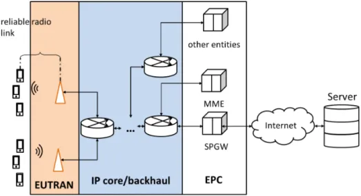
The architecture of the LTE core network is the ground true network we are making our abstract and assumptions on. Its architecture is shown in Fig.3.1. The architecture of 5G RAN and Non standalone 5G has the exact same backbone as LTE. As we can see that the network is composed of Evolved Universal Terrestrial Radio Access Network (EUTRAN) and the EPC.
Fig. 3.1 LTE interface stacks
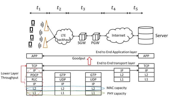
The stack used among the whole LTE network is shown in Fig.3.1. It is a heterogeneous network with a wired backhaul network with user and control plane and a Radio access network. LTE treats the Upper layer TCP/IP packets as the ’Application’ layer data. Firstly we simply revisit the data bearer structure in mobile backbone network.
3.2.1
LTE backhaul
The connection between a mobile network and the outside internet is Service and Packet delivery network gateway (SPGW). It is the entrance of mobile network and manages the traffic in the mobile backhaul(wired backbone network). It encapsulates the TCP/IP packet into the ’Bearer’.
The BLUE protocol stack in Fig. 3.1is used by Control plane, where the signalling of mobile network operators flows through including authentication, billing, policy control, etc.. The RED protocol stack is specifically used by the user plane. The data from a remote server
will be delivered to eNB by this family of the protocol. The communication between eNB and the EPC entities, in both control plane and user plane, are mostly delivered in a wired manner. For a different type of packet, the bearer uses a different combination of the protocols to accomplish the packet delivery. For the user plane, the bearer uses GTP-U, which generally running over UDP, to carry the traffic from UEs. Since GTP protocol has no retransmission or feedback mechanism, the end to end data transfer from UE to the SPGW is unreliable. The design of the backhaul fits the original purpose of the TCP well since congestion can also exist in the LTE core and backhaul network. It seems reasonable that the congestion control mechanism in TCP server can also manage the congestion in the LTE backhaul. However, there may be up to tens of hops of routing/switching between EUTRAN and EPC entities. The delay in the backhaul network may also be considerable. The upper bound of the non-really time U-plane data is up to 300ms [7]. The signalling in the LTE system, on the other hand, uses SCTP protocol which is a reliable transport layer protocol. To guarantee the QoS in an LTE core/backhaul network, QoS Class Identifier(QCI) has tagged to each, bearer. Generally, the control signal exchange has higher priority, and when the congestion arrives at the specific nodes in the LTE network, the buffered data with lower priority will be discarded first. However, in the existing network, QCI and the dedicated option is generally disabled. Basically, all the traffic, except VoLTE service, are running on the default bearer. Since the control traffic is negligible in the LTE xhaul(backhaul/fronthaul), the data packets are delivered in a similar best effort manner on the internet.
Such design of using TCP/IP to bear traffic can be dangerous since the loss-based congestion control will cause the bufferbloat mentioned above effect. The ETSI is considering changing such architecture[5].
In this research, the simplified model, as in Fig.3.4is assumed. In the following sections and chapters, our discussion on the mobile network is based on this illustration. Our assumption is the CCA we designed is working in the PGW where all the traffic from outside internet (remote server or local CDN) is treated as the saturated application layer input. Hence with the filtering of SPGWs, a network with only pure novel CCA in the mobile backbone is formed where the network operator has full control of the performance of traffic.
3.2.2
LTE Radio Access Network
A mobile Radio access network is a network utilise the wireless channel with centralised scheduling manner. In such system, radio link spectrum resource, spatial reuse feature, code (for code division multiple access) and time slots (for time division multiple access) [8] are the managed by the infrastructures running mobile network standards.
The reason why mobile Radio Access Network (RAN) must be so complex is: radio link without appropriate PHY technique and MAC design is not as reliable as a wired channel. It can be lossy, and the BER is high[9,10]. The appropriate Radio link technique is critical for the wireless channel to have robust performance. With developing an understanding of radio PHY characteristics, two mainstream wireless technique exists:
1. Carrier Sense Multiple Access with Collision Avoidance (CSMA/CA)[11] based dis-tributed resource random access. The typical PHY/MAC branch is the 802.11 family Wi-Fi technique [12]. The traffic management in such type of network can be fuzzy[13–
15]
2. Mobile/Cellular network with a centralised base station scheduling mechanism[16]. The traffic management has more dynamics compared to distributed traffic competition manner in Wi-Fi [17–19].
Though Wi-Fi and mobile cellular network have a different manner of sharing or scheduling the resource in a time-varying wireless channel, they do have some common fundamental elements which affect congestion states in the network:
• More and more advanced Radio Link technique to improve the robustness and wireless resource utilisation
• Larger buffer size compared to the decades ago, thanks to the lower cost of hardware The mobile cellular network(mobile network, in short) is our research focus. To have a well-performing system, not only the RAN and simply larger buffer are taken into consideration but also the various hardware and software are carefully combined together. We are going to introduce the fundamentals of mobile network system from the perspective of the Radio Link technique and buffer in the following subsection.
Radio Link Capacity
The development of mobile network on radio link use the following line of thought to makes a tradeoff between the lossy nature and the
1. Increase the unit time resource utilisation with more and more advanced PHY layer with more and more advanced Modulation and coding schemes (MCS) and massive Multiple-Input Multiple-Output(MIMO) technique
2. Reduce the interference by using beamforming thanks to the multi-antenna[20] and by using the dynamic MCS of central scheduling manner of the base station to select the most efficient MCS which guarantees robustness.
3. Reduce the loss by trading the detected packet loss with processing time or retransmission by applying error correction coding and ARQ/HARQ mechanism.
All these features are made possible thanks to the advancing processing and storage power, research inputs and engineering efforts. These features are implemented in different layers of RAN. It will be introduced latter.
As mentioned in Chapter1, in the GSM and EDGE[1] of 2G network architecture, the PHY capacity varies in tens of KBps level. RTT from the Remote Server(RS) to the User Equipment(UE) is usually above the one second and some times even more than 10-second [21,
22]. With the development of 3G/4G mobile network, the PHY capacity grows significantly(up to tens of MBps in 3G and hundreds of MBps in 4G), while the per-user buffer size is extended to MB level(1+MB/4+MB in HSPA/HSPA+, 5MB+ in LTE[23]). The variation of the radio link capacity is shown in Fig3.2.
The other typical difference among 2G, 3G, 4G [22–29] networks is listed in the table below: Note that the capacity in Table3.1is the PHY capacity.
RTT Transition Time interval Buffer(Per user) Typical Capacity(DL) 2G[1,30] >1s >138ms ≈1MB 9.05-21.4Kbps(GPRS), 9.2-59.6Kbps(EDGE) 3G[28,31,32] ≈100-200ms 10-80ms(UMTS), 2ms(HSDPA) ≈4MB 0.9-14.4Mbps (WCDMA) 4G[32–34] ≈70ms 1ms ≈5MB 0.9-345.6Mbps(LTE)
Table 3.1 Difference among 2G 3G and 4G mobile radio link(typical values)
The layered throughput, which can be measured from Media Access Control(MAC), Radio Link Control(RLC), all the way through Packet Data Convergence Protocol (PDCP), presented to the transport layer is much lower than this peak PHY value due to the presence of lossy wireless nature, the resulting HARQ and other error correction technique. This is to be discussed later in this chapter. To catch the trend of the advanced mobile design, and the buffer feature of backbone network we review the full LTE mobile network architecture in the following sections.
Buffer size and bufferbloat
Due to the variation of Radio link capacity, a node in the network is treated as a bottleneck once its capacity cannot digest the incoming traffic. Bufferbloat is a phenomenon caused by the network device with a deep buffer while the BW is not high enough. Namely the length of queue inflated to a level where the packets in it is experiencing a high delay before loss.
Naturally, an appropriate amount of buffer is necessary to reduce the loss in the network. This makes a network node to become a queuing system. In such a system, pursue the queue length can be a harmful strategy in the perspective of the round trip time for time-sensitive application or a Data-Acknowledgement loop. According to the type of network and the traffic expectation, Queuing theory[35] can suggest an optimal queue length. However, the total buffer size is relatively large[36] and a typical buffer depth in LTE network is between 2MB to 6MB[26]. The mainstream AIMD loss-based congestion control is greedy enough to always inflate the queue in the network. Until a loss timeout timer expired, a loss-based congestion control mechanism will keep on increasing its CWND in Additive increase or even more aggressive manner.
The interesting fact is that in the cross-layer tracing study[30], the error losses are not detected due to the reliable link layer protocol exists in GPRS radio link protocol stack. Though typical buffer size is small(measured as up to 50KB/30KB in DL/UL per user[30]), the low capacity tends to drain the buffer slowly. Hence the bufferbloat problem exists in the GPRS network as a result of buffering nature of the mobile network[30]. These data show that the bufferbloat will exist as long as the buffer size and the capacity of radio link do not match.
Last but not least, with the increased peak radio capacity and buffer size, some rethinks should also be made on the judgement of radio link is the bottleneck in the network. For example, the router in the mobile backhaul/Internet/EPC may introduce higher delay than the radio access network if it locates in a busy crossway. Hence the design of CCA in a mobile network for edge data transmission should take the radio link and wired bottleneck into consideration. In the following section, we will look into the full architecture of LTE mobile network.
Radio Access Network Protocol stack
In this thesis, we firstly focus on the radio access network(RAN) bottleneck. Hence the starting point is to utilise the information invoked from PHY, MAC or RLC layer. The layered technical detail is reviewed to find out the information we need to implement such information.
The wireless link was described as lossy and poisoned the TCP connection quality in the way of high Packet Error rate[10]. Decades latter, with the development of the Coding techniques, the dynamic scheduling schemes, e.g. dynamic MCS, and cross-layer ARQ the link failure rate exposed to the upper layer is lower than 10−6[7] in LTE network.
An abstract of the architecture of the user plane of LTE network is shown in the Fig.3.3. On the radio link side, the LTE RAN consists of PDCP, RLC, MAC and wireless PHY layers. PDCP, RLC and MAC layers have their duty on QoS:
• PDCP layer compresses the IP data and manages their order with PDCP sequence num-ber(SN). It ensures the intra-LTE handover is seamless, and the packets are delivered in
Fig. 3.3 Brief LTE protocol stack
order up to the higher layer. When the handover of a user between cells happens, the data in the specific UE buffer is transmitted from one eNB to another. A temporary increase of RTT may be experienced at handover event. However, the reliable delivery at handover and PDCP status report may not always implement. As a result, the retransmission and the lossless handover may not always be the case in the LTE network. LTE private buffer space for each mobile user equipment (UEs). Hence to keep the number minimum number of the in-flight packet can help avoid catastrophic loss during handover and further achieve better link utilisation.
• RLC layer consists of three modes: Transparent Mode (TM), Unacknowledged Mode (UM), and Acknowledged Mode (AM). AM mode provides most functions including resegmentation, reordering, duplication discard, etc., while TM mode buffers the upper layer data a bit. Since there can be an error in MAC layer, the erroneous data packet can lead to MAC layer retransmission and further cause disorder delivery for upper layer while the incorrect ACK/NACK can cause retransmission from RLC layer.
• MAC layer will request data from the RLC layer buffer when the resource allocation scheduling negotiation is finished. The eNB manages both uplink and downlink schedul-ing. UE will report the Channel status to eNB in a control channel, and the scheduling algorithm in eNB MAC layer will decide according to several constraints including the reported channel quality, the number of users, and the size of data. The scheduler further determines the scheduling for the next time slot, and distribute the results back to the UE by Downlink/Uplink Control Information (DCI/UCI).
In this work, the characteristic of LTE-RAN above are studied in the purpose of transplanting, for the first stage, the 3G-QUIC based CQIC algorithm into LTE UE. Further, the study is used to design the first prototype of CDBE and CDBEv2 in Chapter6and7.
Fig. 3.4 Simplified LTE Network architecture with RAN, backhaul and gateway
3.3
End-to-End Congestion control methods for Quality of
Service
Work in [37] classified TCP improvement on the last-hop wireless network into four categories: 1. split connection
2. end-to-end connection 3. explicit connection
4. localization of wireless loss
With the development of the mobile network technique, some function of subcategories men-tioned in the article is entirely fulfilled by the existing mobile network infrastructures, e.g. ARQ/HARQ in eNB These techniques address the wireless loss at the cost of time domain efficiency or processing powers. Hence the delay in radio uplink or downlink can vary in a wide range. In our research a new category scheme is applied to the development of the mobile infrastructure.
Based on the different network position where the solutions should be applied, existing designs for the QoS improvement on the mobile network can be classified into two categories: end-to-end(e2e) and the middlebox. The definition of the middlebox here is generalised. It can stand for any devices in the network between the two endpoints of the service including eNB, S/PGW and multifunction router. The location of middleboxes may affect the tradeoff between the cost of deployment and effectiveness.
Most TCP solutions can further be subcategorised by with or without the support of cross-layer features. The other cross-cross-layer protocol needs to implement both server and a massive amount of clients, even if the improvement is remarkable, their usage may be limited. Again the deployment problem is through severe but out of the discussion of this report. Other solutions may include the suggestion of upgrade the RLC status[38] , A brief comparison among different categories will be concluded, and we are going through the detail of them in the following subsections.
Fig. 3.5 Categories of congestion control solutions
3.3.1
Non-Cross-Layer protocols
End-to-End
The main end-to-end congestion control algorithms review and analyzed in this thesis are listed below:
1. loss-based CCA. There are plenty of variations in this category of CCA. Loss-based CCA can take over the full depth of the buffer in the network. In a network with shallow buffer, such design can get frequent loss and low bandwidth utilisation. In a network
with a deep buffer, such architecture can result in a queue heap up of BIF and the when an RTO happens a large number of packets will be retransmitted. Hence the bandwidth utilisation is also low from the perspective of goodput.
2. There is another category of CCA, named delay-based CCA. This kind of CCA uses the delay as an indicator of congestion and further alter the CWND to control the traffic. The low-delay and fairly decent goodput can be achieved when the RTT status is relatively stable. Note that the delay-based CCA can lose its share of buffer and pipeline occupation. 3. The latest TCP version combines the bottleneck bandwidth and round trip delay (BBR)[39] proposed by Google. This algorithm possesses a new state machine to utilise the band-width estimation(BE) and RTT. This CCA is widely deployed in Google’s network. Its behaviours in the mobile network have not been tested yet. Hence it is interesting to try the algorithm in this thesis.
4. In one of the Google proposal, called “CQIC”[40], the customer terminal can try to predict the radio allocation and transmit this information to the TCP source. TCP source rate adaptation is then possible, similarly to the previous proposal.
Thought not pointed out explicitly, the most important features of a congestion control algorithms are:
1. probe for more bandwidth and, 2. balance share of bottleneck.
To achieve the goal mentioned above, a congestion control algorithm must not only rely on the lower layer capability report but implement an engine function on the transport layer as a guarantee of end-to-end service. Major Non-Cross-Layer E2E solutions fall in the TCP domain, and the way to achieve the goal is to use a feedback signalling control loop[41]. The abstract and the modelled analysis is shown in the next Chapter4. Now we discuss the typical engineering features of the feedback loop.
The two mainstream transport layer protocols are User Datagram Protocol (UDP)[42] and Transport Control Protocol (TCP)[43] and the latter is used in mobile network transport layer for congestion control. Different from the unreliable transmission provided by UDP, the connection-oriented TCP uses feedback packets named Acknowledgements (ACK) to provide reliable end-to-end data delivery. Moreover, these ACKs are opportunistically used to detect network congestion, through congestion control algorithms (CCA); These algorithms offer different throughput-RTT tradeoff and are to be used in different scenarios, including but not limited to the type of application and the feature of the network.
For reliable transmission, a positive acknowledgement (ACK) is employed. The receiver of the data packet will send ACK if the packet is received successfully. Furthermore, the buffer state of the receiver will also be embedded in the ACK as Flow Control (FC) indicator. With the help of this feedback signalling and the information within, the server can regulate the transmission rate using Sliding Window (SW ) mechanism with the FC information, named receiver window (RWND) size on the server. The other constraint of the SW mechanism is the CCAs.
Generally, a transport layer manages the end-to-end traffic in a IP network nowadays[44]. A transport layer also exists in a mobile PDN for both control plane and user plane since the data exchange in a mobile network also use the layered TCP/IP packet delivery architecture.
The congestion window (CWND) is their cornerstone, as it controls the unacknowledged data volume in transit (Bytes In Fly, BIF) between the TCP source and destination.
In the 4G network, the typical Round Trip Time(RTT) is much lower than that in 3G[32], and it can be expected that delay in a mobile network shall further be reduced to 10ms level[34]. However, the wireless resource scheduling, mobility and buffering instability in the network make the RTT tricky evidence of packet loss. Hence the accurate RTT based TCP vegas[45] will not an appropriate solution for RTT varying wireless network since it is per ACK based CWND modification manner and the reaction to BW variation can be too slow.
The conventional Congestion control algorithm(CCA) in consists of Slow Start(SS), Con-gestion Avoidance(CA), Fast Retransmission(FReTx), Fast Recovery(FRecv) and Timeout Retransmission. SS increases the transmission window(a.k.a. congestion window, CWND) size exponentially per ACK before the CWND reaches Slow Start Threshold(ssthresh). Once the CWND is equivalent or larger than ssthresh, TCP server stops SS and is engaged to Congestion Avoidance. In CA, once the packet loss is confirmed (generally Retransmission Timeout, RTO), TCP server will set ssthresh as half the current CWND size and retreat to SS. If the third duplicated ACK reaches before RTO. However, the FRTx starts before the RTO. This is the features of most conservative old version TCP Tahoe implemented as suggested by [46]. TCP Reno [47][48] triggers FRecv, instead of FRTx, which does not force TCP Server to go back to SS by just half the CWND. The legacy TCP considers network congestion results in all the losses.
By replacing the conventional CCA growth logic in CA state with the CUBIC function, the TCP CUBIC[49] is one of the most widely deployed TCP variants since it is by default built-in Linux kernels from version 2.6.19.
All these kind of the aforementioned Loss-Based CCAs have a slow start state. A slow start is to discover the current bandwidth by filling the buffers in the network. Once the congestion loss point is discovered, the ssthresh is the operating baseline defined in equation as twice
Fig. 3.6 Illustrate the basic concept behind loss-based congestion control
the Bandwidth Delay Product(BDP). To avoid frequent loss, the loss-based method ’carefully’ operate in the buffer-filling operation area, which is between the full pipeline and the full buffer queue lengths. Once the bottleneck bandwidth(BWBtlnck) is increased for any reason, the Reno
style congestion avoidance manner may take a very long time to catch the newly available bandwidth. Hence BIC[50] introduces the faster recovery and probe. The basic idea is to be more cautiously near the recorded losing point and be more aggressive when far away from
the losing point whether it is in actual probe stage or congestion avoidance. To avoid the RTT sensitivity caused by the ACK-driven binary search method, TCP Cubic [49] is introduced to use the following cubic function to smooth the procedure:
W(t) = C(t − K)3+Wmax K= 3 r Wmaxβ C (3.1)
where provides the configurable parameters C and β . C controls the speed of converge, and β controls the friendliness to TCP.
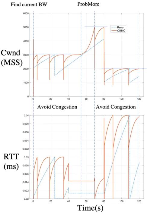
To compare the performance of CUBIC and Reno, we simulate a fixed network in NS3 simulator, where Maximum BIF of the network varies from 3000pkts to 5000pkts at t=50s and decreases to 2000pkts at t=80s. The result is simply shown in Fig.3.6. It shows that CUBIC has faster converge when a loss happens and has more aggressive bandwidth probe manner. Concerning the Throughput, CUBIC has a better performance. However, higher throughput is not necessarily resulting in higher Goodput. The RTT performance of CUBIC is also worse than that of Reno.
To be more polite and mitigate the potential extra delay, the delay-based CCA like Tcp vegas[45] is used to maintain the buffer on a lower level:
expectedt+1=CW ND t RT Tmin actualt+1= CW ND t RT Tmeasured Di f f = expectedt+1− actualt+1 CW NDdi f f = Di f f ∗ RT Tmin (3.2)
By calculating the difference between expected capacity and actual capacity of the round, if the upper-bound(α) or a lower-bound(β ) is exceeded, the algorithm will be increased or decreased respectively:
Algorithm 3.1:Vegas congestion avoidance logic 1 if CW NDdi f f <= α then
// There is still room, send more 2 cwnd= cwnd + 1;
3 if CW NDdi f f > β then
// congestion happens, take a backoff 4 cwnd= cwnd − 1;
Delay-based congestion control algorithms can maintain the queue depth to a relatively low level. However, the space for this kind of algorithm will be compressed by the loss based algorithm since the nature delay-based CCA is to reduce the CWND when RTT increase is made by the loss-based congestion control algorithms[51,52]. Similarly, the rerouting[53] can also cause a similar effect.
TCP-Jersey[54], TCP New Jersey[55] and TCP NJ+[56], estimates the available bandwidth using more accurate algorithms according to the ACK arriving time. The ssthresh is also adapted according to the estimation. The Congestion warning mechanism using the ECN bits is also implemented in the Jersey family of TCP and conveys the simple image of the bottlenecked queue to the sender. The JTCP[57] and uses the jitter ratio to predict the reason for packet loss and adapt to the congestion control strategy. They employed the one-way delay jitter in RTP[58] and Jitter Ratio in [59] to compare with the threshold to distinguish the network congestion or wireless link loss. However, these widely used/experimented variances of TCP cannot fully utilise the available wireless resources nowadays.
Based on the hypothesis that the wireless link is lossy, and the BER is high[9,10], TCP West-wood is proposed[60]. It monitors the returning ACKs and estimates the available bandwidth accordingly.
TCP Veno[61], similar to Westwood, estimate the state of the connection while AIMD scheme of Reno is also applied. The SS triggered by RTO will have adaptive ssthresh according to the congestion status. It keeps on measuring the minimum RTT and update the bandwidth estimation:
BW E= Packed/RT T (3.3)
Once a triple duplicated ACK event or a retransmission timeout happens, the ssthresh and the CWND are reset following the Algorithm3.2. Such a manner not only reveal the expected operation starting point but also allows the sender to stick to it. The tradeoff is to
Algorithm 3.2:DupAck in Westwood 1 ssthresh=BW E∗RT TPktSizemin ;
2 if cwnd > ssthresh then 3 cwnd= ssthresh
However, as described earlier, the lossy nature of wireless link in the mobile network has been managed by the HARQ/ARQ mechanisms in mobile MAC and RLC layers [2].
The utilisation of the available bandwidth is less than 50% for TCP connections[26] and Westwood, Veno, and Cubic does not significantly outperform Reno[23]. This is predictable since these variance estimates the Congestion and Bandwidth on per ACK level. Such estimation
Algorithm 3.3:RTO in Westwood 1 ssthres=BW E∗RT TPktSizemin ;
2 cwnd= 1 ;
3 if ssthresh < 2 then 4 ssthresh= 2
will always be inaccurate due to the fast-changing nature of the Mobile network as adaptive MCS and resource allocation is applied, even though the UE is static.
LEDBAT [62] is one of the Non-TCP and non-cross-layer e2e solutions. It has faster con-gestion reaction than TCP thanks to the one-way delay estimation. It also uses a less aggressive manner to utilise the background resource to improve the overall bandwidth utilisation.
These are the popular conventional CCAs which are widely tested or deployed in the existing networks. Not only tested in the fixed network but also in a mobile network. The design logic of loss-based CCA treats the buffer as an extra resource which should also be shared by the co-existing flows.
However, from my point of view, the buffer is a redundancy and flexibility for the flows to temporally invoke while allocating the bandwidth, rather than a must-use resource to fill with greedy manner.
Middle box design
There are several important studies on split-connection protocol designs. The more accurate name should be TCP proxy technique. The middlebox receives the packets from the TCP sender and reacts according to their consciousness of the UE status. This procedure may introduce buffering, processing of the data packet and forward of the ACK packet. The end-to-end TCP connection manner may not be maintained. Indirect TCP(I-TCP) in[63,64] is the initiator of split TCP concept with complete design and implementation. There was no 3G/4G network back to 1995, and the designer employs Mobility Support Router (MSR) to separate the connection between the TCP servers and clients as Fig.3.7shows. The original end to end semantic is split into a regular TCP connection between MSR and RS and one modified wireless TCP connection between UE and the MSR. The protocol takes care mobile handover by re-establishing socket for the same pair of endpoints on newly connected MSR and transfer the corresponding buffered data in old MSR to the new MSR. The handover latency is high(1430 micro seconds for buffers depth of 32Kbtes) since the technique is limited to the computer constraint back then. Similar designs are MTCP[65] and METP [66] with different wireless link Optimisation as in Fig.3.8. MTCP optimise the wireless last hop on socket level
![Fig. 7.2 How does β change with RTT on interval RT T min ∈ [20ms, 300ms]](https://thumb-eu.123doks.com/thumbv2/123doknet/14527484.723115/128.892.205.659.525.888/fig-does-β-change-rtt-interval-rt-min.webp)
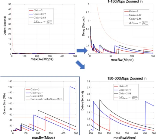
![Fig. 7.5 The the mean, maximum, minimum delay and lost percentage caused by different pairs of G pacing and BW (t 0 ) for BW Btlnck ∈ [1Mbps, 150Mbps]](https://thumb-eu.123doks.com/thumbv2/123doknet/14527484.723115/134.892.185.698.177.644/maximum-minimum-delay-percentage-caused-different-pacing-btlnck.webp)