Djilali Liables University of Sidi Bel Abbes Faculty of Technology
Department of Mechanical Engineering
Thesis
Presented by :
BENAYAD ZOUAOUI
TO GET THE PHD DEGREE
Domain: Science and Technology
Field: Mechanical Engineering
Specialty: Energy and environment
Entitled:
Before the jury composed of:
Pr. MAKHLOUF Mohammed U.D.L. SBA President of the jury
Dr. LAOUEDJ Samir U.D.L. SBA supervisor
Pr. JUAN PEDRO SOLANO U.P.C. SPAIN Co-superviser
Dr. MEDBER Mohamed Amin U. MASCARA Examiner
Dr. BENAMARA Nabil U.D.L. SBA Examiner
Numerical Investigation of Cooling Electronics
Components
Acknowledgments
I would like to express my deep gratitude to Prof LAOUEDJ Samir
as he has always been with me, all along my work, bestowing advice upon me
and always showing his availability.
I am highly indebted with special Thanks to the members who
concerned themselves with reading, correcting and evaluating my thesis:
Pr.
MAKHLOUF Mohamed, Dr. MEDBER Mohamed Amin and Dr.
BENAMARA Nabil. I would like to pay tribute to them here, as I can hardly
find adequate words of thanks.
I am equally indebted to Professor JUAN Pedro Solano,
the Engineering
Department of Thermal and Fluids, Polytechnic University of Cartagena,
Murcia, Spain as well as well the team at the Laboratory of Renewable Energies
Mr. Alberto Egea Villarreal and Mr. Antonio Zamora. Helping with precious
documentation, providing insightful advice, valuable suggestions and moral
support which, I must confess, gave me a giddy round of pleasures beyond all
the stress and constraints.
Dedications
Every challenging work needs self-efforts as well as guidance of elders
especially those who were very close to our hearts My humble effort is dedicated
to: The sake of Allah, my creator and my master My great teacher and
messenger, Mohammed (May Allah bless and grant him), who taught us the
purpose of life.
My undying gratefulness goes to my two shields and mentors in life my
dear parents who proved to be the perfect example of the desired parents. I
fancy granting my thankfulness to my grandparents, dear brother and sisters for
their support and love.
My eternal gratitude goes to my colleagues and friends Mr. DAHMANI
Abderraouf and Miss MECIEB Fatima zohra and Miss. BENSAAD Siham, for
everything he helped with for the sake of fulfilling this work. To all those whom
my memory failed to recall, many thanks for every momentous or trivial thing
you have taught me for it was all helpful.
Abstract
Recently, the cooling process for electronics components has attracted many researchers and several techniques for improving the cooling efficiency and heat transfer rate have been demonstrated. One of the best efficient techniques is the introduction of a synthetic jet and the modification of heating surface. In the present study, the form of heating surface, as well as the shape and number of orifices and the signal of the diaphragm has been modified to improve the synthetic jet. These modifications are novel and have been applied for the first time with very good thermal enhancement efficiency for microchannels with synthetic jets applications. This study allowed us to make a quantitative comparison between a basic case with a periodic signal and modified case.
The unsteady flow and heat transfer for the two-dimensional synthetic jet are solved using ANSYS fluent code and k-ω (SST) model is selected to account for fluid turbulence.
Obtained results showed a cooling improvement of about 60% for the modified case with two synthetic jets inclined with 3° and converged form of orifices and 10 µm of undulation heated wall when changing the position of the cavities so as to introduce a bi-periodic signalcompared with the basic case.
Key words: Synthetic jet; (SST) K-ω turbulence model; Undulation heated wall; Nusselt
صخلم
ا يف
ةنولآ
،ةريخلأا
نم ديدعلا ةينورتكللإا تانوكملا ديربت ةيلمع تبذتجا
،نيثحابلا
ضرع مت دقو
ةرارحلا لقن لدعمو ديربتلا ةءافك نيسحتل تاينقتلا نم ديدعلا
.
ليدعتو ةيعانطصا ةثافن لاخدإ يه ةيلاعف تاينقتلا رثكأ نم ةدحاو
لا
لا حطس
نخاس
.
ةساردلا يف
،ةيلاحلا
لكش ليدعت مت
لا
س
حط
لا
نخاس
لل
ةينورتكللإا تانوكم
عم
ليدعت
تاحتف ددع
جورخ
دربملا
و
لكش كلذك
ةيعانطصلاا ةثافنلا نيسحتل زجاحلا باجحلا ةراشإ
.
اهقيبطت مت دقو ةديدج تلايدعتلا هذه
ةرم لولأ
مت و
ىلع لوصحلا
اًدج ةديج يرارح نيسحت ةءافك
ل ةبسنلاب
تاذ ةريغصلا تاونقل
لاا ةثافنلا تاقيبطتلا
ةيعانطص
.
ةيساسأ ةلاح نيب ةيمك ةنراقم ءارجإب ةساردلا هذه انل تحمس
ةلدعم تلااحو ةيرود ةراشإب
.
ةرارحلا لقنو رقتسملا ريغ قفدتلا لح متي
ل
ةثافنل
مادختساب داعبلأا ةيئانث ةيعانطصلاا
جمانرب
fluent
ANSYS
جذومن رايتخا متيو
K-ω (SST)
لئاوسلا بارطضا باسحل
.
اتنلا ترهظأ
يف ةدايز اهيلع لوصحلا مت يتلا جئ
مقر
لا
وحنب تلسن
%
06
عم ةلدعملا ةلاحلل
ثافن
نيت
نيتلئام نيتيعانطصا
دا
ت
ف
ت
ح
ا
ت
ب
ان
س
دا
د
م
تق
ا
ر
ب
و
ب
ردحنم
3
ةجرد
و
06
جومت نم رتموركيم
رييغت دنع نخاسلا رادجلا
فيواجتلا عضوم
و
ةفاضا
تارتفلا ةيئانث ةراشإ
ةنراقم
ةيساسلأا ةلاحلاب
.
ةيحاتفم تاملك
:
ةثافن
ةيعانطصا
بارطضلاا جذومن ؛
K-ω (SST)
جومم نخاس رادج ؛
؛
مقر
تلسن
؛
ةيرود ةراشإ
؛
ةراشإ
تارتفلا ةيئانث
.
RESUME
Récemment, le processus de refroidissement des composants électroniques a attiré de nombreux chercheurs et plusieurs techniques permettant d'améliorer l'efficacité du refroidissement et le taux de transfert de chaleur ont été démontrées.
L'une des techniques les plus efficaces est l'introduction d'un jet synthétique et la modification de la surface chauffante. Dans la présente étude, la forme de la surface chauffante ainsi la forme et le nombre d'orifices et le signal du diaphragme ont été modifiés pour améliorer le jet synthétique. Ces modifications sont nouvelles et ont été appliquées pour la première fois avec une très bonne efficacité d'amélioration thermique pour les micro-canaux avec des applications de jets synthétiques. Cette étude nous a permis de faire une comparaison quantitative entre un cas de base avec un signal périodique et des cas modifiés.
L'écoulement instable et le transfert de chaleur pour le jet synthétique bidimensionnel sont résolus à l'aide du code fluide ANSYS et le modèle k-ω (SST) est sélectionné pour tenir compte de la turbulence des fluides.
Les résultats obtenus ont montré une amélioration de refroidissement d'environ 60 % pour le cas modifié avec deux jets synthétiques inclinés avec 3° et forme convergente des orifices et 10 µm d'ondulation de la paroi chauffée quand on change la position des cavités ainsi introduire un signal bi-périodique par rapport au cas de base.
Mot clé :Jet synthétique ; modèle de turbulence K-ω (SST); paroi chauffée ondulée ; nombre de Nusselt ; signal périodique ; signal bi-périodique.
convective exchange surface………... 5
Figure 1.2. Forced air cooling system Radiator………. 6
Figure 1.3. Micro-channel liquid cooling (EnermaxLiqmax 120S)………... 7
Figure 1.4. Mini-channel liquid cooling………. 7
Figure 1.5. Cold plate liquid cooling……….. 7
Figure 1.6. Spray cooling principle……… 8
Figure 1.7. Jet cooling……… 9
Figure 1.8. Use of PCM with graphite for cooling batteries………. 10
Figure 1.9. Dielectric fluid cooling systems with external (a) internal capacitor (b)………. 11
Figure 1.10. Schematic diagram of a heat pipe……… 11
Figure 1.11. Schematic diagram of a thermosiphon in a closed tube………... 12
Figure 1.12. Two-phase loops LHP and CPL……….. 14
Figure 1.13. Peltier Effect………. 16
Figure 1.14. Shematic of a synthetic jet actuator……….. 17
Figure 1.15. Characteristics parameters effecting the flow field of Synthetic Jet…… 18
Figure 2.1. Discretization in finite volumes in the monodimensional case……… 39
Figure 2.2. Discretization in finite volumes in the bidimensional case………….. 40
Figure 2.3. Bidimensional description of a finite volume……….. 41
Figure 3.1. Basic case with synthetic jet cross a micro-channel……… 51
Figure 3.2. Comparison of the present results with those of Chandratilleke et al. [82] for the variation of the Local Nusselt number versus normalized distance for Vi =1 m/s……….. 53
Figure 3.3. Representation of boundary conditions 1………. 53
Figure 3.4. Computational grid 1……… 54
Figure 3.5. Comparison of Nusselt number for the heated surface between Basic case and Modified case at different undulation heated wall 10, 12.5, 20 µm, and A = 75 µm while the inlet velocity Vi = 1 m/s………. 54
Figure 3.6. Nusselt number on the heated surface for different amplitudes, (a) Basic case, (b) Modified case with undulation heated wall of 10 µm………….…… 55
50 and 75 µm, for Vi=1 m/s………...……….. 56
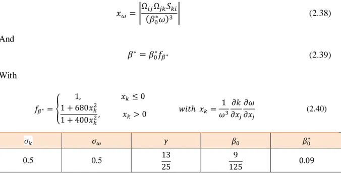
Figure 3.8. Contour plots of the static Temperature after one cycle for Vi = 1 m/s and A = 75 µm, (a) Basic case, (b) Modified case with undulation heated wall of 10
µm……… 56
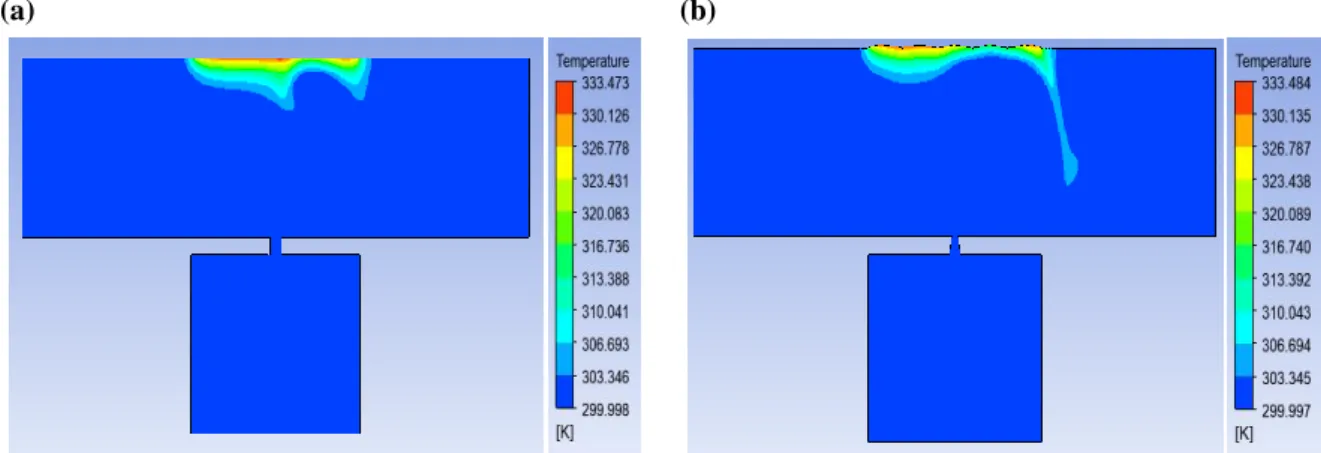
Figure 3.9. Contour plots of the magnitude velocity for four cases [(a) t=T/2 and (b) t=T for the Basic case, (c) t=T/2 and (d) t=T for the Modified case with 10 µm of undulation heated wall, (e) t=T/2 and (f) t=T for Modified case with 12,5 µm of undulation heated wall, (g) t=T/2 and (h) t=T for the Modified case with 25 µm of
undulation heated wall]; for Vi = 1 m/s ; A = 75 µm……… 57
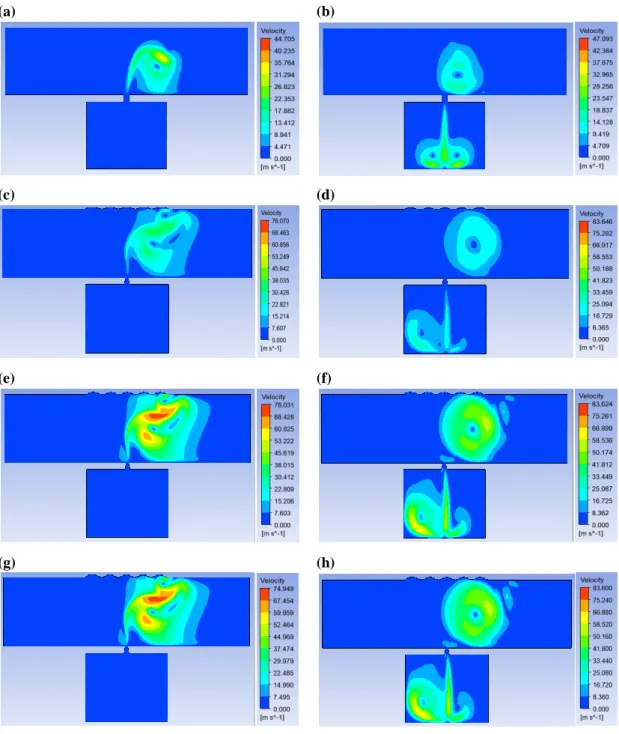
Figure 3.10. Contour plots of the magnitude velocity for one cycle, (a) Basic
cases, (b) Modified case with undulation heated wall of 10 µm; for Vi = 1 m/s; A =
75 µm………...……… 58
Figure 3.11. Representation of boundary conditions 2………. 59
Figure 3.12. Computational grid 2……… 59
Figure 3.13. Nusselt number on the heated surface for different amplitudes, (a)
Basic case, (b) Modified case with two cavities………. 60
Figure 3.14. Average Nusselt Number for Basic case and Modified case with two
cavities at different undulation heated wall 10, 12.5, 20 µm, for the three
amplitudes A= 25, 50 and 75 µm, for Vi = 1 m/s ………... 61
Figure 3.15. Contour plots of the magnitude velocity after one cycle
for Vi = 1 m/s and A = 75 µm, (a) Basic case, (b) Modified case with two cavities… 61
Figure 3.16. Contour plots of the static Temperature after one cycle
for Vi = 1 m/s and A = 75 µm, (a) Basic case, (b) Modified case with two cavities… 62
Figure 3.17. Contour plots of the magnitude velocity for one cycle,
for Vi = 1 m/s and A = 75 µm, (a) Basic case, (b) Modified case with two cavities… 63
Figure 3.18. Boundary condition 3………... 64
Figure 3.19. Structured quadratic mesh considered 3……….. 64
Figure 3.20. Nusselt number on the heated surface for different amplitudes, (a)
Basic case, (b) Modified case with two cavities inclined………... 65
Figure 3.21. Average Nusselt Number for Basic case and Modified case with two
inclined………. 66
Figure 3.23. Contour plots of the static Temperature after one cycle
for Vi = 1 m/s and A = 75 µm, (a) Basic case, (b) Modified case with two cavities
inclined………. 67
Figure 3.24. Contour plots of the magnitude velocity for one cycle, for Vi = 1 m/s
and A = 75 µm, (a) Basic case, (b) Modified case with two cavities inclined….. 68
Figure 3.25. Nusselt number on the heated surface for (a) Basic case, (b)
Different Modified cases for Vi = 1 m/s and A = 75 µm……….………. 69
Figure 3.26. Average Nusselt Number for Basic case and Different Modified
cases, for the three amplitudes A = 25, 50 and 75 µm, for Vi = 1 m/s………. 70
Figure 4.1. Boundary condition 4………... 73
Figure 4.2. Structured quadratic mesh considered 4……….. 73
Figure 4.3. Nusselt number on the heated surface for different amplitudes, (a)
Basic case with periodic signal, (b) Modified case with bi-periodic signal………… 74
Figure 4.4. Comparison of Nusselt number for the heated surface between basic case with periodic signal and modified case with bi-periodic signal at Vi = 1 m/s; A
= 75 µm……… 75
Figure 4.5. Average Nusselt Number for basic case with periodic signal and
modified case with bi-periodic signal……….. 75
Figure 4.6. Contour plots of the magnitude velocity after one cycle for Vi = 1 m/s and A = 75 µm, (a) Basic case with periodic signal, (b) Modified case with
bi-periodic signal……….. 76
Figure 4.7. Contour plots of the static Temperature after one cycle for Vi = 1 m/s and A = 75 µm, (a) Basic case with periodic signal, (b) Modified case with
bi-periodic signal……….. 76
Figure 4.8. Contour plots of the magnitude velocity for one cycle for Vi = 1 m/s and A = 75 µm, (a) Basic case with periodic signal, (b) Modified case with
bi-periodic signal……….. 77
Figure 4.9. Boundary condition 5………... 78
Figure 4.12. Average Nusselt Number for basic case with periodic signal and
modified case with bi-periodic signal……….. 79
Figure 4.13. Contour plots of the magnitude velocity after one cycle for Vi = 1 m/s and A = 75 µm, (a) Basic case with periodic signal, (b) Modified case with bi-periodic signal……….. 80
Figure 4.14. Contour plots of the static Temperature after one cycle for Vi = 1 m/s and A = 75 µm, (a) Basic case with periodic signal, (b) Modified case with bi-periodic signal……….. 80
Figure 4.15. Contour plots of the magnitude velocity for one cycle for Vi = 1 m/s and A = 75 µm, (a) Basic case with periodic signal, (b) Modified case with bi-periodic signal……….. 81
List of Tables
Table 1.1. Innovative cooling technologies for thermal management of electronics……….... 4Table 1.2. Thermal properties of 1st and 2nd generation thermal drains……….. 15
Table 2.1. The various closure coefficients appearing in the model……... 33
Table 2.2. The various closure coefficients appearing in the model…….. 34
Table 2.3. The various closure coefficients appearing in the modified model……… 35
Table 2.4. The various costants appearing in ……….. 36
Table 2.5. The various costants appearing in ………... 36
Table 2.6. RANS type statistical turbulence models………. 37
Table 3.1. Dimensions of boundary conditions………. 51
Table 3.2. Parametric range for the numerical simulations………... 51
Table 3.3. Thermal properties of the working fluid……….. 52
Table 3.4. Limit Conditions……… 52
Rate of dissipation of turbulence energy Specific dissipation rate
Kinetic energy of turbulent fluctuation per unit mass Dynamic molecular viscosty
Dynamic Turbulent viscosity Kinematic molecular viscosity Density
Radial coordinate Shear stress
Specific Reynolds stress tensor
Production coefficient for specific dissipation rate (Wilcox model) Dissipation rate coefficient for specific dissipation rate (Wilcox model)
Dissipation rate coefficient for turbulence kinetic energy (Wilcox model) Reciprocal of turbulent Prandtl number for specific dissipation rate (Wilcox
model)
Turbulent Prandtl number for kinetic energy ( model) Turbulent Prandtl number for kinetic energy ( model) Turbulent Prandtl number for kinetic energy ( model) A generalized dependent variable
Boundary layer thickness Kronecker delta
Mean rotation tensor,
Mean strain rate tensor,
Component of rate of deformation
Bounded vortex-stretching function Bounded cross diffusion function Cross diffusion parameter
Vortex-stretching parameter Cartesian space coordinate Coordinate normal to wall
velocity component in corresponding direction
Incoming flow velocity
Reynolds number in pipe flow based on bulk velocity and pipe diameter The Stokes number
Strouhal Number Womersley number
Characteristic length of the cross-flow
Subscripts denotiong Cartesian coordinate directions Cartesian coordinates Laplacien Diaphragm amplitude Cavity width Orifice width Channel width Diaphragm frequency
Convective heat transfer coefficient Channel height
Heater width
Thermal conductivity Stroke length
Nusselt number,
Jet Reynolds number, S Stokes number
Time
Time period, Wall temperature
Characteristic jet velocity Velocity through orifice Micro-channel inlet velocity Density
Dynamic viscosity Angular velocity
Abbreviations
DLI : Direct liquid immersionTECs : thermoelectric cooler SJ : Synthetic Jet
PCM : Phase change material eTECs : Embedded TECs CFM : Change form material LHP: Loop Heat pipe
CPL : Capillary pumped loop
CTE : Coefficient of Thermal Expansion DNS : Direct numerical simulation RANS : Reynolds Averaged Navier-Stokes SST: Shear Stress Transport
RSM : Reynolds-Stress Model LES : Large Eddy Simulation
FVM : Finite Volume Method
I
List of Figures IV
List of Tables VII
Nomenclature VIII
Introduction générale………. 1
Section 1 : Cooling of electronic components
1.1 Cooling systems ……...………..………..…….. 41.1.1 Monophasics cooling systems……….. 4
1.1.1.1 Air cooling system……….. 5
1.1.1.1.1 Natural convection in the air……….….. 5
1.1.1.1.2 Forced convection in the air………... 6
1.1.1.2 Liquid cooling system……… 6
1.1.1.3 Spray cooling……….……. 8
1.1.1.4 Jet cooling………... 8
1.1.2 Diphasic cooling systems………. 9
1.1.2.1 Solid-liquid phase change cooling……….. 9
1.1.2.2 Cooling by liquid-vapor phase change………... 10
1.1.2.2.1 Cooling by immersion in a dielectric fluid………. 10
1.1.2.2.2 Heat pipe cooling………..…….. 11
1.1.2.2.3 Thermosiphon cooling……… 12
1.1.2.2.4 Cooling by two-phase loop cooling CPL and LHP…… 13
1.1.3 Thermal drainage……….. 14
1.1.4 Peltier cooling………... 15
1.2 Generality on Synthetic Jet……….. 16
1.2.1 Introduction………...…….…….. 16
1.2.2 Working Principle...………..……….. 17
1.2.3 Characteristics parameters effecting the flow field of Synthetic Jet…… 18
1.2.4 Reynolds Number………. 18
1.2.5 Stokes Number………. 20
Section 2 : Numerical Approach
2.1 Navier-Stokes Equations and Models of Turbulence……….. 27
2.1.1 Navier-Stokes Equations……….. 27
2.1.1.1 The continuity equation……….. 27
2.1.1.2 The momentum equation……… 27
2.1.1.3 The energy equation………... 28
2.2 Turbulence models………... 30
2.2.1 Nature of turbulence………. 30
2.2.2 Direct numerical simulation: DNS………... 31
2.2.3 Reynolds Averaged Navier-Stokes models RANS …….……… 31
2.2.3.1 k − ε model……….……… 32
2.2.3.2 k-omega Model……….. 33
2.2.3.2.1 k-omega Two-Equation Model (Wilcox1988)………... 33
2.2.3.2.2 Wilcox's modified k-omega model……… 34
2.2.3.2.3 k-omega SST (Menter’s Shear Stress Transport) turbulence model……… 35
2.2.4 Large scale simulation: LES………. 37
2.2.5 The RANS/LES coupling………. 38
2.3 Numerical methode……….. 38
2.3.1 Finite Volume Method (FVM)………. 38
2.3.2 Finite Volume Method in the monodimensional Case………. 38
2.3.3 Finite Volume Method in the bidimensional Case………... 40
2.3.4 Jacobi and Gauss-Seidel Iterative Methods……….. 42
2.3.4.1 Jacobi Method………. 42
2.3.4.1.1 Main idea of Jacobi………. 43
2.3.4.1.2 Jacobi methode……… 43
2.3.4.1.3 Jacobi method in Matrix form……… 44
2.3.4.2 The Gauss-Seidel Method……….. 45
2.3.4.2.1 Main idea of Gauss-Seidel……….. 45
2.3.4.2.2 Gauss-Seidel Method……….. 46
Section 3 : Results and Discussion : Part 1
3.1 Introduction………. 50
3.2 Mathematical model and validation ………….……….. 50
3.2.1 Initial conditions and solving methodology………. 50
3.3 Compare results of each undulation heated wall at deferent amplitudes ………… 53
3.4 Compare results of two synthetic jets at deferent amplitudes ………..….. 59
3.5 Compare results of two synthetic jets at deferent amplitudes ……… 64
3.6 Conclusion……….. 69
Section 4 : Results and Discussion : Part 2
4.1 Compare results of two synthetic jets inclined at deferent amplitudes with a bi-periodic signal ………...……….. 72 4.2 Modification of the position of the cavities ………..………. 784.3 Conclusion………... 82
Conclusion générale………... 83
General Introduction
1.
Foreword:
The invention of electricity was a major world revolution, and with the passage of time and the world's entry into the industrial revolution, and with the enormous technological development that we are now witnessing in the field of electronics, innovators have attached great importance to the cooling of electronic devices.
We also know that electric current not only produces electricity, but also generates significant thermal energy. Failure to extract this heat will affect the amount of electricity produced, and more importantly will lead to decreased efficiency and even damage to electronic components and devices, which has prompted researchers to design several ways to cool electronic components.
The goal of researchers studying the phenomenon of electronic component cooling and heat transfer is to be able to understand, predict and control all of these phenomena. To do this, two main approaches can be used: Experimental investigations and Numerical Modelling.The high difficulties of calculating some parameters lead researchers to use numerical modeling as another effective and reliable method for research and development.
2.
Purpose and organization of work:
In the context of understanding the phenomenon of heat transfer and cooling of electronic components by synthetic jet, the major objective of this work is to better understand the cooling simulation processes using a computational code such as ANSYS-Fluent. On the other hand, this code is used to study cooling numerically. A comparison was made between the different modified cases (Nusselt number, temperature and velocity field).
This work consists of four sections. The first section is a general description of the different techniques of cooling of electrical components, then an overview to the technique of synthetics and a bibliographical research on this technique.
The second section includes the Numerical Approach.First, It contains Navier-Stokes Equations and Models of Turbulence.Then, we present the Numerical methods.
In the third section of this thesis, we present the first part of the simulations where we change the forme of cases and forme and number of cavities, we fend also the validation as well as the analysis of the results obtained by the simulation of the different modified cases.
In the last section, we present the second part of the simulations where we make a modification on the oscillation signal of the daiphragm and the analysis of the results obtained by the simulation.
The results will be analysed, interpreted and discussed.
At the end, a final conclusion will summarise all the results achieved and give future prospects for development based on this work.
Section 1
Cooling of electronic
components
1.1 Cooling systems :
There are different cooling system technologies that can be divided into two main categories:
Active cooling systems
This technique is based on heat transfer by forced convection and requires the use of a mechanical pump to circulate the heat-transfer fluid and an external circuit to remove heat from the system to the outside.
Passive cooling systems
They do not require an external power supply, which reduces the energy cost. Passive cooling can itself be classified in two sections: direct or indirect depending on whether the heat transfer fluid is or is not in contact with the electronic components.
A. Arshad et al [1] summarize the different types of cooling of electronic components :
Types Methods
Conduction cooling
Conduction circuits, Wedge Lok Technology
Conventional cooling Technologies
Thermo siphons, heat sink, Fan and heat sink, Fan, Heat sink and heat pipe.
Advance cooling Technologies
Cryogencics cooling, Refrigerant cooling, Direct liquid immersion (DLI) cooling, hibrid cooling, thermoelectric cooler (TECs), spray cooling, micro minichannel, cold plate technologies, Synthetic Jet (SJ) cooling.
Hybrid cooling Technologies
Electro wetting, Spot cooling, Vapor chamber cooling, Heat pipes/heat super conductors, Compact heat exchangers, Phase change material (PCM), Micro TECs cooling, Embedded TECs (eTECs), Jet impingment cooling.
Table 1.1. Innovative cooling technologies for thermal management of electronics, [2,3]. 1.1.1 Monophasics cooling systems
Monophasics heat exchangers incorporate a structure in which the passage of the coolant is carried out without change of state. The power to be dissipated is evacuated to the outside by conduction, convection and capacitive transport. The fluid is "charged" with the power dissipated by the electronic element, raising the temperature of the fluid. There are two
types of fluid cooling systems: single-phase gaseous cooling systems (mostly air) and liquid cooling systems. [4].
1.1.1.1 Air cooling system
Air cooling systems are used for electronic components with low thermal stress. The main advantages of this cooling system are its relative simplicity and low technical implementation cost.
The exchanges between the electronic element, which is the thermal source and the environment, which is the heat sink, are convective and radiative.
1.1.1.1.1 Natural convection in the air
The electronic element is placed in the ambient air at rest, the difference in temperature between the ambient environment and the electronic element allows an exchange whose exchange coefficient h is between 5 and 25 W.m-2.K-1. In order to use power convection for higher levels of power to be exhausted, air cooling systems require fins or honeycomb, giving the cooler a larger exchange surface between the element to be cooled and the ambient environment (see example Figure 1.1). The use of these systems makes it possible to increase the exchange coefficient h up to a ratio of 20 (from 25 W.m-2.K-1 to 500 W.m-2.K
-1)
in the case of natural convection [5]. In the case of air convection using an increase in the exchange surface, it is thus necessary to determine the thermal operating point of the cooler to benefit from optimum cooling (Example: determination of the wings spacing).
Figure 1.1. Example of a cooling wing and honeycomb to increase the convective exchange surface.
1.1.1.1.2 Forced convection in the air
Forced air blowing through fans is the most widely used method for cooling electronic components due to its simplicity of use, cost and reliability. The air is set in motion by means of a flow generator (ventilator) as shown in the example in Figure 1.2. The exchange coefficient h is of the order of 10 to 500 W.m-2.K-1. Piezoelectric ventilator cooling is another cooling technique based on air blowing. The principle of operation is based on a ceramic blade supplied with electric current, which starts to oscillate at very high frequencies. An air movement is created which can increase the convective exchange coefficient by up to 100% compared to a "classic" ventilator-based convective exchange.
With the increase in the thermal density of the components, the radiators have reached dimensions that impact the overall dimensions. The classic example is liquid cooling with water radiators, by analogy with air cooling with air radiators. The heat transfer by sensible heat is about 3000 times higher for water compared to air [6].
Figure 1.2. Forced air cooling system Radiator.
1.1.1.2 Liquid cooling system
Indirect monophasics liquid cooling is implemented in electronic components in the form of a water plate in which a heat transfer liquid circulates or fluidic pipes attached to the walls to be cooled. A system consisting mainly of a pump and an exchanger allows the heat contained in the heat transfer liquid to be evacuated to the outside of the server. Variations of cold plate liquid cooling are available. For channel diameters between 10 and 800 μm, the cold plate is said to be microchannel (Figure 1.3) and for diameters from 1 to 10 mm, it is said
to be minichannel (Figure 1.4). Above 10 mm, these systems are usually referred to as cold plate [7,8].
Figure 1.3. Micro-channel liquid cooling.
Figure 1.4. Mini-channel liquid cooling. Figure 1.5. Cold plate liquid cooling.
Several studies [9,10] have shown that the properties of this heat transfer fluid vary according to the period of use of the electronic components. For the sizing of the cooling system, it is thus imperative to take into account the degradation of the heat transfer fluid and to take a sizing margin to tolerate these performance drifts. For environments with high/low temperature differences, the use of liquid metals is mandatory. Due to their excellent physical properties and high thermal conductivity, liquid metals are good electrical conductors, allowing the use of electromagnetic or magnetodynamic pumps. This type of pump is based on the coupled use of a magnetic field and an electric current creating a Laplace force driving the fluid through the circuit. Heat flows of around 200W.cm-2 can be evacuated at a flow rate of 0.3 l/min and the loss of hydraulic energy in this case is 15 kPa [11].
Disadvantages to the use of a liquid in a cooling system must be considered: liquid leaks, corrosion, extra weight and finally condensation.
1.1.1.3 Spray cooling
With liquids, several solutions are possible: using the fluid as a simple heat transfer medium, increasing convective exchanges by means of jets, or benefiting from the evaporation of the liquid. Cooling by means of a jet of atomised liquid or "spray cooling". The principle consists in spraying a liquid close to the wall to be cooled (Figure 1.6).
Specifically, the principle is as follows. When, under given pressure conditions, a sufficient flow of heat is applied to a liquid, its temperature rises to a certain value, the boiling temperature, and then an increasing part of it changes to the gaseous state, the temperature remaining substantially constant. The amount of heat required for this transformation of a unit of mass is the enthalpy of vaporization. This phenomenon is reversible, and when it returns to a liquid state (condensation), this amount of heat is released. The circulation of a fluid between two points, in the vapour state in one direction and in the liquid state in the other, therefore allows a transfer of heat from one to the other. Since boiling temperature is an increasing function of pressure, in constant volume systems, pressure and temperature increase simultaneously as more liquid turns to vapour [12]. Figure 1.6 shows the different components of a spray cooling system: condenser, compressor, plate and spray zone.
Figure 1.6. Spray cooling principle.
1.1.1.4 Jet cooling
Jet cooling is preferred solution in industrial applications when you want to extract or bring an intense heat flow to a surface. In the field of electronics, the perpetual increase of the
power dissipated by modern components, as well as the constant concern for compactness, have led to the need to find efficient solutions to the problem of heat extraction in confined spaces. This function is often performed by compact heat exchangers whose walls are cooled by impact jets Figure 1.7.
The efficiency of this cooling system depends on the number of jets, the diameter of the jet, the fluid and the liquid flow rate. This type of active cooling requires the installation of a complete hydraulic circuit, as well as a fluid pressurization system. As with spray-cooling, the adjustment of the jet flow rate, the impact zone and the distance of the jet are important parameters to be taken into consideration and require a lot of work upstream of the installation of the system [13].
Figure 1.7. Jet cooling.
1.1.2 Diphasiccooling systems
1.1.2.1 Solid-liquid phase change cooling
A phase change material (PCM) is a substance with a high heat of fusion which, by liquefying or solidifying at a certain temperature, is capable of storing or releasing large amounts of energy. The heat is absorbed when the material changes from solid to liquid state, and is released when the material changes from liquid to solid state. The high latent heat of CFMs is effective in absorbing heat and slowing the temperature rise of the electronic chips. Its integration in a cooling system will therefore be ideal for devices that operate periodically.
When the latent heat of the CFM is exhausted, heat is still generated and the temperature rises to a steady state. The heat released by the electronic chip is conducted by the PCM to the outer edge of the heat sink and is dissipated by natural air convection.
Figure 1.8 Using PCM with graphite to cool batteries shows an example of using PCM with graphite sheets to cool lithium batteries.
Figure 1.8. Use of PCM with graphite for cooling batteries.
1.1.2.2 Cooling by liquid-vapor phase change
This liquid-vapour phase change cooling method is considered one of the most efficient and adaptable ways to cool energy systems. The amount of heat dissipated depends on the mass flow rate of the heat transfer fluid and its heat of vaporization. The major advantage of this cooling method is that the fluid circulates without any mechanical pump.
1.1.2.2.1 Cooling by immersion in a dielectric fluid
The components to be cooled are placed in a sealed enclosure partially filled with the dielectric liquid.
The heat is dissipated at the surface-liquid interface where the heat exchange takes place via the boiling of the heat transfer liquid. The steam produced is condensed in a heat exchanger cooled by air in natural convection or by liquid in forced convection. This exchanger, also called a condenser, can be external or internal as shown in Figure 1.9.
Figure 1.9. Dielectric fluid cooling systems with external (a) internal capacitor (b).
1.1.2.2.2 Heat pipe cooling
The heat pipe is a closed di-phasic cooling system whose operation is based on a closed-loop circulation of the heat transfer fluid. They operate without any moving parts, which reduces noise and requires little maintenance.
Figure 1.10. Schematic diagram of a heat pipe.
Figure 1.10 shows a schematic diagram of a heat pipe. The capillary structure has a higher thermal conductivity than that of the heat transfer fluid. The fluid is vaporized at the evaporator, which creates a movement of the vapor along the adiabatic section, then the vapor gives up its heat in the condenser by condensing. The amount of condensing heat is transferred through the walls of the heat pipe to an external heat receiver. This condensation
process saturates the capillary structure with fluid. This capillary structure can be made of sintered copper, for example. The pore diameters are in the order of a few microns. The capillary pressure is inversely proportional to the bending radius of the liquid-vapour interface. The difference in saturation, therefore, causes a pressure difference in the capillary structure between the condenser and the evaporator and the medium flows through the capillary structure due to this pressure.
1.1.2.2.3 Thermosiphon cooling
The major difference between a heat pipe and a thermosiphon is that a thermosiphon tube works without a porous wick. The condensate is returned to the evaporator solely by gravitational forces. It is a simple and inexpensive system for transferring heat from the system to the outside. The movement of steam from the evaporator to the condenser is caused by buoyancy forces due to the change in density of the heat transfer medium. Figure 1.11 shows a schematic diagram of a closed tube thermosiphon.
Figure 1.11. Schematic diagram of a thermosiphon in a closed tube.
Thermosiphon tubes are generally closed. They use the process of heat transfer by boiling, and condensation of the heat transfers fluid. They contain a well-defined quantity of heat transfer fluid which plays a predominant role in the transport of thermal energy from one end to the other.
Thermosiphon cooling can be carried out in a loop, which allows the transfer of a quantity of energy from the system to be cooled to the condenser. The circulation of the heat transfer medium takes place in a natural way in pipes connecting an evaporator and a condenser. The heat transfer fluid is evaporated in the evaporator and then transferred to a condenser via a steam line. In the condenser, the heat transfer medium gives up its heat to the environment and returns to the evaporator in a liquid state via a liquid line. This creates a temperature difference and thus a density gradient along the loop. The gravitational force field in the liquid line activates the buoyancy forces in the vapour line. In addition, a thermosyphon uses the difference in saturation pressure between the two sources to cause the heat transfer medium to flow through the loop. The geometric configuration of a thermosiphon loop must be such that condensate can flow back down the evaporator under the forces of gravity. In a state of equilibrium, the buoyant force is equalized by the pressure losses along the pipe.
1.1.2.2.4 Cooling by Diphasic loop cooling CPL and LHP
These diphasic loops work passively thanks to the capillary forces produced in a porous structure such as a heat pipe. They operate on the principle of separation of the two phases in their evolution from one end of the loop to the other. This makes it possible to eliminate liquid-vapour interactions in adiabatic zones, and to independently manage heat losses in each phase during sizing. Only the evaporator part is equipped with a capillary medium to allow maximum pressure jump. This capillary medium must compensate for the pressure drops generated by the circulation of the fluid in the various elements of the loop.
Two systems are distinguished: CPL [14] and LHP. These devices have different configurations depending on the position of the tank in the circuit. Figure 1.12 shows the two different LHP and CPL systems.
In the CPL loop, the receiver and the evaporator are separated by a liquid line. The LHP loop is characterized by a strong thermo-hydraulic coupling between the tank and the evaporator which helps to stabilize the loop: the tank and the evaporator are connected as only one component.
They are separated by two porous media: a primary porous medium made of fine pores in order to develop sufficient capillary pressure and circulate the fluid in the loop, and a secondary porous medium made of larger pores in order to control the flow of heat transfer fluid between the tank and the evaporator.
The flow pattern in separate pipelines leads to higher maximum performance than heat pipes. However, the operation of diphasic loops can be very unstable and sometimes very difficult at low power.
Figure 1.12. Di-phase loops LHP and CPL.
The tank in the CPL and LHP loops acts as a regulator. It sets the system pressure and thus the evaporation temperature of the heat transfer medium. It serves as an expansion vessel in the loop, particularly during the loop start-up or power variation phases. It also provides a liquid reserve to compensate for the presence of micro-leaks in the circuit.
1.1.3 Thermal drainage
Heat dissipation by thermal conduction is preferred when, for weight, space and cost reasons, the use of thermal convection is not possible. Thermal conduction is chosen for mechatronic components with low induced thermal power (less than 10W), for printed circuit boards or housings of electrical systems [15].
Thermal drains must have a good thermal conductivity in order to evacuate heat quickly but also have a coefficient of thermal expansion close to that of the ceramic substrate, in order to reduce the thermomechanical stresses between the different components. They must therefore have the lowest possible density.
The first generation of thermal drains was made from monolytic materials: aluminium or copper. However, these two materials have a very high CTE, which generates mechanical stresses during operation that deteriorate the reliability of the assemblies (Table 2).
In order to further improve the properties, a second generation of drains has been developed, this time using composites, in particular aluminium reinforced with silicon carbide (Al/SiC) particles but also alloys such as Invar or Kovar. These two alloys are interesting because of their low coefficient of expansion but have a much too low thermal conductivity [16].
1st generation thermal drains
2nd generation thermal drains
monolytic materials Copper alloys
materials Al Cu Cu-W
(10-20% Cu) Cu-Mo Invar Kovar AL/SiC
Thermal conductivity
(W.m-1k-1) 218 400 180 - 200 160 - 170 13 17 180
CTE (10-6.k-1) 23 17 6,5 - 8,3 7,0 - 8,0 1,7 - 2,0 5,0 8,7
Density 2,7 8,9 15,7 - 17,0 10,0 8,0 8,4 3,0
Table 1.2. Thermal properties of 1st and 2nd generation thermal drains.
In order to obtain properties close to the ideal material, the third generation of thermal drains combines metallic matrices such as aluminium or copper, with high thermal conductivity reinforcements such as carbon fibres, carbon nanofibres, carbon nanotubes, SiC particles or diamond particles [17].
1.1.4 Peltier cooling
One possibility to produce refrigeration without the use of refrigerant mechanisms and flows is to use a chiller that relies on thermoelectric effects. Considering a closed circuit formed by two conducting wires, made of different materials, in contact at each end. By heating one of the junctions, an electric current starts to flow in the circuit. These thermoelectric effects that result from the coupling between the phenomenon of thermal conduction and that of electrical conduction. If an electrical potential difference is applied to the circuit, a cooling effect result. The cold junction cools down and the hot junction heats up. This is the Peltier effect on which thermoelectric cooling is based.
In practice, in order to improve performance in terms of power, efficiency and temperature difference, thermoelements are multi-staged, each stage comprising a decreasing number of Peltier junctions mounted in parallel, resulting in a pyramid shape, with the lower stages having to pump the heat dissipated at the hot end of the upper stages Figure 1.13.
Figure 1.13. Peltier Effect.
1.2
Generality on Synthetic Jet:
1.2.1 IntroductionActive flow control is one of the most active areas in applied aerodynamics. The interests are both practical and fundamental. Of all the actuators available for flow control, synthetic jets have demonstrated their effectiveness in increasing mixing and controlling disbonding. The main advantage of synthetic jets over continuous blowing or suction is that they provide virtually the same performance improvements at zero momentum rates. But there is another reason for this. The synthetic jet provides an unsteady solution in contrast to blowing and suction. This difference allows for effective control by coupling with the natural frequencies of vortex detachments. In the end, the desired effects are:
Forcing the flow in frequency. The instabilities disappear in front of the predominance of the unsteady effects of the actuator;
Increasing the parietal friction, which delays the appearance of possible detachment Glue back the boundary layer.
The synthetic jet is embedded in the wall where control of the boundary layer peeling is desired. The two phases of blowing and suction contribute effectively to the control. In addition, they do not require complex piping systems because the expulsion of momentum is only due to the periodic movement of the diaphragm or piston at the bottom of a cavity.
To study the efficiency of this actuator, various key parameters must be analysed: the frequency and amplitude of the excitation, the time evolution of the jet velocity, the size and position of the actuator.
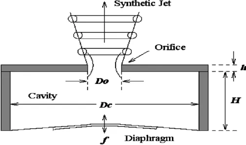
1.2.2 Working Principle
The schematic diagram of the principle of operation of a synthetic jet is shown in Figure 1.14. A typical actuator consists of a cavity open upwards through a small slot and a diaphragm or membrane which generates the flow inside the cavity. The periodic motion of the diaphragm varies the volume of the cavity. This periodic movement consists of two phases, the suction phase, when the volume of the cavity increases where the fluid enters the cavity through the slot and the blowing phase, when the volume of the cavity decreases. The movement generates a flow that separates at the borders of the slot and is transformed into a pair of vortices generated at the edges of the slot, of the "round smoke" type if the orifice is circular and two parallel vortices in the case of a rectangular orifice. These vortices moves by their own induced velocity. The repetition of the suction and blowing phases makes it possible to inject unsteady structures into the flow and to increase the efficiency of the control compared to stationary solutions such as continuous suction or blowing.
1.2.3 Characteristics parameters effecting the flow field of Synthetic Jet
Figure 1.15 summarize the different parameters effecting the flow field of Synthetic Jet for cooling of electronic components [1]:
Figure 1.15. Characteristics parameters effecting the flow field of Synthetic Jet [18].
1.2.4 Reynolds Number
Reynolds number based on velocity scale : Reynolds number based on orifice width d and velocity .
(1.1)
With
: Average over a period of time of the jet ejection velocity at Center of the orifice. Volume Synthetic jet Aspect Ratio (AR) Geometrical parameters Thickness Cavity Dimensions Amplitude Diameter Shape (Round/Slot) Height/Depth Frequency Voltage Shape Diameter Orifice Dimensions Kinematic Velocity Density D im ens ion a le ss pa ra m et e rs Fluid Parameter s Mean Velocity Actuation Parameter s Temperature Strouhal number Womersley number Reynolds number Stokes number
(1.2)
Alternatively, Holman et al [19] define another Reynolds number based on the orifice width and the space-time averages of the jet velocity at the outlet during the ejection phase
(1.3)
With
: Space-time average of the jet speed at the exit of the orifice during the ejection phase
(1.4)
: Orifice outlet section. : Transverse coordinate.
: Instantaneous velocity of the jet at the orifice outlet.
It can be noted that, taking into account the velocity profile in the outlet section of the orifice during the ejection phase, the velocity scales used to construct the Reynolds numbers and are linked by the relation :
(1.5)
Reynolds number based on the impulse
(1.6)
With:
: movement quantity per unit width
(1.7)
1.2.5 Stokes Number
The Stokes number is given by
(1.8)
Where is the slot diameter and is the oscillation speed. This formulation is typical for the studies of the synthetic jet, in other applications it is known by the name of Roshko. Holman et al [19], have shown that the criterion for the formation of structures vortices can be expressed as or for jets two-dimensional and axisymmetric synthetics, respectively.
1.2.6 Strouhal Number
Dimensionless number allows to compare the characteristic advection time of the vortex structures emitted by the synthetic jet to the characteristic working time of the actuator defined from the average velocity of the jet at the center of the orifice during the ejection phase , the frequency of membrane actuation and the width of the slot
(1.9)
And can also be expressed in terms of Reynolds and Stokes numbers
(1.10) With
(1.11)
1.2.7 Womersley number [1]
Womersley number is the dimensionless number that relates pulsatile flow frequency with the viscous effects which is defined as [20–22]
1.3
Bibliographical research on the development of Synthetic Jet
With the development of technology in the electronic field especially speed and resistance, the electronics components become more powerful and increasingly small. The components can dissipate several hundred Watts per square micro-meter, thus requires a cooling process. Several cooling techniques have been developed with the aim of improving the heat transfer rate and increasing the efficiency of the cooling systems [23]. Recently, to improve the performances of cooling and the methods of transport of heat, this with amelioration of thermal management in elec-tronic systems S.V. Garimella et al. [24]. Research studies focused on the use and the development of the cooling technique based synthetic jet.
Synthetic jets are a common method for many fluid engineering applications, such as boundary-layer separation control, jet vectoring, heat transfer enhancement, better mixing of fuel in the engine combustion chamber and creation of local turbulence. Synthetic jets can deliver similar cooling effects to conventional steady flow impinging jets without the need for an external air supply system. The main issue about synthetic jet is the enhancement of heat transfer rates or increasing of uniformity on the impingement surface by the control of jet flow. Due firstly to the important role of the synthetic jets in heat transfer enhancement techniques and secondly to the high complexity of the flow structure, the synthetic jet has received considerable research attention.
Campbell and al [25] illustrated the usage of synthetic air micro jets for powerful cooling of laptop processors while different researchers established the viable software of synthetic jets for excessive strength digital cooling via an included active heat sink [26,27]. Throbbing or discontinuous impinging planes are via and big usual to enhance the warm temperature circulate while contrasted with relentless planes, no matter the truth that there stays a scarcity of agreement at the degree of the upgrade and for sure situations the warm temperature flow may even be hindered [28,29].
T. Persoons et al. [30] imposed a margin for the Reynolds number and he modified several parameters which are the height, the diameter of the tube, the distance between the entry and the exit of the orifice, and he compared the effect of each modification on the Nusselt number. Other researchers improve the importance of the changement of the characteristics of the heated surface, Sagot. [31] imposed a change on the heated surface contact by using different corrugations and the com-parison of the results has shown that the
rectangular corrugation gives a higher Nusselt number which is better than both: the triangular corrugations and the surface without corrugation. The distance between the orifice and the heated surface is one of the major factors that influences the heat transfer by synthetic jet and have been studied and proven by many researchers experimentally [32-34] and numerically using ANSYS Fluent code where the unsteady Navier–Stokes equations and the convection– diffusion equation were solved using a fully unsteady [35], experimental study based on the characteristic of synthetic jet impinging upon a vertical heater, and results showed that the heat transfer has the higher performance with a jet-to-surface spacing between 5–10 [36]. Another experimental investigation by P. Gil and J. Wilk [37] studied the effect of the synthetic jet generated by special actuator consisting in a plexiglass cavity and a loudspeaker on the heat transfer phenomenon. the different modifications of the parameters are frequency f = 5 / 600 Hz, root mean square voltage E = 1, 2, 3, 4, 6 V and for the Changes of actuator geometry we found orifice diameters d = 9, 15, 24 mm, orifice thickness t = 3, 5, 20 mm and cavity depth H = 20, 40, 60 mm. And for the parameters: Reynolds number from 3600 to 22950, jet-to-surface spacing x/d = 1 / 20 and the dimensionless stroke length L0= 0.84 /
170.5, the results are compared and confirmed by literature data in the considered test range. Different alternative techniques have been investigated experimentally to increase the heat transfer such as the introduction of orifices into the cavity [38] or using multi-cavities is using Particle Image Velocimetry (PIV) [39, 40]. G. Paolillo et al [41] studied experimentally the influence of impinging quadruple synthetic jets for different configuration monopole-like, dipole-like, quadrupole-like and 90-degrees-circularly-shifted-jets for Reynolds = 4000 and Strouhal numbers = 0.2, results indicated that that the 90-degrees-circularly-shifted-jets configuration give the highest heat transfer rates. Luo et al [42] used an innovating technology of cooling which is based on an actuator with a double injection of vectorial synthesis dual synthetic jet in experiment work, knowing that the heat transfer influences domain has been established and validated. In other side, L.D. Mangate, M.B. Chaudhari [38] applied multiple-orifice synthetic jet for cooling the electronic components to improve the heat transfer. Chaudhari et al [43] studied the influence of the addition of orifices around the main orifice for different configurations of satellite orifices with and without the centre orifice and the results shown that the number of satellite orifices affects on the heat transfer and the satellite orifices with the centre orifice gave a relatively high heat transfer coefficient at lower axial distances. Where-as, Fanning et al [44] established two synthetic jets adjacent and they modified the height between the orifices — wall as the distance between the
two, the results proved that there is an improvement in the transferred heat and the convection coefficient.
Another factor is the shape of the opening orifice. Xiao-ming [45] investigated experimentally the efficiency of different opening hole forms including square and rectangular shapes. Results indicated that the synthetic jet with the rectangular orifice was more efficient. Furthermore, the comparison between the rectangular and the elliptic shapes are experimentally tested and showed that the rectangular orifice develops stronger streamwise vortices [46]. Chaudhari et al [47] worked on the influence of the shape of the orifice of a synthetic jet on the phenomenon of cooling by the introduction of three types of orifice: rectangular, cylindrical and square forms with a change of the parameters founded that the form square gives the maximum of heat transfer. Another experimental investigation compared a circular and chevron opening hole forms for an impinging synthetic jet and results showed that for the chevron opening hole shape the heat transfer is greater up to 20% compared to the circular opening hole shape [48].
The control of the synthetic jet in order to perform their efficiency was widely used such as acoustic excitation [49]; using multi-channel swirl generators [50]; nozzle with obstructions [51]. Several studies were carried out to increase the heat transfer rates of synthetic jets. Hsu et al [52] made a comparison of double acting synthetic jets with single-acting synthetic jets. The convective heat transfer was increased in more than two times. A double-acting synthetic jet revealed good potential with significant vorticity enhancement for the design of synthetic jet in heat transfer applications. Cadirci et al [53] showed the effect of an oscillatory zero-net-mass flux device and vortex actuator on the laminar boundary layer; it was appeared that this technique produced qualitatively different flow regimes depending on its actuation parameters. Nuntadusit et al [54] studied the flow and heat transfer characteristics of multiple swirling impinging jets. The use of this technique offered higher heat transfer rates on impinged surfaces than the multiple conventional impinging jets of all jet-to-jet distances. Thieler et al [55] studied the effect of nozzles arrangement on the heat transfer of multiple impinging jets with square/circular arrangements; it was observed that jet arrangement affects the flow characteristics with a slight influence on heat transfer. Yu et al [56] investigated the heat transfer produced by a single row of impinging jets inside a confined channel with different triangle tabs orientations at the jet exits. Results showed that the presence of tabs increased the jet core velocity, induces array pairs of vortices and enhances the heat transfer. In other work Yu et al [57] investigated the effect of the
cross-flow-to-jet Reynolds number ratio and cross-flow holes arrangement on the jet impingement behaviors. The tab-excited jet impingement behaviors in a confined channel with non-uniform cross-flow. Results showed that the effect of the tabbed excitation worsened the convective heat transfer near impingement region inside a cross-flow channel as compared to the absence of initial cross-flow. Results showed that the convective heat transfer coefficients are increased up to 25% by the tabbed excitation but only a 10% of improvement was reported for the situation with the initial flow. A new method of cooling by synthetic jet, it is by atomizing water is investigated experimentally by W. He et al [58], the idea is to use a dual synthetic jet actuator. The maximum atomization rate is 3.4 L/h at a control frequency of 700 Hz and a control voltage of 210 V, the results founded that the new method of spray cooling reaches as 59 W/cm2 and the cooling capacity is mainly influenced by the Reynolds number of the dual synthetic jet and the volume flow of water. L. Mangate, et al [59] studied the impact of a multiple-orifice synthetic jet of a circular, oval and diamond shapes are experimentally studied at different Stokes numbers, the results showed that the average Nusselt number obtained with a a multiple-orifice synthetic jet is 75% higher than with a single orifice synthetic jet using the same input power to the actuator of the synthetic jet. The diamond-shaped multiple-orifice gives better thermal performance compared to other shapes.
In the last year, a lot of experimental and numerical researchers worked to study the physical evolution between heated plan surface and caloporter fluid in high density.
A. Agrawal, G. Verma [60] gave a comparison between a continuous jet and synthetic jet where they have used the experimental results to mention the importance of the synthetic jet to the thermal transfer. Al-Atabi [61] studied the homogeneity of the fluid injected by a synthetic jet to reduce the high rate of shearing of the coolant injected and to minimize the damage to sensitive materials.
On the other side, there have been several studies that focused on the effect of the cavity shape on the synthetic jet performance and the improvement in the heat transfer characteristics. Results showed that the basic cylindrical shape maximized momentum flux and provides better performance from an experimental work [62], Lv Yuan-wei et al [63] carried out numerical investigation based ANSYS Fluent code on the effect of the cavity and orifice dimensions and the excitation frequency of the actuator on the synthetic jet fluidic characteristics. Obtained results showed that the orifice diameter and thickness, as well as the cavity depth and diameter, had major influence on the synthetic jet fluidic characteristics. Another experimental work tested the modification on the cavity using silicone elastomer
membranes together with either soft composite or rigid neodymium magnets, and they found good results for low-frequency range [64].
Heat transfer produced by a synthetic jet depends on a number of parameters such as Reynolds number of the jet, Strouhal number, stroke length, etc. It is well known that the geometry of the orifice nozzle have a significant effect on the heat transfer produced by the synthetic jet. Chungsheng Yao et al [65] investigated the effect of the jet produced by the orifice nozzles with contoured outlets. Results showed that the local heat transfer produced was up 20-30% higher than that produced by a simple square orifice nozzle.
The change in function of oscillation mode in the cavity of synthetic jet proved that the sinusoidal function is better than the triangular function [66]. Numerical investigation carried out by Zhang et al [67] in which three wave forms for synthetic jet including sinusoidal, rectangular and triangular forms for Strouhal number (St) between 0.012– 2.4 have been investigated. Reported results showed that at St < 0.06 the rectangular jet is better than the sinusoidal and triangular jets, and for St number ranging between 0.24 to 0.48, triangular jet is better. Further, numerical investigation based Computational Fluid Dynamics (CFD) and the open-source OpenFOAM code has been carried out by King and Jagannatha [68]. Results indicated that the non-sinusoidal function gave an improvement in heat transfer than sinusoidal function.
Section 2
2.1
Navier-Stokes Equations and Models of Turbulence [69]
2.1.1 Navier-Stokes Equations2.1.1.1 The continuity equation
The first equation is the continuity equation (the balance equation for mass) which reads [70]
(2.1)
Change of notation gives
(2.2)
For incompressible flow (ρ = const) we get
(2.3)
2.1.1.2 The momentum equation
The next equation is the momentum equation. We have formulated the constitutive law for Newtonian viscous fluids [70]
(2.4)
(2.5)
Inserting Eq 2.5into the balance equations, Eq (2.6), we get Eq (2.7) (2.6) (2.7) where μ denotes the dynamic viscosity. This is the Navier-Stokes equations (sometimes the continuity equation is also included in the name “Navier-Stokes”). It is also called the transport equation for momentum. If the viscosity μ is constant it can be moved outside the derivative. Furthermore, if the flow is incompressible, the second term in the parenthesis on the right side is zero because of the continuity equation. If these two requirements are satisfied, we can also re-write the first term in the parenthesis as
![Figure 1.15 summarize the different parameters effecting the flow field of Synthetic Jet for cooling of electronic components [1]:](https://thumb-eu.123doks.com/thumbv2/123doknet/14479521.715522/34.892.133.805.220.834/figure-summarize-different-parameters-effecting-synthetic-electronic-components.webp)