HAL Id: tel-00989992
https://tel.archives-ouvertes.fr/tel-00989992
Submitted on 12 May 2014HAL is a multi-disciplinary open access
archive for the deposit and dissemination of sci-entific research documents, whether they are pub-lished or not. The documents may come from teaching and research institutions in France or abroad, or from public or private research centers.
L’archive ouverte pluridisciplinaire HAL, est destinée au dépôt et à la diffusion de documents scientifiques de niveau recherche, publiés ou non, émanant des établissements d’enseignement et de recherche français ou étrangers, des laboratoires publics ou privés.
Yann Le Coq
To cite this version:
Yann Le Coq. Optical frequency combs and optical frequency measurements. Optics [physics.optics]. Université Pierre et Marie Curie - Paris VI, 2014. �tel-00989992�
Peignes de fréquences et mesures
de frequences optiques
HABILITATION À DIRIGER DES RECHERCHES
Soutenue le 28 janvier 2014par
Yann LE COQ
Composition du jury :
Pr. Patrick Gill (NPL) Rapporteur Dr. Vincent Giordano (FEMTO-ST) Rapporteur Dr. Martina Knoop (PIIM) Rapporteur Dr. Christophe Salomon (LKB) Examinateur Dr. Daniele Romanini (LiPhy) Examinateur
Travail de recherche présenté effectué à
LNE-SYRTE, UMR8630 CNRS/UPMC/Observatoire de Paris Paris, France
National Institute of Standards and Technology, Time and Frequency Division, Boulder, CO, USA.
I am grateful to Martina Knoop, Vincent Giordano and Patrick Gill to have accepted to act as reviewers on my ”Habilitation”. They were willing to take some time from their busy schedule to read this manuscript and provide the report, as well as useful comments and advice for improvement and I appreciate their time and efforts. Christophe Salomon was kind enough to preside the defense jury and I am thankful for that as well as to Daniele Romanini who also accepted to be part of my jury.
Institut d’Optique Graduate School
Although not much is said in this manuscript about my first post-doctoral experience at Institut d’Optique, I spent 2 great years there, interacting with several people of which I have many fond memories. Alain Aspect and Philippe Bouyer kindly offered me to stay working with them after my doctorate and to entrust me with the many technical and management aspects of the construction of the second Rubidium BEC apparatus. Many a thing I know today (both technical and human), which make me the scientist I am, owe a lot to their patronage at that time, and I thank them for it. We started the adventure of the second Rb BEC apparatus with an empty room and a lot of enthusiasm with Marie Fauquemberg, who was then starting her PhD and, for a while, the help of Effrossini Tsoushnika and, briefly, Signe Seidelin, as interns. We were joined later by Jean-Félix Riou and, at the end of my postdoc, by William Guerrin and were helped for a while by Karsten Van Nielsen as a visiting PhD student. I have strongly appreciated interacting with them. Facing together with them the ups and downs of the construction from scratch of a complex scientific apparatus was definitely a great experience. Despite the difficulties and the high workload, we never stopped enjoying ourselves at work together and manage to operate as a team both efficient and fun to be a part of. At the end of my postdoc a Institut d’Optique, I was also interacting regularly with the people in charge of building what was to become the ICE experiment (an atom interferometry experiment that flew in the zero-gravity aircraft). I enjoyed very much working with Robert Nyman and Gael Varoquaux at that time. During all my stay in the Atom Optics group at Institut d’Optique, I really enjoyed the strong and efficient technical support that Frederic Moron and André Villing were providing in electronics. Michel Lécrivain from ENS Cachan played a major role in the design and realization of the Rb atom trapping electro-magnet and our interactions were very productive and interesting. After I moved to Boulder, I kept working for a while, on the side, with William and Jean-Félix, with extra help from Francois Impens and Christian Bordé on theoretical aspects of atom laser propagation. These were some very stimulating interactions which resulted in my only purely theoretical paper so far. This
was definitely an enriching experience that I am very happy about. I particularly enjoyed our way of using the time difference between Boulder and Orsay to provide an almost constant flow of new ideas, tests, simulations and calculus on atom laser propagation.
NIST, Boulder, Colorado, USA
Although I had no prior experience on time and frequency metrology, Leo Hollberg and Chris Oates were kind enough to hire me as a guest researcher at NIST in Boulder, for which I am truly grateful. I also interacted scientifically with the comb part of the group which was under supervision of Scott Diddams with whom I was very glad to work. Leo, Chris and Scott were leading scientific teams which they managed to make both extremely high level, among the best in the world, and very friendly and human. I strongly appreciate this aspect of their leadership. My stay there introduced me to the arcane of optical frequency metrology which became the core of my current activity and the present manuscript. I feel very lucky to have been in Boulder at this time, one of the best places in the world for this reasearch topic. I often interacted at NIST with Tara Fortier and Jason Stalnaker through the use of the optical frequency comb and learned many a useful thing on these devices from them. Working with them was both extremely enriching and very fun. I also worked with Davy Ortega, who was spending a part of his time as a PhD Student at NIST, and I particularly enjoyed his enthusiasm and energy. I shared many interesting discussions and good meals with many members of the optical frequency metrology group at NIST, including, in addition to previously mentioned people Qudsia Quraishi, Vela M’bele, Mat Kirchner, John Kitching, Svenja Knappe, Elizabeth Donley with occasional participation of Tom Heavner from the atomic fountain group. As a part of the Time and frequency division, we were also in regular scientific and friendly interaction with people from other parts of the building. I want to give a special recognition to Jim Bergquist, whose help in difficult situations, both in science and life has been a great source of inspiration. I am also indebted to the scientific collaboration with Nathan Newbury and Ian Coddington on Fiber-based femtosecond lasers which has been very productive and enriching. Through Signe, I was in frequent connection with people from the ion storage group, both for fun and science and I thank them for their help and friendship. I also owe a lot to our colleagues at JILA in the Jun Ye’s group Strontium clock team whose collaboration and efficiency on the Strontium-Calcium experiment was paramount.
LNE-SYRTE, Paris, France
Pierre Lemonde was the leader of the Optical frequency metrology group at LNE-SYRTE in Paris when he asked me to join, in order to work on the optical frequency combs there. I am very grateful for the opportunity he gave me then and his support and help for getting the permanent position I currently hold. Philipp Tuckey and Noel Dimarcq have been the directors and vice-directors of LNE-SYRTE and SYRTE (in this or that order) over the years I have spent in this laboratory so far, and I thank them for their hard and difficult work and their constant support over the years. I have had
a particularly strong and efficient collaboration during most of my stay at LNE-SYRTE with Giorgio Santarelli on the femtosecond laser activity and most particularly on low phase noise microwave generation. Giorgio has taught me many of the black magic behind microwave phase noise and it has always been extremely thrilling to discuss new ideas and strategies with him. Now that he has left SYRTE for new challenges at LP2N in Bordeaux, I hope the best for him there and hope our friendship and collaboration will keep enduring. Sebastien Bize is the current group leader of the optical frequency group after Pierre left for other horizons in 2010. It has been a real pleasure to work with Sebastien ever since the first day I arrived at LNE-SYRTE and it is now a privilege to be part of the research team he leads. His friendship, advice and support have been a constant guidance in science and work-ethics throughout these years and I am grateful for it. Michel Lours, as manager of the electronic technical support service has constantly been an amazing source of help with many of the hard-core technical aspects of low noise and large bandwidth electronics. I have many times relied on his vast knowledge of techniques and components and have much enjoyed working with him along these years. As the person in charge of the femtosecond laser activity, I have had the great opportunity to interact with the various optical clocks people: Sebastien Bize, Jerome Lodewyck and, more recently, Rodolphe Le Targat and Luigi de Sarlo for the permanent staff, as well as other permanent members of the optical frequency group and microwave primary frequency references team (Paul-Eric Pottie, Ouali Acef, Peter Wolf, Michel Abgrall, Daniele Rovera, Phillipe Laurent, Peter Rosenbusch, Jocelyn Guéna). Such interactions have always been a great source of learning and progress in our common metrologic goals. My research activity owes a great deal to the interns, PhD students and post-doc I have had the opportunity to work closely with over the years at LNE-SYRTE. Jacques Millo, Elizabeth English, Wei Zhang, Daniele Nicolodi, Bérangère Argence, Adil Haboucha, Tang Li, Sylvain DiManno and Catxere Andrade Casacio on the frequency comb activity and low-noise microwave generation, as well as Katharina Predehl and Olivier Gobron on the more recent spectral-hole burning-stabilized laser activity. Wei and Daniele’s work in particular have been central for pushing the comb’s performance to the next level. I have shared many interesting discussions, scientific or not, with the various members, permanent and not permanent, scientific, technical or administrative, of the optical frequency group and the whole SYRTE laboratory in general. A full list is impossible to fit in here, but may they all be thanked collectively for the good spirit they manage to keep, despite the very demanding workload. The work on low-noise microwave generation with optical frequency comb has been done in part in collaboration with the “Franche-Comté Electronique, Mécanique, Thermique et Optique - Sciences et Technologies” (FEMTO-ST) institute from Besançon who dedicated their own frequency comb to this project for more than 1 year. The main FEMTO-ST people involved in this collaboration were Yann Kersalé, Rodolphe Boudot and Zenyu Xu. Andre Luiten was a visiting scientist from University of Western Australia during the time of this LNE-SYRTE/FEMTO-ST collaboration and I have had the great pleasure to work with him. The frequency comb referencing part of the long-distance telecom fiber optical link project lead me to interact closely with the “Métrologie, Molécules et Tests Fondamentaux” group at Laboratoire de Physique des Laser (LPL) at Villetaneuse. We have been interacting with Anne Amy-Klein, Christian Chardonnet and Benoit Darquié
in this collaboration and will continue doing so, especially with the development of the REFIMEVE+ project (distribution over the telecom network of optical frequency metrologic reference on the national and european level), jointly managed by LNE-SYRTE and LPL (and Laboratoire de Photonique, numérique et Nano-science”-LP2N, now that Giorgio has moved to this newly created laboratory), for which the frequency comb activity will be closely integrated. I hope this long standing collaboration will be rich and productive.
As a final word, I want to thank Signe for her constant help, support and encour-agement throughout the years without which nothing would have been possible.
Introduction and work presentation 9
1 Optical frequency measurements 13
1.1 Optical frequency comb principles . . . 14
1.2 Optical frequency combs at LNE-SYRTE . . . 17
1.2.1 Titanium-sapphire based system . . . 17
1.2.1.1 Description of the laser . . . 17
1.2.1.2 Phase-locking of the comb onto a 1062.5 nm cw laser, narrow linewidth regime . . . 18
1.2.2 Erbium-doped fiber based systems . . . 20
1.2.2.1 Description of the lasers . . . 20
1.2.2.2 Phase-locking the comb onto a 1.5 µm cw laser in the narrow-linewidth regime . . . 21
1.2.3 Measuring the repetition rate . . . 22
1.2.4 Determining the index of the comb mode . . . 23
1.3 Overview of my work on optical frequency measurements . . . 25
1.4 Personal publications relevant to this chapter . . . 30
2 New applications of frequency combs in the microwave domain 33 2.1 Phase and amplitude noise of an oscillator, mathematical definitions, properties and measurement in the microwave domain . . . 34
2.2 Low phase noise microwave sources and optical frequency combs . . . 36
2.3 Application to fountain clocks and first experiments . . . 38
2.4 Copying the cw laser spectral property on a large Fourier frequency range 40 2.4.1 Feed-forward technique . . . 40
2.4.2 Intra-cavity EOM . . . 40
2.5 Limiting the effect of amplitude phase conversion . . . 41
2.5.1 Active stabilization . . . 41
2.5.2 “Magic points” of the photo-diode . . . 43
2.6 Increasing the signal to-noise ratio . . . 44
2.6.1 High linearity photo-diodes . . . 46
2.6.2 Repetition rate multiplication . . . 47
2.6.3 dual-photo-detector combined with repetition rate multiplication . 48 2.7 Chapter conclusion . . . 49
3 New applications of Frequency combs in the optics domain 53
3.1 Direct frequency comb spectroscopy . . . 54 3.2 Multiple frequencies optical network over 100’s of meters and 100’s of
Tera-Herz . . . 57 3.3 Transfer of spectral purity between wavelengths at the 10−18 level . . . . 57 3.4 Remote spectroscopy in the mid-IR . . . 60 3.5 Personal publications relevant to this chapter . . . 62
Conclusion and perspectives 63
[...] ἰ ό οῦ ο ἔ νῦν ὖ έ μ ῆ ὀπά .
Ἀ ὰ ὶ ὧ ἱππ ῦ μ έ ομ ἠ ὲ ύ ω
ο ῇ ὶ μύθο · ὸ ὰ έ ἐ ὶ όν ων.
Αἰ μὰ ᾽ ἰ μά ο ν ώ ο , οἵ π ἐμ ῖο
ὁπ ό ο ά π ποίθ ίν ί ν.
As I was then a youth, so now doth old age attend me. Yet even so will I abide among the charioteers and urge them on by counsel and by words; for that is the office of elders. Spears shall the young men wield who are more youthful than I and have confidence in their strength.
Homer, Iliad, book IV, verses 321-325 (Translation by A. T. Murray, PhD)
Atomic clocks that work in the micro-wave domain (i.e. at a frequency of a few GHz) are currently at the base of the realization of the SI second and the “Temps Atomique International” (TAI) - atomic international time. They are progressively reaching their intrinsic limit, and systems that operate in the optics domain (i.e. at a frequency of a few hundred THz) are expected to progressively replace them in the next few decades.
These systems in the optics domain operate by probing an ultra-narrow atomic tran-sition with a cw laser of extremely high stability and spectral purity (usually less than 1 Hz linewidth). By locking the laser’s frequency to the resonance of the probed optical transition, one realizes an optical frequency standard1. The short term frequency stabil-ity of such standards (currently a few 10−15 at 1s) greatly surpasses that of microwave frequency standards (based on Cesium or Rubidium), which is, in itself, a strong motiva-tion for developing them. Furthermore, a better stability also provides an easier, faster and more convenient characterization of systematic bias that may impact the frequency standard. In term of accuracy, many effects are insensitive to the reference frequency (Zeeman effect, density shift, for exemple), and therefore become relatively smaller when compared to an optical frequency than to a microwave frequency. The effects related to the movement of the atoms (Doppler effect, recoil effect) are the only ones which induce shifts proportional to the frequency, but this particular point has been solved for optical clocks either by confining the atoms in an optical lattice (neutral atoms), or in an ion
1the terms “optical frequency standard” and “optical clock” are used very often, somewhat abusively,
to describe the same kind of setup. Rigorously, a frequency standard produces an oscillating signal which is frequency stable and absolutely referenced to primary standards. A clock includes a frequency standard, but also the surrounding systems that allow to use it to actually measure the passing of time.
trap (charged particles).
The advantage of using optical frequency standards is therefore particularly clear. The inconvenient lies in the fact that the actual signal produced by such frequency standard is an electro-magnetic field in the optical frequency domain, which exhibits an oscillation frequency of several hundreds of THz: no electronic system is fast enough to count it or compare it to other frequency standards, either optical (operating at other wavelength) or microwave.
Before the invention of optical frequency combs, the only possibility to realize opti-cal frequency measurements were involving extremely complex frequency multiplication chains, with tens of lasers, and very manpower consuming. Only a handful of labo-ratories worldwide had access to such technology. Optical frequency combs, based on self-referenced femtosecond lasers [1, 2], allow such measurement with a simple, compact (approx. 1 m2 of optical table), reliable and, nowadays, commercially available device.
Optical frequency chains of old time were, on the contrary, extremely complicated apparatuses, designed for a single very specific wavelength measurement, and requiring half a dozen of highly trained specialists to operate (and even then, only so rarely, a few times a year at best in the handful of institution that sheltered them). Optical frequency combs are now ubiquitous tools which have revolutionized the domain of optical frequency metrology by providing a phase coherent link over the optics and microwave domain, thereby covering hundreds of THz of spectrum with a single device of moderate complexity.
Their relative simplicity of operation, wide optical spectrum and high performance have also allowed the blooming of a very rich domain of applications, where they have shown their usefulness beyond the relatively narrow circle of highest-performance optical clocks community. Research with optical frequency combs includes, nowadays, applica-tion in the microwave domain (sources for radar and telecommunicaapplica-tion), tera-Hertz (as sources of radiation and frequency control), mid-infrared, optical and VUV-XUV range. Scientific communities as various as radio-astronomers, optical domain astronomers, par-ticle accelerator operators, free electron lasers researchers and, of course spectroscopists with various fields of interest are showing interest for these tools.
My working in the field of optical frequency combs and optical frequency measure-ments started at the National Institute for Standards and Technology (NIST) in Boulder, Colorado, USA, during my stay as a guest researcher in 2004-2007. My original field of research was Bose-Einstein condensation of laser-cooled neutral atoms []. After a PhD thesis in this field, under the supervision of Alain Aspect and Philippe Bouyer at Insti-tut d’Optique, I pursued working in this group where I, along with three undergraduate students and various interns, had the opportunity to build from zero a high performance Rubidum Bose-Einstein condensation experimental apparatus. This two-year long post doc position led me to publish several papers in the field of atom laser realization and analysis [3, 4, 5, 6], as well as precision measurement using Bose-Einstein condensation [7]. The present manuscript doesn’t describe these experimental and theoretical contri-butions, as I preferred keeping the scope of this manuscript to one single field. a list of the papers in peer-reviewed international journals that were published in relation with this work is given at the end of the introduction.
Boulder, in the group of Leo Hollberg, where I was working on a cold neutral calcium optical atomic clock and with optical frequency combs in 2005-2007. After this stay abroad, I was recruited at LNE-SYRTE in Paris Observatory to take in charge the optical frequency comb activities in the optical frequency measurement group. I have been doing research in this institution since then.
In the present manuscript, I have divided my various research projects at NIST and LNE-SYRTE along three main themes. The first chapter describes the realizations that I was a part of in the domain of optical frequency measurements. This includes detailed description of how to actually measure the signal from an optical clock with a frequency comb and a description of the results of the various measurement campaigns that I was involved in over the years. The second chapter describes my work in the field of ultra-low phase noise microwave signal generation with optical frequency combs. The third chapter describes various experiments I have worked on, which demonstrate new utilization possibilities of frequency combs in the optics domain. The first and third chapter mix work that was realized at NIST and LNE-SYRTE, while the second chapter covers a research program that I worked on exclusively at LNE-SYRTE.
The separation in three chapters is, of course, somewhat arbitrary, as many technical and fundamental problems were found indiscriminately in the three lines of research, and solving them in one context benefited the others greatly. For example, generating low noise microwave signal with a frequency comb renders the absolute frequency measure-ment of an optical clock against a primary frequency reference much more efficient. To be capable of quasi-autonomous operation of combs for hours and days, as is required for optical frequency measurement, makes the study of transfer of spectral purity between optical wavelengths and between optics and microwave much more convenient as one can rely on robust and reliable apparatus, etc.
As a general rule of research in the field of metrology, the real progress in the long run can only be obtained from a highly advanced, yet reliable technology. Indeed, at NIST and LNE-SYRTE, which are both National Metrology Institutes, researchers are strongly encouraged to design reliable and autonomous experiments, as, in the long run, they are supposed to be operated continuously with minimal human intervention. Whereas this could be considered a burden, this is also a strength as they then provide a reliable and solid ground on which to build highly ambitious research programs. This is a strong specificity of experimental research in National Metrology Institutes that cannot be emphasized enough.
Personal publications relevant to my post-doctoral work at
Institut d’Optique on Bose-Einstein condensation and atom
lasers
Partially ferromagnetic electromagnet for trapping and cooling neutral atoms to quantum degeneracy
M. Fauquembergue, J.F. Riou, W. Guerin, S. Rangwala, F. Moron, A. Villing, Y. Le Coq, M. Lécrivain, P. Bouyer and A. Aspect
Rev. Sci. Instrum. 76, 103104 (2005)
Beam Quality of a Non-ideal Atom Laser
J.-F. Riou, W. Guerin, Y. Le Coq, M. Fauquembergue, V. Josse, P. Bouyer, and A. Aspect
Phys. Rev. Lett., 96, 070404 (2006)
Coherent matter wave inertial sensors for precision measurements in space
Y. Le Coq, J. A. Retter, S. Richard, A. Aspect and P. Bouyer App. Phys. B, 84, 627-632 (2006)
Tapered-amplified AR-coated laser diodes for Potassium and Rubidium atomic-physics experiments
R. A. Nyman, G. Varoquaux, B. Villier, D. Sacchet, F. Moron, Y. Le Coq, P. Bouyer and A. Aspect
Rev. Scient. Instrum., 77, 033105 (2006)
Theoretical tools for atom-laser-beam propagation
J.-F. Riou, Y. Le Coq, F. Impens, W. Guerin, C. J. Bordé, A. Aspect and P. Bouyer Phys. Rev. A., 77, 033630 (2008)
Optical frequency measurements
One should avoid carrying out an experiment requiring more than 10 per cent accuracy.
Walther Nernst (1864-1941), physicist and chemist. Quoted in [8].
The optical frequency measurement is the prime application of frequency combs and historically the most developed worldwide. I describe in this chapter the work I have realized in connexion with optical frequency measurements at LNE-SYRTE and NIST. At NIST, I was working primarily on a simple and robust cold atom optical frequency standard based on neutral Calcium that served as a high long term stability reference, allowing the full characterization of systematic errors of a state-of-the-art neutral Stron-tium lattice clock at JILA [9]. The measurement campaigns were realized thanks to an optical fiber link between the two institutions (distant by 3km), and optical fre-quency combs at each end of this link to connect it to the wavelength of operation of the Strontium and the Calcium clocks.
My work at LNE-SYRTE is mostly centered on the comb part, in strong interaction with the people working on the optical frequency standards per se. This includes many measurement campaigns of the two Strontium lattice clocks [10, 11, 12], the one neutral mercury clock of the laboratory [13, 14, 15, 16, 17, 18], as well as some long-distance measurement of the CO2/OsO4 mid-infrared frequency standard located at Laboratoire de Physique des Lasers (LPL) in Villetaneuse, via an optical fiber link between this laboratory and LNE-SYRTE [19].
I begin with a general introduction to the concepts and techniques related to optical frequency combs. This can be considered a short “technical-tutorial-like” introduction to the subject, presenting concepts that are fundamental for the rest of the manuscript. I proceed with a description of the system, techniques and setups used nowadays at LNE-SYRTE for optical frequency measurements. This description gives an overview of present day state-of-the-art fiber-based frequency comb system. Although not exactly equivalent to the systems used at NIST and JILA while I was there (Titanium-sapphire based systems with phase-locking of both f0 and frep were, and are still, the technique of choice there1), the system I describe can be considered as a good example of a reli-able device that allows measuring any present-day optical frequency standards without degradation in terms of stability or accuracy.
I finish by giving an overview of the various experiments that I participated in over the years which relate to optical frequency measurements.
1The definition of the parameter f
1.1 Optical frequency comb principles
The electromagnetic field emitted by a mode-locked femto-second laser is composed, in the frequency domain, of a series of modes, regularly spaced in frequency, and phase coherent with each other. The frequency of each mode thus follows the relation
νN = N × frep+ f0 (1.1)
where frep is the repetition rate (typically radio-frequency) of the laser pulses, νN is the optical frequency of the considered mode, N a large integer (typically of the order of 106), and f
0 is a global shift frequency called “carrier-envelop offset frequency”. This last term is related to the difference between the phase velocity and group velocity in the laser oscillator. It corresponds, in the the time domain, to the fact that the electric field is not strictly identical from one pulse to the next, but exhibits a phase shift with reference to the time envelop of the pulse (see figure 1.1)
Figure 1.1: Correspondence between the time (successive pulses) and frequency domains (regularly spaced modes) for the electromagnetic fields generated by a mode-locked fem-tosecond laser of repetition rate frep. The dephasing ΦCE between the envelop and the optical carrier that arise between two successive pulses corresponds, in the frequency do-main, to a global shift of the frequency of the modes by a offset f0 = 2π1 dΦdtCE = Φ2πCEfrep. By mixing (on a partially reflecting mirror or a fibered beam-combiner) the electro-magnetic fields generated by a femtosecond laser and a cw laser whose frequency νcw needs to be measured, and detecting the result with a fast photo-diode (of which the bandwidth will be denoted fBW), one gets a radio-frequency signal whose spectrum is composed of, for one part, harmonics of the repetition rate frep, and, for another part, different optical beat-notes with frequencies fb,N= |νcw−N ×frep−f0|, with the integer
N taking all the values such that fb,N < fBW. One can then easily isolate from this complex signal, using a sufficiently narrow radio-frequency band-path filter, one of the fb,Ncw components which provides the frequency shift of the cw laser with one on the modes of the femtosecond laser, indexed by the integer Ncw.
Likewise, with another narrow band-path filter, one can isolate one of the harmon-ics of frep, which provides access to this value. In practice, it’s however common to physically split the measurement of frep and fb,N on two different photo-diodes, so as to optimize the detection for these two signals separately. For example, optimizing the signal-to-noise ratio of the beat-note fb,Ncwnormally requires to limit the spectrum of the
femtosecond laser that illuminates the photo-diode to a narrow spectral width around the optical frequency νcw. Otherwise, using the full spectrum of the femtosecond laser would produce a very large number of components with frequencies fb,N higher than fBW, which produce shot-noise without producing a useful signal. To decrease as much as possible this added shot-noise by filtering the spectrum around its “useful domain” can therefore greatly increase the signal-to-noise ratio of the beat-note at frequency fb,Ncw.
This is typically done with a narrow interferometric filter with a spectral bandwidth of 1 nm or below. In contrast, the optimal detection of frep requires to use the maximum available optical power (within the limit imposed by the photo-diode saturation), so as to maximize the detection signal-to-noise ratio. Furthermore, in this case, we have shown how some specific operation regime can greatly reduce the residual measurement noise of frep, and therefore enables the use of the detected signal, for instance, as an ultra-low phase-noise microwave source (see chapter 2). These solutions, at the current stage of our research, can only be used reliably when a specific photo-diode is dedicated to the sole detection of frep (or of one of its harmonics).
If the integer Ncw is known, or at least easy to determine (for example in the case where the frequency νcwis already known with a better accuracy than the repetition rate frep), f0 is the only remaining frequency to determine for completely defining the equa-tions, and therefore measuring absolutely the optical frequency νcw. The measurement of f0 is realized by the self-referencing technique, which requires the femtosecond laser to exhibit a spectrum that spans at least one octave (i.e. from one optical frequency to its double for the so-called f-2f technique2). In practice, very few lasers exhibit such a wide spectrum “naturally” (so far, only ultra-short pulses Titanium-Sapphire based lasers with pulse duration of 3 to 5 fs approximately have been shown to exhibit such a wide spectrum, see for examples [21, 22, 23, 24]). Nevertheless, using a piece of highly non-linear fiber allows to broaden the spectrum of a few types of short pulses femtosecond lasers, sufficiently to reach the octave spanning condition while maintain-ing the phase coherence condition between modes that is necessary for the operation of the self-referencing technique3. These highly non-linear fibers are engineered so as to exhibit a quasi-vanishing chromatic dispersion near the central wavelength of the
2Some self-referencing experiments have been realized with spectrum covering only two third of an
octave, see for example [20]. They require an even higher level of sophistication and are not widely used nowadays
3Many lasers can reach an octave spanning spectrum by propagating in a long enough
dispersion-managed non-linear fiber, provided they can reach a high enough peak intensity. One can buy, nowadays, such “white light lasers” from various providers. However, maintaining the coherence between the two sides of the octave spanning spectrum is an entirely different business.
femtosecond laser. This allow the pulses to propagate in them while keeping a short duration and therefore keep a high peak intensity along the propagation, which in turns provide the requirement for high non-linear effects. By successive 4-wave mixing pro-cesses (both degenerate or non-degenerate for the various possible mode combination) between the various modes that compose the femtosecond laser spectrum, the non-linear fiber progressively broadens the spectrum until there is a factor equal or higher than two between its low and high frequency sides, which the a prerequisite for the self-referencing technique. Thus, it appears in the spectrum a component at optical frequency νN = N × frep+ f0 and another one, at the other end of the spectrum of frequency ν2N = 2N × frep+ f0. By doubling the frequency of the component νN in a non-linear crystal, and detecting the optical beat-note between this signal of frequency 2 × νN and the mode of frequency ν2N with a fast photo-diode, one gets a signal at frequency |2N × frep+ 2f0 − 2N × frep− f0| = f0. The frequency doubling acts on several optical modes at the same time. The final signal therefore contains, in addition, harmonics of the repetition rate frep, but also components at frequencies M × frep± f0 with M an integer. It is however easy to remove those components with sufficiently narrow radio-frequency bandpass filters. It is important to notice that the participation of a large number of pair of modes of frequencies 2νN and ν2N to the signal is actually favorable, since several pairs will produce beat-notes that may add coherently to pro-duce a signal of much larger amplitude than would be propro-duced by a single pair. As the typical optical power per mode is of the order of a few pW, this coherent build up is actually essential to the detection. However, it can only happen if every pair produces a signal of frequency f0 with identical phase as the others, which requires a fine tuning of the global dispersion of the optical systems that realize this f-2f interferometer (the optical path for components of frequency ν2N and for components of frequency νN be-fore, while and after the frequency doubling must be identical). This phase matching condition is actually equivalent, in the time domain picture, to ensure that the parts of the pulse which have been frequency doubled, and that which haven’t, reach the photo-diode at the same moment. This condition can for example, simply be realized with an adjustable delay line that acts only on part of the optical spectrum (before the fre-quency doubling stage), or with ad hoc fixed dispersion elements (glass plate or negative dispersion mirrors) added in the optical path.
The set of radio-frequency signals fb,Ncw, frep and f0 gives all the parameters that completely define the system of equations, and therefore provides a mean to compare optical to microwave frequencies. Furthermore, when using several beat-notes between the optical frequency comb and several cw lasers (operating at different wavelengths), fb,N(1)
cw, fb,N(2)cw, fb,N(3)cw, etc. one can compare simultaneously several optical frequencies,
without necessarily using the intermediate of the micro-wave domain. Nevertheless, these measurements assume that the mode indices N(i)
cw are previously known. The easiest way to determine those is when the optical frequency to measure is known beforehand with an accuracy better than the comb’s repetition rate. Indeed, in this case, it’s easy to locate the mode closest to νcw. In the particular case of optical clock transitions whose frequency is known with a very large accuracy (for the “classic” clock transitions like for neutral Strontium for example), this condition is naturally fulfilled. For non-absolute optical frequency standards, like a high-finesse Fabry-Perot cavity not
in relation with an atomic transition, or an atomic clock transition that hasn’t been measured previously (as was the case for the first neutral mercury experiments at LNE-SYRTE), this previous knowledge of the optical frequency is normally not sufficient as the best commercially available wavemeters don’t provide, in general, an absolute accuracy of a few MHz or tens of MHz, as required, for an arbitrary wavelength (in the best case, such accuracy is only available a few nm away from a fixed calibration wavelength). Realizing several measurements using different repetition rates of the comb, assuming the optical frequency to determine doesn’t change too fast in-between the measurements, and the measurements themselves are realized with a sufficiently high resolution, one can however deduce the integer indexes of modes with basic mathematics. If one has access to two working combs, one can even make the measurement with the two combs (operating at different repetition rates) simultaneously (or, even better, synchronously) [25, 26], thereby greatly relaxing the necessity for the optical frequency which is measured to exhibit small fluctuations, as well as the necessity of high resolution measurement.
1.2 Optical frequency combs at LNE-SYRTE
The LNE-SYRTE owns several optical frequency combs based on two different technolo-gies. The combs based on Titanium-sapphire femtosecond lasers appeared in the year 2000 and allowed the measurement of many optical frequencies in the visible domain and the near infra-red. Their operation for more than a few hours or a day is gener-ally still a challenge for the high repetition rate lasers that are preferred for metrology applications. A new generation of comb, based on fiber lasers, that we started working on in 2009 at SYRTE, are progressively replacing the Titanium-Sapphire based systems for operational level measurement tools. Our work in collaboration with our industrial partner (MenloSystems GmbH) has allowed these fiber-based optical frequency combs to reach the current state-of-the-art and these devices are progressively taking over for measurement campaigns at LNE-SYRTE.
1.2.1 Titanium-sapphire based system
1.2.1.1 Description of the laser
The first generation of optical frequency combs at LNE-SYRTE uses, as a femtosecond laser oscillator, a titanium ion-doped sapphire crystal in a free-space resonant cavity. This system is pumped by a continuous 8 W commercial laser at 532 nm, based on intra-cavity frequency doubling of a neodymium YAG laser. The mode-locked pulsed operation is realized by Kerr-lens effect in the Titanium-Sapphire crystal itself. The repetition rate is close to 767 MHz, finely tunable with a piezo-electric actuator mounted on one of the mirrors of the cavity. The pump beam, before reaching the laser oscillator, is passing through an acousto-optic modulator (AOM), used in the 0th order, which allows fine tuning of the effective pumping power. This fast actuator allows typically to provide feed-back with a bandwidth near 400 kHz,and acts both on the frequency f0 and the repetition rate frep, by modifying the index of refraction and the dispersion seen by the femtosecond laser in the titanium-doped crystal. A motorized glass wedge also allows a coarse adjustment of the f0 frequency, by adding or removing a dispersive
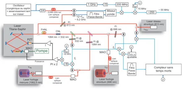
glass thickness in the laser cavity. The pulses that are produced by this laser, typically 30 fs in our case, are send, in parallel, on a fast GaAs photoconductor (to detect frep and its harmonics up to 14 GHz), and on a 20 cm non-linear photonic crystal fiber which produces at its output a quasi-continuum that covers more than one octave of spectral bandwidth (from 520 nm to 1100 nm approximately). Several free-space optical elements allow to generate from this wide spectrum the self-referencing f0 signal and the optical beat-notes between the comb and several cw lasers to measure at LNE-SYRTE: clock (698nm) and trapping (813 nm) lasers of the Strontium optical frequency standards, clock (1062.5 nm before frequency quadrupling for interrogation of atoms at 265.6 nm) laser of the neutral mercury optical frequency standard and an iodine-stabilized laser (1064 nm). The general setup schematic for the Titanium-Sapphire optical frequency comb at LNE-SYRTE is represented on figure 1.2.
1.2.1.2 Phase-locking of the comb onto a 1062.5 nm cw laser, narrow linewidth regime
The beat-note signal at at λcw= 1062.5nm exhibits a large signal to noise ration (>50dB in a 500kHz bandwidth). We use this property to phase-lock the comb to the ultra-stable laser at this wavelength with a large (>400kHz) feed-back bandwidth4. This beat-note signal is, like any other optical beat-note amplified and mixed with the f0 signal. After this mixing, we obtain mainly two components at frequencies νcw− Ncwfrep− f0 + f0 and νcw− Ncwfrep− f0− f0, but only the first is independent of f0 and its fluctuations. We isolate this radio-frequency component with a narrow band-pass filter and divide its frequency by 8. This digital division step is used to increase the phase-lock loop reliability by decreasing the probability of cycle-slips occurrence. We beat the result against a fixed frequency reference made with a synthesizers referenced to the primary standards of the laboratory. After low-pass filtering, the error signal obtained is processed in an analog corrector, implementing proportional gain plus multiple integrators, which acts, for high Fourier frequencies to the optical pump power (via the 0 order AOM at 532 nm) and for low Fourier frequencies (<1 kHz) on the piezo-electric actuator that tunes the length of the femtosecond laser cavity. This realizes a phase-lock loop which connects the repetition rate of the pulsed laser with the optical frequency of the cw laser via the relation:
νcw− Ncwfrep
8 = fREF (1.2)
In practice, we do not necessarily use the comb mode nearest to νcw, but choose a beat-note at a frequency sufficiently far from spurious or unwanted beat-beat-notes to facilitate its isolation from the rest of the signal. Because of this phase-lock loop, we therefore connect two frequency domain of the electromagnetic spectrum separated by more than 5 orders of magnitude (radio-frequencies and optical frequencies), via an integer division factor Ncw and a fixed frequency shift fREF.
It’s not necessary to precisely know f0, as this quantity is removed from the beat-notes by RF mixing. It is sufficient to ensure that the relative electronic and propagation
4The rule a thumb for phase lock-loops is that the signal-to-noise ratio of the beat-note used to
generate the error signal must be higher than ≈23-30 dB in a given bandwidth B to be able to phase-lock with a unitary gain bandwidth of approximately B.
PI x 2 PZT I ~ 15 MHz ~ 40 MHz ~ 55 MHz f0 f0 Compteur sans temps morts 12 xfrep ~ 9,2 GHz Laser Titane-Saphir fREF Lien optique compensé µ Laser horloge mercure (1062,5 nm) νHg MAO Filtre Passe-Bande 200 MHz 1 GHz Mixeur µonde x200 MAO µ fDDS, Sr ajustable Pompe MAO FI @ 813 nm Laser horloge strontium (698 nm) νSr Filtre Passe Bande Lien optique compensé /8 Laser réseau strontium (813 nm) νRes µ Puissance FI @ 698 nm 3/4 ~ 8,985 GHz sur Lien optique compensé Oscillateur cryogénique au saphir + asservissement lent sur maser fREF / 5 CNL 1064 nm -> 532 nm FI @ 532 nm FI @ 1064 nm µ FHNL
Figure 1.2: Setup schematics of the Titanium-Sapphire based optical frequency comb currently used at LNE-SYRTE for optical frequency measurements.
delays between f0 and the optical beat-note are small to provide f0 suppression on a large Fourier frequency domain (normally larger than the bandwidth of the phase-lock loop without particular precautions). After the optical beat-note is removed from f0, the resulting signal exhibits a spectral purity as good as that of the laser on which the optical frequency comb is phase-locked. This is a consequence of the fact that the large feed-back bandwidth achievable with the phase-lock loop (>400kHz) allows reaching the narrow-linewidth regime, also called “ultra-stable” regime, in which the residual phase noise from the loop itself is negligible and in which, consequently, every tooth of the comb (virtually, once f0 is removed) possesses the same spectral purity as the optical reference to which the comb is phase-locked. When the experimental conditions are not met for reaching the narrow-linewidth regime (free-running noise of the laser too high and achievable feed-back bandwidth too small), the modes of the comb exhibit a linewidth basically identical to that obtained for the free running comb (even though their central frequencies are very well locked to that of the optical reference, thanks to the phase-lock loop.
Historically, the first work at LNE-SYRTE (as well as other places) was realized in the “multiplicative mode”, where the repetition rate of the laser is directly phase-locked onto a radio-frequency (RF) reference derived from the microwave frequency standards of the laboratory. The optical frequencies are then measured by realizing the beat-note between the laser to measure and the nearest comb mode and counting the frequency of this beat-note with an RF counter. This method, although easier to implement, since the phase lock loop is much more robust, has the drawback of multiplying the phase noise of the RF reference, when looking in the optical domain, as well as all electronic noises of the loop. On the contrary, the method I described (“division mode”), which is currently used for every comb in the laboratory, divides the noise of the optical reference (and the electronic noises from the detection and the loop) to produce an RF signal (by detection
of fref and its harmonics) of very low phase noise, that can be compared against the laboratory’s primary reference with very high stability and accuracy. The final optical frequency measurement is therefore of much better quality.
1.2.2 Erbium-doped fiber based systems
1.2.2.1 Description of the lasers
The second generation of optical frequency combs at LNE-SYRTE uses a technology mostly based of fiber optics with Erbium doping as an active medium. The core of the systems is commercial-based, with heavy modifications by the LNE-SYRTE team to make them reach the current state-of-the-art performance.
The mode-locked laser uses the non-linear polarization effect, thanks to which a convenient choice of orientation for birefringent intra-cavity wave-plates strongly favors a pulsed mode operation. Although mostly fibered, over a few centimeters the laser cavity is realized in free-space, which is used to setup several actuators. Adjustment of the optical path length of the cavity, and therefore the repetition rate frep can be realized coarsely with a motorized translation stage, finely with a piezo-electric ceramic, both acting on the position of a mirror of the cavity, and very finely (but with a very large feed-back bandwidth capability) with an intra-cavity electro-optic modulator that acts as a voltage-tunable group delay. A coarse adjustment of f0 is also possible via a motorized glass wedge in the cavity. This oscillator is pumped by high power diode lasers at 980 nm, which are powered by constant current low-noise power supplies. The femtosecond lasers produce pulses of 300 fs with a repetition rate of 250 MHz and an average optical power of 200 mW (at the available ouput) [27].
The main advantage of these setups is a much improved reliability and long-term maintenance-free operation. A mode-locked operation is typically obtained without interruption or operator intervention for 3 to 6 months. Historically, such technology had the disadvantage of a large noise in free-running operation (both amplitude and phase noise), typically larger than Titanium-Sapphire based systems, mostly due the high power pump diode lasers, relatively noisy compared to commercial solid-states 532 nm pump lasers typically used for pumping Titanium-Sapphire lasers. Furthermore, the relaxation times of the relevant transitions and gain saturation dynamics in the Erbium-fiber medium are quite long, which prevent acting on the system with a large feed-back bandwidth by modulating the pump power. A feed-back bandwidth of a few tens of kHz is typically the maximum achievable (even with a carefully designed electronic phase compensator), which normally prevents reaching the narrow-linewidth regime (of which I have described the advantages for the Titanium-Sapphire systems).
We have resolved this issue by the addition of an intra-cavity electro-optic modu-lator in the femtosecond laser cavity which produces a variable group delay that can be adjusted via the control voltage. This actuator is an efficient way to provide feed-back onto the repetition rate of the laser with a large bandwidth, typically larger than 1.4 MHz, which has proven sufficient to reach the narrow-linewidth regime. We have realized a detailed study of the effect of this actuator, in particular regarding the un-avoidable cross-talks to the power or the f0 frequency of the femtosecond laser [28], which demonstrated the strong potential of this technique. Thanks to our partnership
with the industry, this technology is now commercially available [27].
1.2.2.2 Phase-locking the comb onto a 1.5 µm cw laser in the narrow-linewidth regime
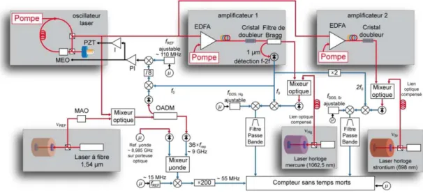
The phase locking and absolute frequency measurement chain of the fiber-based optical frequency comb are described in Fig. 1.3. Part of the optical power from the femtosecond laser is filtered with an Optical Add and Drop Module (OADM - an interferometric narrow-band filter from the optical telecommunication technology) centered at 1.54 µm. The narrow band-passed component is combined with an ultra-stable laser at the same wavelength (which is the reference oscillator for the LNE-SYRTE/LPL long distance frequency reference transfer via optical link [29]). After RF filtering, frequency division by a factor 8, and mixing with a fixed frequency reference (generated by a computer controlled DDS - Direct Digital synthesizer), the beat-note signal provides the error signal of the optical frequency comb phase-locking process. With a proportional plus multiple cascaded integrator corrector, this signal is applied to the intra-cavity electro-optic crystal of the femtosecond laser (for Fourier frequencies >5 kHz) and the piezo-electric actuator that tunes its cavity length (Fourier frequencies <5 kHz). When the loop is on, the optical frequency comb is phase-locked to the 1.54 µm reference and reaches the narrow-linewidth regime. The part of the spectrum that is not filtered by the OADM (approx. 70 mW) is fully used to illuminate a fast and highly linear InGaAs photo-detector (DSC40S HLPD by Discovery Semiconductor Inc.) which generates RF components at the repetition rate and its harmonics.
Figure 1.3: Schematics of the setup of the Er-doped fiber based optical frequency comb currently used at LNE-SYRTE for optical frequency measurements.
Another part of the femtosecond laser output is send to an Erbium-doped Fiber Amplifier (EDFA) followed by a Highly Non Linear Fiber (HNLF) which broadens the spectrum to one octave (from 1 µm to 2 µm). A Periodically Poled Lithium Niobate
(PPLN) doubling Crystal in waveguide geometry, followed by a photodetection of the beatnote between the part of the spectrum near 2 µm that is frequency doubled and that near 1 µm. This beatnote gives the f0 signal. Furthermore, part of the light obtained near 1 µm is also used to generate the optical beat-note of the comb with the 1062.5 nm ultra-stable laser which, after frequency quadrupling, is used to probe the clock transition of the neutral mercury optical frequency standard experiment. Finally, a part of the femtosecond laser output is sent to a second EDFA followed by a highly non-linear fiber and a frequency doubler that provides some comb modes near 698 nm. This last system allows the generation of an optical beatnote with the 698 nm ultra-stable laser that is the probe for the clock transition on the two Strontium optical frequency standards developed at LNE-SYRTE. After removing the f0 signal (or 2 × f0 in the case of the 698 nm beat-note), the 1062.5 nm and 698 nm signals are narrow-linewidth (typically <1 Hz) and are therefore easily filtered and subsequently amplified to have their frequencies measured with a dead-time-free, synchronous multi channel RF frequency counter 5, referenced to the primary frequency standards of the laboratory. The general setup schematics for the Er-doped fiber-based optical frequency comb at LNE-SYRTE which is used primarily for optical frequency measurement is represented on figure 1.3
1.2.3 Measuring the repetition rate
It is, of course, necessary to measure accurately and continuously the repetition rate of the optical frequency comb against primary frequency standards. This allows to deduce from the various frequencies of the optical beat-notes the absolute optical frequencies being measured, as well as that of the optical frequency reference onto which the comb is phase-locked. To do so, we use the higher harmonics of frep that are produced by the fast InGaAs or GaAs photo-detector (depending on the laser, Er-doped fiber in the first case and Titanium sapphire in the second case). With narrow microwave bandpass filters, we isolate, for the Titanium Sapphire based system, the twelfth harmonic of frep whose frequency is close to 9.2 GHz and mix it with an exact microwave reference at 9.185 GHz derived from the primary frequency reference of the laboratory. The resulting beat-note, whose frequency is close to 15 MHz, is then mixed with a RF signal that is also exact (i.e. derived from primary frequency references) but tunable (it is produced with a computer controlled DDS), so as to obtain a frequency very close to 275 kHz (to within 1 Hz). This signal near 275 kHz is then multiplied by 200 to reach a frequency of approximately 55 MHz which is measured by the dead-time-free synchronous multi-channel RF frequency counter. The frequency multiplication step is necessary in order to use the counter as best as its performance allows. As a matter of fact, this device exhibits a frequency resolution of 1 mHz at 1 s measuring time which would correspond to a resolution of only 10−13on the measurement of the harmonic 12 × f
rep, which is much less than the available stability of the frequency reference available at LNE-SYRTE. The multiplication step allows to measure in 1 s the 55 MHz frequency signal with a 1 mHz resolution, which is equivalent to measuring the 275 kHz signal with a “virtual” resolution of 5 µHz (at 1 s measuring time). Compared to the carrier at 9.2 GHz, this
corresponds to a resolution of 5.4 × 10⁻¹⁶ which is compatible with the stability of the 9.185 GHz microwave reference. Indeed, this resolution is better than the expected stability (at a few 10−15) of the microwave reference that is distributed throughout the LNE-SYRTE laboratory and therefore doesn’t represent a limitation to the optics-to-microwave frequency comparison in the laboratory. For the Er-doped fiber -based optical frequency combs, the setup is similar, except that the thirty-sixth harmonic of frep is used, and that the mixing is realized with first a fixed and exact reference at 8.985 GHz then a tunable (and exact) reference near 15 MHz to obtain a signal with a frequency very close to 275 kHz
1.2.4 Determining the index of the comb mode
In order to measure the absolute optical frequency, one needs also to identify unequiv-ocally the index N of the optical frequency comb that realizes the beat-note with the cw laser to measure, as well as the various signs + or - in the arithmetic formulas that gives the optical frequency νcw from the beat-note frequency and the repetition rate fre-quency. The frequency of the optical carrier νREF onto which the comb is phase-locked is given by the relationship:
νREF = NREF× frep+ 8 × signREF× fREF (1.3) Thus phase-locked to an optical cw reference, the comb allows to also measure other optical frequency references ν(i)
cw by isolating their beat-note signals against the nearest mode of the comb, and then mix it with f0to remove this parameter from the equations: νcw(i)= Ncw(i)frep+sign(i)× fbeat(i) (1.4) (note that equation 1.4 also holds for νREF = νcw(0) by defining fbeat(0) = 8 × fREF and sign(0)=sign
REF).
Three complementary methods allow to determine the N(i)
cw integers and the sign(i) quantities if the optical and microwave reference that are compared are sufficiently stable and/or previously known.
If the optical frequency to measure is known beforehand with an inaccuracy suffi-ciently small compared to the repetition rate frep, the first method simply consists in direct identification. Indeed, in this case, a single integer N(i)
cw, and only one sign before fbeat(i) are compatible with the equation 1.4, which naturally solves the indetermination. This is the case, for example for the ultra-stable lasers at 698 nm and 1062.5 nm at LNE-SYRTE (after their respective frequencies have been determined with other methods at least once), whose frequencies do not change by more than 1.5 MHz per year, i.e. more than two orders of magnitude lower than the repetition rate of the Titanium-Sapphire-based (approx. 767 MHz) and Erbium-doped fiber-Titanium-Sapphire-based (approx. 250 MHz) optical frequency combs.
The optical frequency drifts or the experimental tunability of other lasers in the laboratory can make the a priori uncertainty of the optical frequency too large, in which case other methods need to be used. First, the quantities sign(i)are generally quite easy to determine by opening the phase-lock loop which sets up equation 1.3 and scanning
slightly fREF while observing the direction in which the corresponding fbeat(i) signals are moving. To determine N(i)
cw, a possible method consists in realizing two successive comparisons between the optical frequency to determine and the microwave reference by using two different repetition rates frep,1 and frep,2. By measuring the frequency of the beat-note between ν(i)
cw and the mode Ncw(i) of the comb, and then with the mode Ncw(i)+ M, where M is an integer easily deduced from the scrolling of the spectral lines when going from frep,1 to frep,2. Thus, we can get Ncw(i) from the relationship:
N = M frep,1 frep,2− frep,1 +
sign(i) 2 × f
(i)
beat,2− sign(i)1 × f (i) beat,1
frep,2− frep,1 (1.5) In most cases, the stability of these two measurements (limited by that of the optical and microwave frequency reference), leads to an uncertainty much lower than 1 in 1.5 (note that increasing M reduces proportionally the stability requirement). The only hypothesis necessary for this method to succeed is that the drift of the optical frequency to determine is much smaller than frep,2− frep,1. This condition is easily fulfilled in the laboratory, where the frequency drifts of the laser to measure rarely exceed a few tens Hz per second.
Finally, by looking at equations 1.3 and 1.4, one can see that the factors N can be interpreted as the sensitivity of the relevant optical frequency to changes in frep. The third method, that we use regularly and have completely automatized, consists in inducing voluntarily a change in frep while keeping the phase-lock loop that imposes relation 1.3 closed. This is done by shifting by ∆ the value of fREFslightly (∆=1.8 MHz in practice, a value limited essentially by two fixed narrow-band filters used to isolate the various beat-notes), which must be done by ramping it continuously (to prevent failure of the phase-lock-loop 1.3, the ramping needs to be slow compared to the bandwidth of the phase-lock loop). By averaging (after the ramping) for a certain time, we obtain a repetition rate frequency value frep,+ with a given resolution. If fREF and frep vary in the same direction, then signREF = −1 (and +1 in the other case). A second ramping of fREF down by −2∆ and second averaging provides a symmetric measurement of frep,−. The value of NREF is obtained by the relation:
NREF= ⌊sign REF× 2 × 8 × ∆ frep,+− frep,− ⌉ (1.6) where the ⌊⌉ operator denotes the “round to nearest integer” function.
For ∆=1.8 MHz, frep ≃ 250 MHz, and NREF ≃ 8 × 10⁵ (hence νREF ≃ 200 THz,
ie 1.5 µm wavelength), a stability at the 10−15 level for the measurement of f
rep,+ and frep,− is sufficient to reach a resolution much better than 1 on NREF (as calculated by equation 1.6). At LNE-SYRTE, the very high stability of the microwave frequency reference distribution system allow this level to be reached in typically 8 s averaging, provided that the measurement at 8 s is dominated by, at most, flicker frequency noise process and not higher order processes which would prevent the Allan deviation of the measurement to average down (with longer averaging times) like, in particular, linear drifts.
In practice, it is very often the case that optical frequency references exhibit linear drifts of a few Hz per second that may prevent reaching a sufficiently high resolution on the measurement of the repetition rate. This issue is however easily solved, as this linear drift is not a stochastic process on the considered time scale, by measuring this drift and modifying equation 1.6 to take it into account. Specifically, if during the two averaging periods, both the average values of frep,+ and frep,− are measured, but also their first derivative with time f′
rep,+ and frep,−′ and the average time of the two measurements t+ and t−, the equation 1.6 is modified into :
NREF = ⌊ signREF× 2 × 8 × ∆ (frep,+− frep,−) − (t+− t−) × (f ′ rep,++ frep,−′ )/2 ⌉ (1.7) Such a way of taking linear drift into account could be further pushed to higher order non-stochastic drifts (quadratic drifts and so on), but we have never experienced the necessity for it at LNE-SYRTE.
The main advantage of this third method is that it can be easily automatized as it doesn’t require the opening and closing of the comb’s phase-lock-loop. However, as the value of the frequency shift ∆ that can be achieved is limited to a couple of MHz, this method requires to be able to realize an optics-to-microwave frequency comparison with a resolution of a few 10−15in a time over which the frequency drifts remains predictable (as for linear drift for example), ie a few seconds or minutes. This method is easy to implement only in an institution where microwave frequency reference with an intrinsic stability in the 10−15 range over these time constant is available (a cryogenic sapphire oscillator frequency locked on a H-maser for example).
Finally, this last method is also applicable for determining the integers N(i) cw, as a shift in the repetition rate ∆frepinduces a shift of fbeat(i) whose sign and amplitude allow to determine sign(i) and N(i)
cw.
1.3 Overview of my work on optical frequency
measure-ments
At NIST, I was involved in the work that led to the first demonstration of a neutral atom optical clock with an accuracy near 1 × 10⁻¹⁶ in the context of a collaboration between the team at JILA lead by Jun Ye and the team at NIST led by Leo Hollberg, Chris Oates and Scott Diddams. My central contribution was on the development of a robust atomic frequency standard based on neutral Calcium using a Ramsey-Bordé interferometric interrogation scheme. Although this frequency standard setup is relatively old in its design, and its performance in absolute accuracy is modest, its most prominent quality is its robustness, ease-of use, and good short term (up to a few hundred seconds) stability. Typically, after my few years at NIST, this setup was able to operate continuously for days and weeks with minimal human supervision and provide long term stability as low as 3 × 10⁻¹⁶ at 200 s averaging time.
The robustness of the Ca clock comes primarily from the low number of lasers used to operate it as only two lasers systems are used. One ultra-stable laser at 657 nm
is used to probe the clock transition 1S
0(4s2)(m = 0) −3P1(4s4p)(m = 0) transition of cold Ca atoms. The natural linewidth of this transition is 400 Hz, which is quite large compared to modern state-of-the-art optical lattice clocks (which typically use effective linewidths about 1 Hz), but sufficient to provide a stability of the clock near 2 × 10⁻¹⁵
× τ−1/2 where τ is the integrating time. This laser is an extended cavity diode laser frequency locked, with the Pound-Drever-Hall (PDH) technique on a high finesse ultra-stable Fabry-Perot cavity. The phase sidebands for realizing the PDH are realized with an EOM (finely aligned to minimize residual amplitude modulation). This master clock laser injection locks a similar diode laser (although not in an extended cavity configuration) that provides (after switching and frequency shifting AOMs) 10 mW of power on the atoms. A second laser is used for laser cooling (Zeeman slower and magneto-optical trap) the atoms down to 1 mK temperature, using the 1S
0(4s2) −1 P1(4s4p) transition at 423 nm. This cooling transition has a natural linewidth of 34 MHz, which, combined with the absence of sub-Doppler cooling effect due to lack of fine structure, prevents reaching sub-mK temperatures but still allows very fast and efficient cooling. This laser is a 846 nm extended cavity diode laser frequency locked (PDH) on a highly stable Fabry-Pérot cavity and frequency doubled in a periodically-poled lithium niobate (PPLN) crystal in a resonant bow-tie cavity (also frequency locked to the input laser with the PDH technique). As these frequency locks have much less stringent requirements than that of the clock laser, the PDH sidebands (identical for both locks) are simply realized by modulating the current driving the diode laser (which has the drawback of producing substantial residual amplitude modulation -RAM-, whose effect on the lock is, however, much smaller than the natural linewidth of the cooling transition). All lasers can be switched by single-pass AOMs before reaching the atoms, and the offset between the part of the 657 nm laser that probes the atoms and that which is used to frequency-lock in on the reference cavity is controlled by a DDS. The cfrequency-lock transition probing uses the Ramsey-Bordé method on the freely expanding atoms. The complete laser cooling cycle and frequency-lock loop is controlled by a micro-controller which drives the switches and DDS necessary to operate the full system. The full cycle duration is 5 ms, including 3 ms laser cooling (MOT) of the atoms. An important aspect of the Ca clock is that its cycle is very short, which actually allows recapturing of the atoms from the previous cycle during the laser cooling phase. This is an essential process for allowing such a small cooling cycle (90 percent of the atoms are actually recycled for the next cycle, the Zeeman-slowed newly captured atoms making the extra 10 percent in a stable cyclo-stationary regime). A total of 6 × 10⁷ atoms are laser cooled in the MOT, over which only 20 percent are used in the Ramsey-Bordé interferometric process to produce a clock error signal. This loss of efficient atoms is due to the finite available optical power at 657 nm, as the duration of the π and π/2 pulses in the Ramsey-Bordé interferometer is inversely proportional to the light intensity and the width of the velocity class that is resonant with these pulses is inversely proportional to this duration. In practice the parameters of the Ca clock were all optimized for the highest stability and not for absolute accuracy. In particular, the width of the Ramsey-Bordé beams are identical to that of the MOT, which maximizes the amplitude of the clock signal for a given optical power but renders the experiment more sensitive to residual wavefront curvatures and drifts in the atomic velocity and density distributions.
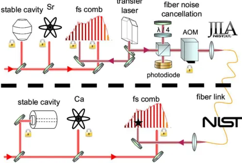
This device was used as a reference oscillator to evaluate the systematic errors of a state-of-the-art lattice-trapped neutral Strontium clock at JILA, by use of a 4-km long optical fiber link operating at 1064 nm wavelength and two optical frequency combs (one at JILA and one at NIST) connecting this optical fiber link to the 657 nm (Ca clock at NIST) and 698 nm (Sr clock at JILA) ultra-stable clock lasers (see figure 1.4). By averaging many data points, each of them corresponding to an integration over 100 s
Figure 1.4: Schematic of the setup for the comparison between the neutral calcium clock at NIST at the lattice-trapped neutral. The robustness and ease-of-use of the Ca clock allows to use it as a local oscillator of high stability to evaluate the systematic errors of the remote Sr clock.
(corresponding to a ≃ 3 × 10⁻¹⁶ stability of the comparison between the JILA Sr clock and the NIST Ca clock), the various systematic errors of the Sr optical lattice clock were studied with a resolution below 1 × 10⁻¹⁶, leading to a total budget uncertainty of 1.5×10⁻¹⁶, i.e. lower than the best existing microwave fountain clocks. This experiment was reported in Science [9].
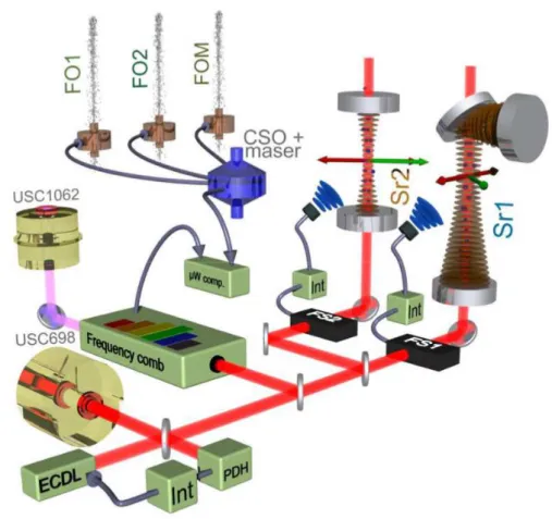
Although these NIST/JILA experiments demonstrated for the first time absolute accuracy of an optical lattice clock near 10−16, they didn’t provide an actual optical frequency measurement of the Strontium clock transition at this level and didn’t realize a link to primary frequency standards. At LNE-SYRTE a few years later, I was took part in such an experiment, which was involving the absolute frequency comparison be-tween two Strontium optical lattice clocks and the three atomic fountain clocks of the laboratory (see fig 1.5). This absolute frequency measurement campaign built upon the collective work of many LNE-SYRTE projects over decades, and provides a firmly estab-lished link between optical clocks and microwave clocks that enables a future redefinition of the SI second in terms of optical frequency cycles, (instead of the current microwave based definition). This work was recently reported in Nature Communications [12]. It
Figure 1.5: Schematics of the setup for the absolute frequency measurement of the Stron-tium lattice clocks at LNE-SYRTE vs. the laboratory’s primary frequency references (fountain clocks).
exhibits a total accuracy budget for the Strontium clocks of 1.1×10⁻¹⁶, and an accuracy of the Sr clock transition measurement set by that of the combined microwave fountain clocks at 3.1 × 10⁻¹⁶ .
The dominant term of the accuracy budgets of these two optical clocks is the so-called black-body radiation shift. This effect arises from the emission of incoherent radiation from the atoms’ experimental environment (which is near room temperature). Indeed, the blackbody radiation spectrum at 300 K is broadband and centered at 9.7 µm (as is well known from the Wien law). This radiation couples to the atomic transitions to shift the energy levels, including the ground and excited state of the clock transition. This results in a fixed frequency offset between the zero-temperature frequency and the measured frequency, which depends on the actual temperature environment expe-rienced by the atoms. The temperature of the apparatus surrounding the atoms, and most particularly the gradients are difficult to know with an accuracy much better than a degree, which produces an accuracy limit of the black-body radiation correction (near 0.8 × 10⁻¹⁶ for JILA and SYRTE Sr clocks). To decrease this effect, a possibility is to design carefully controlled thermal enclosures for the atoms, or even cryogenic