HAL Id: hal-02485675
https://hal.archives-ouvertes.fr/hal-02485675
Submitted on 20 Feb 2020
HAL is a multi-disciplinary open access
archive for the deposit and dissemination of
sci-entific research documents, whether they are
pub-lished or not. The documents may come from
teaching and research institutions in France or
abroad, or from public or private research centers.
L’archive ouverte pluridisciplinaire HAL, est
destinée au dépôt et à la diffusion de documents
scientifiques de niveau recherche, publiés ou non,
émanant des établissements d’enseignement et de
recherche français ou étrangers, des laboratoires
publics ou privés.
A NEW SPIRAL ANTENNA FOR PASSIVE UHF
RFID TAG ON DIFFERENT SUBSTRATES
Juvenal Alarcon, Thibaut Deleruyelle, Philippe Pannier, Matthieu Egels
To cite this version:
Juvenal Alarcon, Thibaut Deleruyelle, Philippe Pannier, Matthieu Egels. A NEW SPIRAL
AN-TENNA FOR PASSIVE UHF RFID TAG ON DIFFERENT SUBSTRATES. UECAP 2010, Apr
2010, barcelone, Spain. �hal-02485675�
A NEW SPIRAL ANTENNA FOR PASSIVE UHF
RFID TAG ON DIFFERENT SUBSTRATES
Juvenal Alarcón, Thibaut Deleruyelle, Philippe Pannier, Matthieu Egels
Institut Matériaux Microéléctronique Nanosciences de Provence IM2NP (UMR6242) IMT Technopôle Château Gombert, 38 rue Joliot Curie 13451 Marseille Cedex 20, France
{juvenal.alarcon, thibaut.deleruyelle, philippe.pannier, matthieu.egels}@im2np.fr
Abstract— This work presents the design of an antenna for UHF
RFID tags for supply and retail market working on different substrates. This antenna is based on the principle of broadband and frequency independent antenna like spiral antenna, which in free space simulation has a reflection coefficient less than –7.5 dB over US UHF RFID frequency band. Material's effects on impedance matching and reading range of the proposed antenna have been investigated in simulation and experimentally. All simulations were performed using a simulator based on a finite element method like Ansoft HFSS. Prototypes were measured into an anechoic chamber.
I. INTRODUCTION
RFID in (860-960MHz) UHF frequency band is growing thanks to automatic identification. It renders a more effective tracking and supply chain management. Some advantages of RFID systems are: read range, non line of sight, multiple data read/write, memory size and data storage [1].
Today, in order to design UHF antennas for supply chain market, it’s very important to have three key points in mind. The first one is production cost reduction. The goal is to achieve the lowest price for the RFID label. The second one concerns the effects of substrate materials on which the tag is attached. In this case the parameters of antenna, such as input impedance, radiation pattern, radiation efficiency, and operating frequency can change. As a consequence a reduction of reading range occurs. Finally, the utilization of same tag in different countries must be considered. Then the antenna will be broadband. This allows the simplest traceability with only one passive UHF RFID tag for products that follows in a supply chain the UHF RFID regulations in various countries.
This paper presents the design of a new antenna for passive UHF RFID tags that works over different substrates. This antenna was matched using an inductive coupling at center of UHF RFID frequency band 860-960MHz.
II. ANTENNADESIGN
This new passive UHF RFID tag, is composed of two elements. The first one is a small loop antenna of 0.12λ called “primary antenna” on which the RFID chip is mounted. The second one is a radiator element called “secondary antenna” that is a broadband antenna like truncated spiral antenna [2]. The “secondary antenna” shape’s is a spiral defined in (eq. 1), and also presents a tip loaded shape in order to make a shorter antenna [3]. The center of “secondary antenna” has a “U”
shape in order to make the inductive coupling between the “secondary antenna” and “primary antenna”.
( )
θ
r
.e
θ.
cos
θ
X
=
Y
( )
θ
=
r
.e
θ.
sin
θ
(1) In addition, with a loop antenna separated from the radiator element, the realization of prototypes becomes easier. Fig. 1 shows the antenna shape and its size.Fig. 1 Structure and dimensions of proposed tag.
The inlay’s layer structure is shown in Fig. 2. For antenna simulation, the tag prototype has been modelled employing six layers. The radiator element has been designed on layer one and on layer five the small loop antenna where the UHF RFID chip has been mounted. The others layers represent the antenna substrate. The electrical characteristics of materials are exposed in table 1.
6 Paste 5 Aluminum 4 Paper 3 Paste 2 Aluminum 1 Paper
Fig. 2 Inlay’s layers materials.
Material εr Conductivity Thickness
Paper [4] 3.26 0 S/m 100 um Paste 3.4 0 S/m 60 um Aluminum 1 3800000 S/m 15 um
III. SIMULATION
Simulations were performed using Ansoft HFSS V.11 as 3D simulator based on a finite element method. The analyses frequency band is 860-960MHz.
In order to calculate the reflexion coefficient the following expression was used:
(
Z
ANT−
Z
CHIP)
(
Z
ANT+
Z
CHIP)
=
Γ
*(2) The orthogonal gain to plane that contains the tag is considered because it indicates the position where the tag is going to be pasted in practice. Fig. 3 shows the evolution of orthogonal gain over UHF RFID frequency band that is more than 1 dBi. 860 870 880 890 900 910 920 930 940 950 960 0.0 0.5 1.0 1.5 2.0 Ga in ( d B i) Frequency (MHz)
Fig. 3 Orthogonal gain antenna.
The reflection coefficient normalized at complex conjugate RFID chip impedance is less than –7.5 dB over all the US UHF RFID frequency band (Fig. 4).
860 870 880 890 900 910 920 930 940 950 960 -20 -15 -10 -5 0 Ref lec tion Coef fic ient (dB ) Frequency (MHz)
Fig. 4 Reflection coefficient.
Fig. 5 shows the radiation pattern at 915MHz. The half power beamwidth is around 90 deg.
-15 -10 -5 0 5 0 30 60 90 120 150 180 210 240 270 300 330 -15 -10 -5 0 5 Ga in ( d B i) Phi=0 Phi=90
Fig. 5 Radiation pattern.
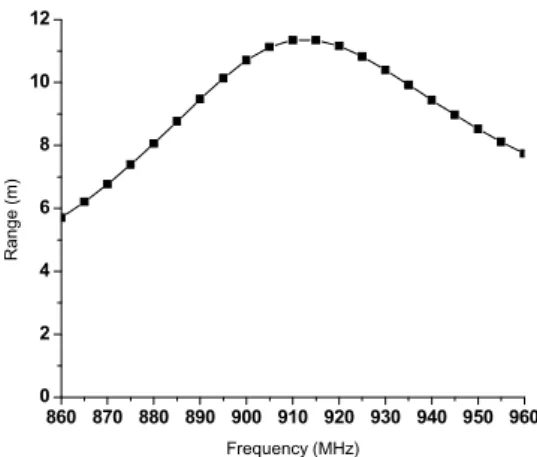
Reading range has been calculated considering the antenna’s orthogonal gain, the reflection coefficient and a 4 W EIRP as reader power.
860 870 880 890 900 910 920 930 940 950 960 0 2 4 6 8 10 12 Range (m ) Frequency (MHz)
Fig. 6 Reading range.
IV. MEASUREMENTS
Measurements have been performed into an anechoic chamber, and the maximal range has been deduced from measurements using the Friis equation, considering a 4W EIRP and a perfect polarization between reader’s and tag’s antennas.
The procedure was the following: Power transmission is decreased in order to receive the minimum tag’s response. In this state the tag works with threshold power. The minimal transmission power is called PTxMIN and the read range can be
calculate as:
(
EIRP c) (
TxMin Tx)
Mes MAXD
P
L
P
G
Range
=
.
.
.
(m) (3) With:DMes : Distance between transmission and tag antennas in
anechoic chamber (0.96 m).
PTxMin : Minimal transmission power by the reader (Watts).
GTx : Transmission antenna gain (2.15 dBi, or 1.64 linear
(e.q. 3)).
LC : Loss cable between reader and antenna.
It’s important to remark that the variations of transmission power was realized in steps of 1dB. From (e.q. 3) this step can introduce an incertitude around +13% of read range, and considering the errors like to distance reader antenna to tag (0.04 m), Loss cables (0.5 dB), reader power step (1 dB) and reader antenna gain (0.2 dB), this incertitude is around +20%.
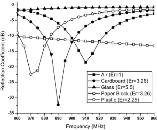
Effects of different materials on impedance matching and reading range of the proposed antenna have been investigated in simulation and in experiments. Fig. 7 shows the reflexion coefficient for different substrates in simulation.
860 870 880 890 900 910 920 930 940 950 960 -35 -30 -25 -20 -15 -10 -5 0 Ref lec tion Coef fic ient (dB ) Frequency (MHz) Air (Er=1) Cardboard (Er=3.26) Glass (Er=5.5) Paper Block (Er=3.26) Plastic (Er=2.25)
Fig. 7 Reflexion coefficient.
Table2 shows a comparative reading range for different substrates in simulation and measure. The substrate dimensions were considered as 200 mm x 200 mm x 10 mm.
Material Range (m) Simulati on Measure Free space 11.2 8.4 Card board 9.8 8.4 Plastic 8.1 7.5 Paper block of 5 cm 1.3 2.6 Glass 4.9 3.3 Glass bottle + tap
water 4.5 1.8
Table 2. Reading range for different materials
The reading range achieved has been more than 5 m over all the UHF RFID frequency band for materials with relative permittivity less than 5 (Fig.8).
860 870 880 890 900 910 920 930 940 950 960 0 1 2 3 4 5 6 7 8 9 10 11 12 13 Range (m ) Frequency (MHz) Air (Er=1) Cardboard (Er=3.26) Glass (Er=5.5) Paper Block (Er=3.26) Plastic (Er=2.25)
Fig. 8 Reading range.
V. RESULTS
The proposed new passive UHF RFID tag mounted on cardboard and plastic achieves a reading range higher than 7.5 m. Even if relative permittivity of paper block is 3.26 the reading range was 2.6 m. In this case the thickness of 5 cm introduces a bigger attenuation. On glass bottle a reading range of 3.3 m is achieved and when it contains water the reading range decreases to 1.8 m. A reason of this reduction is that the water reflects the incident wave with a phase shift of 180 deg as a metallic surface [5]. This induces a decrease of the total wave in a neighbourhood of the tag. This phenomenon causes a reduction of the reading range.
VI. CONCLUSION
An antenna for passive UHF RFID tag has been presented which is tolerant for many materials. For the antenna matching an inductive coupling was used. The tag antenna present a reflection coefficient lower than –7.5 dB over all the US UHF RFID band. This tag present a material tolerance when the objects have a relative permittivity lower than 5. The reading range is measured between 1.8 m for a glass bottle of tap water and 8.4 m for a card board object. By using two elements for tag antenna design in witch one already contains the RFID chip prototypes realisation is more easier.
REFERENCES
[1] K. Finkenzeller, “RFID Handbook”, second edition, John Wiley & Sons, Ltd., 2003, ISBN 0-470-84402-7, p.1.
[2] J.D. Kraus, “Antennas”, Mc. Graw Hill Second Edition 1997, ISBN 0-07-035422-7, p.697.
[3] D. Dobkin, “The RF in RFID Passive UHF RFID in Practice”, Elsevier 2008, ISBN: 978-0-7506-8209-1, p.321.
[4] P.V Nikitin, S. Lam, and K.V.S Rao, “Low cost silver ink RFID tag antennas”, Antennas and Propagation Society International Symposium, 2005 IEEE, p.353.
[5] D.K. Cheng , « Fields and Wave Electromagnetic », Addison-Wesley publishing company, 1983, ISBN 0-201-01239, p. 332-333.