HAL Id: tel-01743888
https://tel.archives-ouvertes.fr/tel-01743888
Submitted on 26 Mar 2018
HAL is a multi-disciplinary open access archive for the deposit and dissemination of sci-entific research documents, whether they are pub-lished or not. The documents may come from teaching and research institutions in France or abroad, or from public or private research centers.
L’archive ouverte pluridisciplinaire HAL, est destinée au dépôt et à la diffusion de documents scientifiques de niveau recherche, publiés ou non, émanant des établissements d’enseignement et de recherche français ou étrangers, des laboratoires publics ou privés.
laser cooling
Muhammad Adnan
To cite this version:
Muhammad Adnan. Experimental platform towards in-fibre atom optics and laser cooling. Optics / Photonic. Université de Limoges, 2017. English. �NNT : 2017LIMO0109�. �tel-01743888�
Université de Limoges
École Doctorale Sciences et Ingénierie pour l’Information,
Mathématiques (ED 521)
Institut de Recherche Xlim, Limoges
Thèse pour obtenir le grade de
Docteur de l’Université de Limoges
Electronique des Hautes Fréquences, Photoniques et Systèmes
Présentée et soutenue par
Muhammad Adnan
Le 18/12/2017
Thèse dirigée par Fetah BENABID et codirigée par Frédéric GEROME
JURY :
Président du jury :
Mme Valérie Madrangeas, Professeur, XLIM-Axe RF Elite, Université de Limoges. Rapporteurs :
M. Jean-Claude Garreau, Directeur de recherche, Laboratoire PhLAM, Université de Lille. M. Shau-Yu Lan, Professeur, Nanyang Technological University, Singapore.
Examinateurs :
M. Ouali Acef, Ingénieur de recherche, Observatoire de Paris, SYRTE, Paris. Mme Isabelle Zaquine, Professeur, Telecom Paris Tech, Paris-Saclay.
M. Fetah BENABID, Directeur de Recherche, XLIM-GPPMM, Université de Limoges. Mr. Frédéric GEROME, Chargé de Recherche, XLIM-GPPMM, Université de Limoges.
Experimental platform towards in-fibre atom optics and laser cooling
Muhammad Adnan | Thèse de doctorat | Université de Limoges | Page i
Acknowledgment
First of all, I would like to to pay special thankfulness, warmth and appreciations to my supervisor and mentor Dr. Fetah Benabid for his constant guidance and support throughout my thesis work and also for his patience, motivation and sharing his valuable knowledge. This would not have been possible without his timely support, guidance despite of his very busy schedule. I also thank to my co-supervisor Dr. Frederic Gerome for his guidance, valuable comments and encouragement. Dr. Foued Amrani helped me a lot for experimental data acquisition, simulations and thesis writing. I would also thank jury members Mr. Jean-Claude Garreau, Mr. Shau-Yu Lan, Mr Ouali Acef, Mme Isabelle Zaquine and Mme Valérie Madrangeas, My sincere thanks also go to Dr. Benoit Debort, Dr. Benoit. Beaudou and Dr. Jean-Marc Blondy for their knowledge sharing and their precious support which taught me sufficient experimental skills in the laboratory to conduct this research.
I would also pay thanks to Prof. Dr. Patrick Windpassinger, Institute for Physics, University of Mainz, Germany for giving me an opportunity to spend two weeks in his laboratory for secondment and whole team of QTea (Quantum sensor Technologies and applications).
Also, I thank my colleagues in GPPMM, Dr. Aurelien Benoit, Dr. Jonas H. Osorio, Jerome Alibert, Martin Maurel, Mathieu Chafer, David Kergoustin, Ximeng Zheng, Frédéric Delahaye, Alexandre Gorse, Maxime Delgrange, Thomas Billotte and Karim Frigui, all the GLO photonics team members for being in support at my experiment especially whenever we unsealed our vacuum system to do modifications inside. I will pay warm thanks to Frugier Patrick, Martin Pierre-Olivier (POM), Caperan Jean-Francois, Rainaud Ludovic, Quentin Lekiefs, Alexandre Lavigne for machining of vaccum components for my experimental set up. My special thanks go to my dearest friend Dr. Abhilash Amsanpally for his brotherly support during my stay in Limoges and to compensate my critical times with spicy and tasty curries.
Muhammad Adnan | Thèse de doctorat | Université de Limoges | Page ii
Finally I would like to thank my sister, brothers (Muhammad Imran & Atta Ullah), my nephews (Tabish, Tashfeen, Zulkifl, Zulbakht and Usairum) for their moral support during my thesis and to my friends (in Limoges) Oussama, Faten, Ines, Shaima, Oualid, Yassine, Saleh, Hamid, Jamilah, Nadia, Kausar. Very special thanks go to my late parents and late brother.
Muhammad Adnan | Thèse de doctorat | Université de Limoges | Page iii
Abstract
To cool atoms by means of laser has achieved the attraction because of their applications in quantum optics. It boosted up the technological and scientific field. It also revolutionized the functionalities frequency reference, atomic clocks, interferometer, gyroscope by their applications from laboratory environment to community users through the development of compact, stable, user-friendly and stand-alone atom-optic devices. To bring atoms from free space to nano- or micro geometries is flourishing field. This was started in the early of 90s from their confinement in capillary and now this field is matured in expertise.
The aim of this thesis is to build a versatile experimental platform for in-fiber laser cooling of Rb atoms and compact photonic device, photonic microcell (PMC) containing Rb atoms, later is not the part of this work. These photonic devices would be able to cool atoms by exciting the proper mode. These modes would be contained on far-off red detuned fundamental mode to confine and cool the atoms in longitudinal direction and blue detuned donut mode to trap them in transverse direction. We have put IC Kagome fibers with different geometries. As a whole our system has IC Kagome with different geometries with inner surface coated with materials and uncoated. Here we will focus only the nano- or micro geometries as host for cold or thermal atoms. HC-PCFs give long interactions length between gas and laser light and small modal area. After having cold or thermal atoms inside the hollow-core fibers, it is challenging to keep them inside the micro-geometries by reducing their interaction with inner glass surface. These geometries, because of their small core size, provide large surface-to-volume ratio to the atoms confined in it and needs to address the questions like the coherence relaxation dynamics and the nature and effect of the atom-surface interaction. In addition to these questions, there are challenging technological needs to be met properly such as the identification of the proper HC-PCF design so to support the appropriate spatial modes to keep these atoms confined in small core PCF, the identification of the most
Muhammad Adnan | Thèse de doctorat | Université de Limoges | Page iv
performant coating materials for the HC-PCF core inner-surface. Towards the main aim, we have successfully achieved MOT of both isotopes of Rb atoms and we characterized the temperature and number of atoms. Also we loaded thermal atoms inside hollow-core of fibers to see the difference between coated, uncoated fibers and background rubidium. Our group has vast expertise in this direction and demonstrated handful results.
Muhammad Adnan | Thèse de doctorat | Université de Limoges |
Page v
Table of Contents
CHAPTER 1COLD-ATOM OPTICS OVERVIEW ... 1
1.1 Introduction ... 2
1.1 Laser cooling and trapping of neutral atoms ... 4
1.2.1 Historical overview ... 4
1.2.2 Basic principles ... 8
1.2.2.1 Radiation pressure ... 8
1.2.2.2 Viscous force and Doppler cooling ... 9
1.2.2.3 Magnetic and optical trapping ... 11
1.2.2.4 Sisyphus cooling ... 12
1.2.2.5 Evaporative cooling ... 14
1.3 Current trends in cold atom optics ... 15
1.3.1 Cold atom based sensors ... 16
1.3.2 Miniaturized atomic optical devices ... 19
1.4 Hollow-core photonic crystal fiber enabled atom optics... 23
1.4.1 Guidance of thermal and cold atoms through optical capillary fibres ... 24
1.4.2 Hot (thermal) atoms filled HC-PCF ... 28
1.4.3 Cold atom filled HC-PCF ... 32
1.5 Laying the foundations for in-fibre laser cooling ... 36
1.6 Structure and content of the thesis ... 39
References ... 41
CHAPTER 2 HOLLOW-CORE PHOTONIC CRYSTAL FIBRES FOR ATOM-OPTIC EXPERIMENTS ... 49
2.1 Introduction ... 50
2.2 Guidance mechanism ... 53
2.2.1 Guidance mechanism of Photonic BandGap HC-PCF ... 53
2.2.2 Guidance mechanism of Kagome lattice HC-PCF ... 56
2.3 HC-PCF for cold atom and properties ... 63
2.3.1 Figure of merit ... 64
Muhammad Adnan | Thèse de doctorat | Université de Limoges |
Page vi
2.3.3 Surface induced potential ... 67
2.3.4 The modal properties ... 72
2.4 Fibre used for “in-fibre laser cooling” characterization ... 74
2.5 Summary ... 78
References ... 79
CHAPTER 3 ULTRA-HIGH VACUUM SYSTEM OF IN-FIBER LASER COOLING PLATFORM 3.1 Introduction ... 88
3.2 Ultra-high vacuum system ... 89
3.2.1 Ultra-high vacuum chamber specification requirements ... 89
3.2.2 Designing and fabrication of ultra-high vacuum chamber ... 90
3.3 Installation and assembly of the ultra-high vacuum system components ... 93
3.3.1 Atomic rubidium vapour ... 97
3.3.1.1 Rb sources ... 98
3.3.1.2 Rb loading ... 98
3.3.2 Magnetic trap design and characterization ...100
3.3.3 Fibre preparation and insertion ...105
3.4 Post processing of HC-PCF under test ...106
3.4.1 Fibre baking ... 107
3.4.2 Fibre coating ... 108
3.4.2.1 Coating materials ... 108
3.4.2.2 Coating procedure ... 108
3.4.3 Characterization of coated HC-PCF ...111
3.5 Ultra-High vacuum processing ...113
3.5.1 Vacuum pumping and baking process ...113
3.6 Rb vapor loading in coated and uncoated HC-PCF ...116
3.7 Summary ... 120
CHAPTER 4 LASER PLATFORM FOR MOT AND IN-FIBER LASER COOLING 4.1 Introduction ... 124
4.2 Description of “in-fibre laser cooling” lasers system requirements ... 124
4.3 Cooling and repumping laser system ... 128
Muhammad Adnan | Thèse de doctorat | Université de Limoges |
Page vii
4.3.2 Cooling and repumping laser ...131
4.4 Cooling and repumping laser frequency stabilization and control ... 136
4.4.1 Saturated absorption spectroscopy ...137
4.4.2 Servo locking set-up ...140
4.5 Guidance and in-fibre cooling laser systems ... 145
4.5.1 Red shifted laser ...145
4.5.2 Blue shifted laser ...146
4.6 Summary ... 147
References: ... 148
CHAPTER 5 GENERATION AND CHARACTERIZATION OF ULTRA-COLD RUBIDIUM ... 149
5.1 Introduction ... 150
5.2 Basic principle of MOT ... 151
5.3 Operation and specifications of the platform MOT ... 157
5.4 Trap loading ... 161
5.4.1 Loading the trap (experimental technique) ...162
5.4.2 Measurement of number of trapped atoms of 87Rb ...163
5.4.2.1 Laser intensities dependent...164
5.4.2.2 Magnetic field dependent ...165
5.4.2.3 Rb density dependent ...168
5.5 Temperature measurement and MOT optimization ... 170
5.5.1 Time of flight method (TOF) ...170
5.5.1.1 Experimental procedure ...171
5.5.1.2 Rb density dependent ...174
5.5.2 Release and recapture (R&R) method: ...176
5.6 Summary ... 180
References: ... 181
CHAPTER 6 SUMMARY AND FUTURE WORK ... 183
6.1 Summary ... 187
Muhammad Adnan | Thèse de doctorat | Université de Limoges |
Page viii
List of Figures
Figure 1.1 (a) Mechanism of the interaction between an atom and a photon. A photon with an energy hν equal to the difference between the two atomic energy levels and with a well-defined momentum ℏ𝒌 is absorbed to excite the atom in a higher energy level. The excited atom returns to its ground state by spontaneously emitting a photon in a random direction. (b) The net momentum exchange during a cycle of absorption and spontaneous emission. As photons are reemitted in random directions, an average of many scattering events gives an atom a net scattering force along the direction of light………...………...…5 Figure 1.2 Principle of Doppler cooling. (a) When the laser frequency is slightly red-detuned from
the atomic resonance (b) moving atom subject to damping force mechanism of the interaction between an atom and a photon. A photon with an energy hν equal to the difference between the two atomic energy levels and with a well-defined momentum ℏ𝒌 is absorbed to excite the atom in a higher state………...………...………..…....6 Figure 1.3 (a) Arrangement for 1D MOT. The horizontal dashed line represents the laser frequency seen by an atom at rest in the centre of trap. The linearly magnetic field (from anti-Helmholtz coils) produces the Zeeman shits in the atomic transition frequencies. So atoms at z>0 are closer to resonance with σ- laser beam than with σ+
beam and are therefore towards the centre of trap and same effect happens for z<0. The current in set of anti-Helmholtz coils is in opposite directions which produce the effect z=0 at middle of both coils and the laser beams intersect each other at same point. (b) When this effect is expanded for all six beams……...………...………...7 Figure 1.4 A sequence of appearance of BEC (a) Just before (b) after and (c) pure condensate [5]…………..………..8 Figure 1.5 One-dimensional velocity dependence of optical damping force for 4 different de-tunings [4]………...10 Figure 1.6 The laser cooling mechanism (known as Sisyphus cooling) in a standing wave with a spatially varying polarization. The light perturbs the energy levels of atom in periodic way because of this effect atoms travel up and down in hills and valleys (maxima and minima) in the potential energy. Atom loses kinetic energy when absorbs laser light at the top of a hill and emits a spontaneous photon of higher frequency, so that it ends up in a valley. This process provides stronger laser cooling. Thus atoms in a standing wave are cooled below the Doppler cooling limit (the lowest temperature achievable with scattering force alone) [13]………...13
Figure 1.7 (a) Schematic representation of harmonic potential in which atoms are confined (b) The atoms with above-energy escape as the height of potential is reduced. It is noteworthy that there are other schemes in cooling and manipulating atoms such as sideband and Raman cooling [26]. However, the above physical principles and techniques are the most commonly used and represent the founding physical principles of the whole field of cold atom physics. Right: Potential energy of atoms as a function of radial distance from the axis……….14 Figure 1.8 Evolution of fractional frequency uncertainties of atomic frequency standards based on microwave (Cs clocks) and optical transitions……….17 Figure 1.9 (a) The micro-fabricated atomic clock physics package based on Cs atoms (a) A CSAC physics package based on a cell containing Rb87 (b) Fractional frequency instability of
the micro-fabricated devices as a function of integration time. Squares indicate stability of Cs physics package, circles indicate stability of Rb87 physics package, and triangles
indicate stability of Rb87 cell fabricated with the beam filling technique
Muhammad Adnan | Thèse de doctorat | Université de Limoges |
Page ix
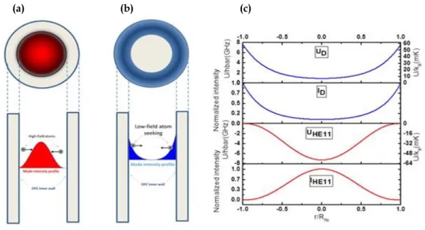
Figure 1.10 A photonic microcell [14]………..22 Figure 1.11 (a) Mode profile intensity for red-detuned (b) blue-detuned inside the hollow-core region of an OFC (c) plots of normalised intensity and their associated potential for an OFC at 780nm………....26 Figure 1.12 (a) Experimental set-up: Laser beam is coupled into the grazing incidence mode of a
hollow-core fibre. Rb atoms are guided from source chamber, where these are extracted from Rb source, to detection chamber through hollow-core fiber [73]. (b) Guided atomic flux VS laser detuning from resonance at several laser intensities [75]. (c) Experimental set-up: Cold atoms are generated using MOT in source chamber are guided in to detection chamber via hollow-core fibres of length about 24 cm which is connected in between these two chambers. (d) Detuning dependence guided atoms. At small detunings the atoms are optically pumped into the F=2 ground state (triangles). At large detunings the total flux (squares) consists to 90% of atoms in the F=1 ground state (circles) which indicates suppression of spontaneous emission during the guiding process [77]………...28 Figure 1.13 Transparency window due to EIT in the presence of 361nW control field. (inset) They achieved transparency larger than 90% when a probe scanned over 5S1/2, F = 1 to 5P1/2,
F’= 1 with a 2.65 µW control field tuned to 5S1/2, F =1 to 5P3/2, F’= 1 transition. (b) Study
on the variation of the linewidth of EIT as a function of control intensity (figures taken from [81])………30
Figure 1.14 (a) SEM image of kagome HC-PCF (b) SEM image of the core after coated with PDMS (c) Experimental set up with two lasers used one is (ECDL) probe and Ti:Saph (coupling) (d) Absorption spectra in the presence of probe only to prove that Rb is inside the hollow-core of fibre. (e) EIT is observed when probe beam of power 5nW interact with 1.6µW coupling beam in core of 30 cm long kagome HC-PCF filled with Rb. Inset (left) Zoomed peak showing the linewidth. Inset (right) Lambda energy level scheme of Rb85 (f) Coupling power of laser VS EIT height and width [66]…….30
Figure 1.15 (a) Side view of splice: An HC-PCF spliced with single mode fibre (SMF) (b) End view of an HC-PCF when cleaved at the junction of the splice. (c) Shows clearly the preservation of structure when cleaved few mm from splice. Fibre is same as in (a) and (b). (d) Photograph of a 5-m-long hydrogen-filled HC-PCF gas cell. Its size is comparable with matchstick (e) frequency stabilization set up (f) small circle on red curve shows the locking point of P9 absorption line of acetylene (g) left-hand side part of trace: is frequency fluctuation when laser is free running- right-hand side part of trace: when laser is locked, exhibits maximum r.m.s frequency deviation of 310 KHz (figures taken from [14])………..31 Figure 1.16 (A) Experimental set up. (B) Atomic waveguide based on hollow beam (figures taken
from [84-85])………...………...32 Figure 1.17 (a) Experimental set up showing the position of 3D- MOT, which is created at the one face of PBG HC-PCF. The position of trapped atoms is changed by changing the position of additional magnetic field. The atoms are detected by fluorescence imaging with a retro-reflected laser beams and photons are collected, with an intensified CCD camera, after guiding therough the fibre. Observed atomic flux, after loading into the fibre as a function of time (b) A peak flux of (1.2±0.1) X105 atoms s-1 can be seen when
atoms are loaded directly from optical molasses and this flux is extended over 50 ms. (c) The peak flux remains unchanged but a constant flux of 1.5X10⁴ atoms is
maintained for more than 150 ms by creating an auxiliary reservoir dipole trap at the fibre input. (d) Schematic of potential to guide the cold atoms: from their preparation (right side) and exit on other side. [86])..……….…33
Figure 1.18 (Upper left) (a) MOT atoms are -1.6 mm away from the face of fibre. (b) The atoms are transported in to HC-PCF by tuning the frequency of the lattice laser (c) Protocol for atomic expansion. (d) Atoms in HC-PCF are confined axially and radially by the optical lattice preventing the atoms to interact with fibre-core wall (e) SEM image of kagome fibre (f) Far-field mode profile. (Upper right) The blue region indicates the fibre. After cooling atoms are loaded at z=0 in 32mm long fibre. Due to increase in the collision with residual gases the lifetime inside the fibre (filled circles) decreases
Muhammad Adnan | Thèse de doctorat | Université de Limoges |
Page x
towards the middle of the fibre. The lifetime determined by them is about ~ 347 ms. (lower left) Absorption spectra with and without atomic expansion over lattice sites (inset) are displayed by red and blue symbols respectively. Distribution of atoms over lattice site corresponding to mean atom occupation of m’ = 0.45 and m’ = 1.7. (lower right) Spectral width: The shift of spectrum and atomic number-dependent broadening are suppressed by applying a lattice-expansion protocol [16]…………...35 Figure 1.19 Schematic of the experimental platform for in-fibre laser cooling. Laser 1 is a frequency-stabilized laser for cooling and re-pumping for both isotopes (Rb85-Rb87),
laser 2 is tunable Red-detuned laser for dipole res-detuned trapping and guidance of atoms and laser 3 is tuneable Blue-detuned laser for dipole blue-detuned trapping and guidance………...………..………...…...38 Figure 2.1 Summary of historical development of HC-PCF technology based on PBG and IC
guidance. The area in gray color in the graph represents the years of theoretical developments from PBG guidance to first HC-PCF invention. The blue area represents development of HC-PCF based on PBG (in solid line borders) and IC (dashed boarders) [9]……….52
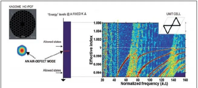
Figure 2.2 (I) (a) Density of photonic states (DOPS) calculated for a cladding structure with a 91.9% air-filling fraction (a). Apex, (c) strut and (d) airy modes which define the bandgap are highlighted by red, blue and green dash lines respectively [15].(II) Photonic Tight-Binding model: (a) Dispersion curve of fundamental and second higher-order modes of a silica rod. Here the modes below the air-line are ignored (b) Dispersion diagram of an array of silica rods. (c) Dispersion diagram of an array of silica rods after an appropriately transformation [15]………...………..54 Figure 2.3 Density of optical photonic states calculated for a kagome lattice HC-PCF……...…..57
Figure 2.4 (a) Core guiding mode of Kagome lattice HC-PCF, (b) Fast oscillating cladding mode of Kagome HC-PCF. Middle image is the intensity plot of (a) core mode (b) cladding modes along length Λ identified by dashed line [8]……….57 Figure 2.5 Illustration of the enhanced IC guidance by using hypocycloid core contour. (a)
Idealized traditional kagome HC-PCF, core mode overlap with low azimuthal number cladding modes, and 2D profile distribution of core mode field which diameter is related to core boundary. (b) The same for a hypocycloidal kagome HC-PCF [22]………59 Figure 2.6 (a) Computed confinement loss evolution of kagome-lattice HC-PCF with the varying
arc curvatures (b = 0, 0.2, 0.5, 1 and 1.5). The dashed lines are added for eye-guidance. (b) The fiber structure transverse profile for the different b values. (c) Evolution with b of the transmission loss figures for 1000 nm (joined solid squares) and for 500 nm (joined open circles) wavelengths [21]………60
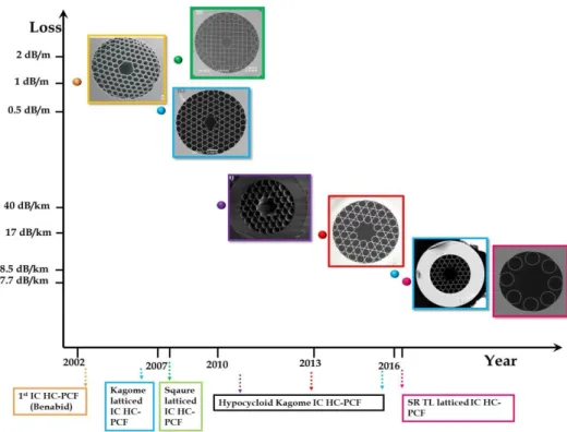
Figure 2.7 Loss spectra evolution versus the wavelength for several fabricated IC kagome lattice HC-PCFs with different silica strut thickness. The SEM images of the cross section of the fibers and the geometrical parameters are added………..61 Figure 2.8 Summary of the historical development of IC HC-PCFs and their respective loss figures with
SEM Images………..……62 Figure 2.9 Comparison of FOM for capillary and different transmission loss HC-PCF [22]………65 Figure 2.10 Spectral broadening from the transit time (dash line) and atom-wall collisions of core
radius (solid line) dependency……….…66 Figure 2.11 Surface-atom potential for the case of Rb ground state and for different ranges of the atom-surface distance. The black curve corresponds to 6-12 type potential (equation 2-6) with the parameters taken from reference [58]. The red curve corresponds to the potential of equation 5-3 with the parameters taken from reference [61]………...68 Figure 2.12 Surface-atom potential profile as experienced by a Rb atom inside a 60µm core
Muhammad Adnan | Thèse de doctorat | Université de Limoges |
Page xi
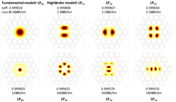
diameter of HC-PCF for the D2 transition ground (red curve) and excited state (blue curve)………...71 Figure 2.13 Examples of the first guided modes calculated in a hypocycloid core Kagome lattice
HC-PCF………72 Figure 2.14 (a) Intensity radial profile for the HE11 or LP01 ( red curve) and LP31 mode ( blue curve)
in a 46 m core diameter 7 cell hypocycloid core contour Kagome HC-PCF. (b) the potential radial profile deduced from a red detuned HE11 mode ( red curve) and blue
detuned LP31 mode. Here the intensities and detuning values are the same as in Fig.
1.13………..……….73
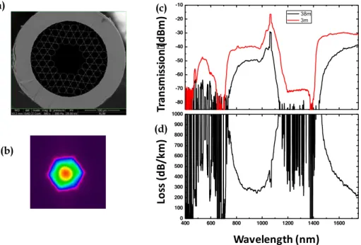
Figure 2.15 Optical characterizations of the 1 cell kagome lattice HC-PCF used for experiments……….…76 Figure 2.16 Optical characterizations of the 7 cell kagome lattice HC-PCF used for experiments……….76 Figure 2.17 Optical characterizations of the 19 cell kagome lattice HC-PCF used for experiments……….77 Figure 2.18 Optical characterizations of the 9 tubular lattice HC-PCF used for experiments…... ….77
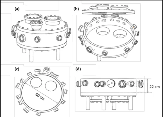
Figure 3.1 Drawing of chamber in different positions: (a) when the lid is closed (as on the laser table), (b) and when the lid is partially opened. (c) Open lid top-inside view. Diameter of chamber is 60 cm (d) and side view (in real position on the laser table). Height of the chamber is 22 cm………..…..92 Figure 3.2 Position of breadboard, fibres and anti-Helmholtz coils inside the UHV
chamber………...………..93 Figure 3.3 (a) and (b) are solid work drawings of UHV chamber showing the position of laser
beams for MOT, ion and turbo-molecular pumps………. 93 Figure 3.4 The star-cross method that is used for tightening viewports to a vacuum
system... ...95 Figure 3.5 Pictures of the top-lid opening, aligning and closing: (a) when the lid is open
(alignment of wire seal copper gasket with the proper grove on lower portion of lid). (b) Lid is held by crane (while working on in-vacuum components). (c) Tightening the screws after sealing the platform……….……...…96 Figure 3.6 Different viewing angles of Ultra-High-Vacuum system (on laser table)….………97 Figure 3.7 (a) Setting HC-PCFs under test on the holder. (b) Zoom in the fibres holder, kapton
coated copper wire (used for internal wiring for dispensers) and anti-Helmholtz coils. (c) Zoom in the Rb dispenser and the breadboard with M6 threads ..………...97 Figure 3.8 (a) Rubidium dispenser (Rb/NF/14/50FT10). (b) Rb vapor density VS temperature.
The density of Rb at room temperature is negligible. The pressure of 1 µbar and 1 mbar are obtained at temperature of 117 °C and 287 °C respectively [11]. (c) Top view and side view of the connection and position of Rb dispensers. It is connected with homemade copper connector at the centre of chamber, few centimetres away from the MOT region by using UH vacuum compatible kapton coated wires………99 Figure 3.9 Rb dispenser is glowing when current above threshold passes through it (A).
Fluorescence can be seen, when denser vapors of Rb interact with on-resonance laser beam coupled via one of the view port (c & d)……..………..………...100 Figure 3.10 The temperature of dispenser as a function of applied current to the dispenser for
different environmental temperature [7]………..…100 Figure 3.11 (a) Schematic of Zeeman splitting and magnetic gradient trapping. (Middle) The 85Rb
and 87Rb 52S1/2 ground state energy (and the resulting hyperfine structure) is shown
as a function of an external magnetic field. The levels are grouped according to F in the anomalous Zeeman Effect regime. (b) The hyperfine levels in the 85Rb (left) and
Muhammad Adnan | Thèse de doctorat | Université de Limoges |
Page xii
87Rb (c) involved in the D1 and D2 transitions, labelled with their F values.
……….………102 Figure 3.12 The anti-Helmholtz design……….103 Figure 3.13 (a) Image of a contour plot of ratio r between the coil radius and the distance of the
two coils. (b) Field magnitude of the quadrupole trap in the y–z–plane in Anti-Helmholtz configuration. Each contour line corresponds to a field increase of 1.5 G. (c) The magnetic field value between the coils for a current of 3 Am………..103 Figure 3.14 Home-made UH vacuum compatible pair of anti-Helmholtz coils made from 316L
stainless steel. Table 3.2: Anti-Helmholtz coils parameters………...105 Figure 3.15 Design of fibre holder………..………106 Figure 3.16 Fibre installation inside the chamber and fibre holder position on the breadboard near
the anti-Helmholtz coils………...………..106 Figure 3.17 Illustration of coating procedure of the inner core wall surface of HC-PCF. In first step,
cladding is collapsed, second step is about filling of solution and third step is for baking and coating deposition……….…….…...109 Figure 3.18 SEM images of deposition layer thickness obtained inside the HC-PCFs versus the
drying temperature………..110 Figure 3.19 SEM images of HC-PCFs uncoated with different geometries………...111 Figure 3.20 Transmission spectra of 19 cells Kagome HC-PCF. Red (solid) curve shows the
spectrum with coating and black dotted without coating (a) Sol-Gel (b) PDMS……….……....112 Figure 3.21 Evolution of the baking temperature and pressure for five days. This reflects the
procedure used to bake our chamber until to get the minimum vacuum pressure………...114 Figure 3.22 The comparison between the pressure and days took to be evacuated. Inset shows the
baking procedure followed every day………..…115 Figure 3. 23 Sequence of sealing and unsealing the UHV chamber……….………..…...115 Figure 3.24 Optical setup for the measurement of the absorption spectrum of under test fibres
inside the chamber………...116 Figure 3.25 Measured Rb D2 absorption lines of Rb vapor contained in under test Kagome
HC-PCFs (1 cell, 7 Cell, 19 Cell and tubular fibres) and vacuum chamber. In vacuum (red solid line) for reference, in PDMS coated Kagome HC-PCF (magenta solid line), in sol-gel coated Kagome HC-PCF (olive solid line) and in uncoated Kagome HC-PCF (blue solid line)………...117 Figure 3.26 Evolution of Rb absorption contrast in under test Kagome HC-PCFs (1 cell, 7 Cell and
19 Cell): Uncoated Kagome HC-PCF fibre (red dots), Sol-Gel coated Kagome HC-PCF (black dots) and PDMS coated Kagome HC-PCF (blue dots)………...…....118 Figure 4.1 Overview of the laser system setup for in fibre laser cooling
experiment………...126 Figure 4.2 Energy levels of 85Rb split from the ‘two level atom’ with fine and hyperfine levels.
The picture involved the D1 and D2 transitions, labeled with their F values. The figure is not drawn to scale but each hyperfine splitting frequency is identified, as well as the fine structure transition at 795 nm (377 THz) and 780 nm (384 THz). The hyperfine level separations are also illustrated…………..……….…129
Figure 4.3 Energy levels of 87Rb split from the ‘two level atom’ with fine and hyperfine levels.
The picture involved the D1 and D2 transitions, labeled with their F values. The figure is not drawn to scale but each hyperfine splitting frequency is identified, as well as the fine structure transition at 795 nm (377 THz) and 780 nm (384 THz). The hyperfine level separations are also illustrated………..……….129
Muhammad Adnan | Thèse de doctorat | Université de Limoges |
Page xiii
Figure 4.4 The possible cooling and re-pumping transitions for 85Rb at the left and 87Rb at the
right for MOTs and approximate wavelengths………..…………...…..131 Figure 4.6 Carrier and sidebands generated after passing through the non-linear crystal…….135 Figure 4.7 Spectra of generated sidebands at 3.036 GHz (at the left) and at 6.835 GHz (at the right)
for repumping laser for 85Rb and 87Rb respectively……….135
Figure 4.8 Spectra of generated sidebands at 3.036 GHz (at the left) and at 6.835 GHz (at the right) for repumping laser for 85Rb and 87Rb respectively………...…..135
Figure 4.9 Schematic drawing of the laser set-up with FMS locking setup (in the blue dashed box). The generation of the sideband signal for repumping (in the orange dashed box). Yellow lines are optical paths and black lines are electrical signal paths………..….136 Figure 4.10 The optical layout for saturated absorption spectroscopy………...…..137 Figure 4.11 Saturated absorption spectroscopy for both 85Rb (top) and 87Rb (down) showing the
upper ground state to hyperfine (F’) levels………..139 Figure 4.12 Optical scheme for Doppler free saturated absorption spectroscopy (left) and beam paths with components map of spectroscopy module (right)………...140 Figure 4.13 Electronic diagram of the servo locking system………..…141 Figure 4.14 Comparative frequency spectrum of the saturated absorption DC signal (blue trace) and its error signal obtained at 4 MHz (red trace) for 85Rb (upper) and 87Rb
(lower)………142 Figure 4.15 Measured Allan variance (σ) of cooling and repumping lasers locked for different time intervals (black, blue and pink), free running (red) and the fit (olive). Cooling / repumping lasers were frequency stabilized at an Allan variance of 2x10-12 for 1300
s………...…143 Figure 4.16 Measured linewidth of the dual frequency laser. (a) cooling laser, (b) repumping laser………....144 Figure 5.1 Photograph of 85Rb atoms trapped in the MOT………….……….………..161
Figure 5.2 Optical scheme for fluorescence detection. Fluorescence of MOT at equilibrium state is detected on oscilloscope……….162 Figure 5.3 Loading curves for measurement of number of atoms of Rb87 at different laser
intensities (a) 4.5mW/cm2 (b) 6.5mW/cm2 (c) 8mW/cm2(d) 10mW/cm2. While
keeping magnetic field gradient (9.6G/cm) and current for Rb source (4.5A) constant……….….164 Figure 5.4 Relationship between (a) Laser power and number of trapped atoms (b) Laser intensities and loading time………....165 Figure 5.5 Loading curves for measurement of number of atoms of Rb87 at different magnetic field gradients (a) 8.8 G/cm (b) 11.8 G/cm (c) 14.4 G/cm (d) 16.4 G/cm. While laser intensity (8mW/cm2) and current for Rb source (4.5A) are constant. The curve was fitted a function of the form equation (5.19) (red curve)………...166 Figure 5.6 Comparison between (a) magnetic field gradient and number of atoms (b) magnetic field gradient and loading time………..…166 Figure 5.7 Loading curves for measurement of number of atoms of Rb87 at different magnetic field gradients (a) 9.6 G/cm (b) 11.8 G/cm (c) 14.4 G/cm (d) 16.4 G/cm. While intensity (10mW/cm2) and current for Rb source (4.5A) are constant. The curve was fitted a function of the form equation (5.19) (red curve).………..……….167 Figure 5.8 Comparison between (a) magnetic field gradient and number of trapped atoms (b)
Muhammad Adnan | Thèse de doctorat | Université de Limoges |
Page xiv
Figure 5.9 Loading curves for measurement of number of atoms of Rb87 at different current of Rb
source (a) 3.5 A (b) 4A (c) 4.5A (d) 5A. While laser intensity (10mW/cm2) and magnetic
field gradient (9.6G/cm) are constant………..…169
Figure 5.10 Comparison between (a) Rb dispenser current and number of atoms………169 Figure 5.11 The optical scheme for time of flight measurement technique………...…172 Figure 5.12 Cloud of 87Rb in a MOT taken from side view with CCD camera and the size of screw used for the pixel size calibration………..172 Figure 5.13 Cloud expansion of MOT obtained from the recorded decay. The image of the cloud is
taken every 2 ms from an expansion time of 1 ms to 15 ms. The cloud radius is measured using the Gaussian fit………173
Figure 5.14 Measured temperature of Rb87 at different current for Rb source (a) 3.5A (b) 4A (c) 4.5A
(d) 5A. While intensity (10mW/cm2) and magnetic field gradient (9.6 G/cm) are
constant………..174 Figure 5.15 (a) Gives the comparison between the number of trapped atoms and current for Rb source (Rb density) given in Figure 5.10 (b) The comparison between temperature measured by using TOF method and different values of current for Rb source given in Figure 5.15. Both the measurements (number of atoms and temperature) were taken at same time by using same parameters. The trend in both the graphs is same.………...175 Figure 5.16 Minimum measured temperature of 87Rb by using time of flight method. The laser
intensity 4.5 mW/cm2 and magnetic field gradient of 14.4 G/cm………...175
Figure 5.17 Scheme of temperature measurement by using release and recapture technique (top). When the delay between switch-off and switch-on, the MOT is increased, the amount of atoms recaptured in the MOT becomes smaller and smaller. The reconstructed curve after collecting the number of atoms for several interval time Δt (down)……176
Figure 5.18 The optical scheme for release and recapture method………...………177 Figure 5.19 (R&R)- Measured temperature of 87Rb at different magnetic field gradients (a) 8.8
G/cm and (b) 16.4 G/cm while intensity (6.3 mW/cm2) and current for Rb source
(4.5A) are constant……….………..178 Figure 5.20 (TOF)- Measured temperature of 87Rb at different magnetic field gradients (a) 8.8
G/cm (b) 16.4 G/cm while intensity (6.3mW/cm2) and current for Rb source (4.5A)
are constant……….….….179 Figure 5.21 Temperature measurement by using (a) Time of flight method (TOF) (b) release and
Muhammad Adnan | Thèse de doctorat | Université de Limoges |
Page xv
List of Tables
Table 3.1 Conflat flange details ………;………..……...93
Table 3.2 anti-Helmholtz coils parameters……….……….….105
Table 3.3 Properties of surface coating materials ………...108
Table 3.4 Characteristics of fibres shown in figure 3.16………...111
Table 4.1 Specifications of lasers for in fibre laser cooling platform………....127
Table 4.2: Energy shift for 85Rb………...130
Table 4.3: Energy shift for 87Rb……….………..130
Muhammad Adnan | Thèse de doctorat | Université de Limoges |
Page xvi
Abbreviations
HC-PCF Hollow-Core Photonic crystal fiber
PMC Photonic MicroCell
BEC Bose-Einstein Condensate
MEMS Micro Electro Mechanical Systems
SQUID Superconducting QUantum Interference Device
OFC Optical Fiber Capillary
EIT Electromagnetically Induced Transparency
IC Inhibited Coupling
UHV Ultra-High Vacuum
TBM Tight Binding Model
DOPS Density Of Photonic States
Muhammad Adnan | Thèse de doctorat | Université de Limoges |
Page xvii
Definition of symbols
𝛽 Axial component of wavevector 𝑘 𝑐 Speed of light in a vacuum
ℎ Planck’s constant
ℏ Reduced Planck’s constant (ℎ/2𝜋) 𝑘 Wavevector, 1⁄𝜆
𝑘B Boltzmann constant
𝑘Λ Normalised frequency
Λ Fibre cladding pitch
𝜆 Wavelength mean-free-path
μ Transitional dipole moment kinematic viscosity 𝑛 Refractive index
Muhammad Adnan | Thèse de doctorat | Université de Limoges |
Muhammad Adnan | Thèse de doctorat | Université de Limoges |
Page 1
Chapter 1
Cold-atom optics overview
This chapter presents a historical review of laser cooling and trapping
of atoms and the current trends in this field with an emphasis on
atom-optics in hollow-core photonic crystal fibre (HC-PCF). After listing the
key fundamental and technological developments that led to the
emergence of the field, we highlight the basic physical principals behind
the atom motion control with lasers, which then led to atom cooling
and trapping. We then survey the current trends in cold atom. We will
emphasize on the different platforms that are currently explored for
making thermal and cold atoms in miniaturized devices, with a
particular focus on HC-PCF and its functionalized form photonic
microcell (PMC). We will then finish this chapter by describing the
motivations and the work undertaken in this thesis to address the
challenges towards the long-term goal of “in-fibre laser cooling”.
Muhammad Adnan | Thèse de doctorat | Université de Limoges |
Page 2
1.1 Introduction
Atomic cooling by laser means has been one of the most successful endeavours in atomic physics in the last thirty years, illustrated by the large number of Nobel prizes in this field [1]. Indeed, since the first theoretical proposals in the 70s [2], the field has gone from successfully demonstrating the principle of laser-induced cooling neutral atom to decreasing the temperature to the Doppler limit (i.e. the lowest temperature possible by virtue of the effect of Doppler [3]). Then to below this limit with the advent of new concepts such as Sisyphus cooling [4], and later to generate a new phase of matter, namely, Bose-Einstein Condensates (BEC) with temperature-level as low as nano-Kelvin range using evaporative cooling effect in late 80s early 90s [5]. Today, cooling atoms with laser has reached a level of maturity that BEC can be formed at below 500 picoKelvin temperature [6].
Such a progress in laser-cooling atoms was both a technological and scientific adventure and its impact is still timely. It revolutionized the optical metrology in direction of distances and dimensions, temperature, frequency and time. The potential of atomic optics revealed by the atomic interferometers [7], such as Sagnac gyroscope [8] and Mach-Zehnder interferometers [9] boost its performance compares to its optical counterparts. Physical quantities like gravity [10] and electric polarizability [11] could be measured accurately with atomic interferometers than an optical interferometer.
Today, laser-cooled atoms are used both as a technological tool in several research area and a subject of fundamental physics such as atomic clocks [12], interferometry [9] and Rydberg atoms [13] for ultra-precision sensing and quantum information. On the other hand, they are a platform to observe novel physical phenomena at very low energy scale such as phase transition to new form of matter. Laser cooling techniques are also a major tool to cool molecules or to synthesize them via photo-association.
Muhammad Adnan | Thèse de doctorat | Université de Limoges |
Page 3 Another route that is of more interest towards industrial applications use by the broader academic communities is to miniaturize the laser cooling set-up and/or to be available commercially in the form of compact atomic device. This work aligns itself with this broad and ambitious aim by exploring the feasibility of laser cooling atoms that are inside a hollow-core photonic crystal fibre (HC-PCF). Furthermore, the present work stems from both the field of cold atoms and that of photonics. This platform will be based on HC-PCF for its ability to host both gas phase media and photon within micro-meter scaled effective area and to make them interact over lengths which can be easily well over 10 orders of magnitude longer than the typical Rayleigh length. When the HC-PCF is filled with a gas-phase medium and then spliced in a hermetic and low optical loss manner to a solid optical fibre, it takes the form of what is called photonic microcell (PMC) [14]. Thus a PMC is a seemingly a standalone optical fibre that also act as a vapor cell, and has now proved to be an excellent photonic component for several fields including spectroscopy [15-16]. This work is developed with the aim to first create an experimental platform for studying and controlling cold as well as thermal atoms inside HC-PCF, and then to be used to explore the feasibility of “in-fibre laser cooling” whereby thermal atoms confined in a PMC can be cooled at any time by an appropriate modal excitation of the PMC. In this chapter, we will give a historical review on how laser cooling has been developed. Then we will provide a survey on current state-of-the-art applications in this field and list the major research trends, with an emphasis on the works related to laser cooling in compact devices or in confined geometries. In a following section, we will focus on the prior works related to the attempts of manipulation of thermal and cold atoms in hollow-core waveguides.
Muhammad Adnan | Thèse de doctorat | Université de Limoges |
Page 4
1.2 Laser cooling and trapping of neutral atoms
1.2.1 Historical overview
Manipulating atoms, molecules or particles with light has been a subject of research since Johannes Kepler in the 17th century [17] whereby the momentum
carried by a photon has already been identified as a possible means to apply a mechanical force on atoms, molecules or particles [3]. The first prediction that light exerts pressure upon any surface exposed to it was proposed in 1871 by James Clerk Maxwell. Later, in 1901, J. N. Lebedev [18] measured the movement induced by light on a suspended metallic mirror in a high vacuum. According to these early work, a planar electromagnetic wave with an average Poynting vector 〈𝑆〉 exerts a pressure P on a fully absorbing surface given by 𝑃 = 〈𝑆〉 𝑐⁄ , with c being the speed of light. Nicholas and Hull [19] confirmed the first quantitative proof of Maxwell's electromagnetic theory in the same year. With the invention of the laser, such proposals of mechanically controlling matter with light witnessed a renewed interest and experienced a radically new outcome with atom control. The possibility of interaction between atoms and a laser standing-wave was first introduced by Letokhov in 1968 [20]. Further insights were sought by A. Ashkin [2] who developed the concept of cooling and trapping atoms using light radiation pressure in 1970. Particularly, Ashkin introduced the impact of resonant absorption and spontaneous emission (see Figure. 1.1) on the atomic translational motion, he assumed that because of random direction of spontaneous emission, the momentum of the exciting photon during absorption is communicated to the atom momentum. Later, T.W. Hansch and A.L. Schawlow [21] extended on Ashkin work to point out that atoms can be cooled (that’s the atom translational kinetic energy can be reduced by virtue of the relation between the r.m.s. thermal velocity 𝑣𝑡 and the temperature T:
Muhammad Adnan | Thèse de doctorat | Université de Limoges |
Page 5 constant and m the mass of the atom) by a laser with a frequency that is red-detuned by around half the Doppler width from the atom resonance. This cooling concept is illustrated in Figure. 1.2, and is now part of the standard techniques in laser-cooling of atoms, and is coined as Doppler cooling.
Figure 1.1: (a) Mechanism of the interaction between an atom and a photon. A photon with an energy hν equal to the difference between the two atomic energy levels and with a well-defined momentum ℏ𝒌 is absorbed to excite the atom in a higher energy level. The excited atom returns to its ground state by spontaneously emitting a photon in a random direction. (b) The net momentum exchange during a cycle of absorption and spontaneous emission. As photons are reemitted in random directions, an average of many scattering events gives an atom a net scattering force along the direction of light.
The cycle of Doppler cooling is the following: an atom moving away from the red-detuned laser, absorbs a photon of momentum ℏ𝑘 and gets excited. The frequency of the light will appear lowered out of resonance with the scattering transition, and the atoms can only lose energy and momentum by scattering of the laser light, and never gain. If the light comes from all directions, atoms will lose energy by scattering the oncoming light, while the Doppler-shift will detune any light wave traveling in the same direction as the atoms. In this way the translational temperature of the atoms can be reduced until ultimately the Doppler line width is as small as the natural line width [21].
Muhammad Adnan | Thèse de doctorat | Université de Limoges |
Page 6 The first experimental demonstration of the above principles was achieved in 1985 by Steven Chu et al. [3] who reported cooling and viscous confinement of neutral sodium atoms in three dimensions by using three orthogonal pairs of counter propagating red-detuned laser beams intersecting each other at the centre which formed the trap. In this trap, a cloud of slow atoms (optical molasses) exhibiting a density of ~106/cm 3 were confined in 0.2 cm3 volume for 0.1 sec. The lowest
measured temperature was then about ~240 µK (which is the limit set by Doppler cooling with Na). Here, atoms were not confined spatially (optical molasses), and can thus slowly drift out the cooling volume. In this seminal work of S. Chu et al. [3], the optical molasses’ atoms are confined only in velocity space but not in position space. To ensure atom’s confinement in both velocity-space and coordinate-space, the magneto optical trap (MOT) is developed and reported in 1987 by E. L. Raab and colleagues. The principle of a MOT is illustrated in Figure. 1.3 where a magnetic trapping is added to the optical trap described above by adding a spatially varying magnetic quadrupole field using a pair of anti-Helmholtz
Figure 1.2: Principle of Doppler cooling. (a) When the laser frequency is slightly red-detuned from the atomic resonance (b) moving atom subject to damping force mechanism of the interaction between an atom and a photon. A photon with an energy hν equal to the difference between the two atomic energy levels and with a well-defined momentum ℏ𝒌 is absorbed to excite the atom in a higher state.
(a)
Muhammad Adnan | Thèse de doctorat | Université de Limoges |
Page 7 coils. This causes a Zeeman shift in atom energy levels that increases with the radial distance from the centre of the trap. In turn, by virtue of Lorentz force an atom moves away from the centre of the trap feels a force that pushes it back to the centre of the trap. This confers the ability of MOT both to cool and confine atoms in velocity-space and coordinate-space. The MOT is, nowadays, the most common tool to create cold neutral atoms. In its first demonstration, Raab et al. confined and cooled down to ~0.4 K optically dense cloud of 107 neutral sodium within a volume
of ~ 0.5 mm in diameter and with a density 1011/cm3 for two minutes. They trapped
and cooled atoms with temperature less than milliKelvin with trapping and ~0.4 K deep [22].
Figure 1.3: (a) Arrangement for 1D MOT. The horizontal dashed line represents the laser frequency seen by an atom at rest in the centre of trap. The linearly magnetic field (from anti-Helmholtz coils) produces the Zeeman shits in the atomic transition frequencies. So atoms at z>0 are closer to resonance with σ- laser beam than with σ+ beam and are therefore towards the centre
of trap and same effect happens for z<0. The current in set of anti-Helmholtz coils is in opposite directions which produce the effect z=0 at middle of both coils and the laser beams intersect each other at same point. (b) When this effect is expanded for all six beams.
Another major milestone in the history of cold atoms is the achievement of cooling atoms to a temperature below the limit set by the Doppler cooling model. Indeed, in 1988 William D. Phillips and co-workers achieved a cold sodium cloud with temperature 10 times below their Doppler limited temperature, which is 240 µK [23]. It turns out that the two-level atom of the Doppler cooling model was too simple to capture all the dynamics of such laser-atom interaction. In 1989, J. Dalibard and C. Cohen-Tannoudji [4] provided the theoretical explanation of such sub-Doppler limited temperature, and whereby they demonstrated that the polarization gradient of the counter-propagating laser cooling beams alter
Muhammad Adnan | Thèse de doctorat | Université de Limoges |
Page 8 significantly the internal state of the atomic ground-state Zeeman levels (see the section below); a phenomena that was coined “Sisyphus Cooling”. The latter results concluded the exciting history of the advent of cold atoms by the award of the 1997 Nobel Prize to S. Chu, W. Philips and C. Cohen-Tannoudji [1]. Furthermore, Sisyphus cooling opened a new chapter of cold atoms by allowing the achievement of temperature ranges below the critical temperature, 𝑇𝑐 = 0.089 (ℎ2⁄𝑚𝑘𝐵)𝑛2/3 [5],
for a phase transition to BEC. Here, n is the density of the cold atoms. The first demonstration of BEC was reported in 1995 by M. H. Anderson et al. and was achieved with vapor of Rb87 atoms (see Figure. 1.4) having temperature as low as
170 nK and density of 2.5X10¹². The advent of BEC was also being recognized
through the Nobel Prize to Eric Cornell, Carl Wieman and Wolfgang Ketterle in 2001.
In the above section, we have described how the field of cold atom evolved historically. Here, we give the basic physical effects that are behind optical cooling.
Figure 1.4: A sequence of appearance of BEC (a) Just before (b) after and (c) pure condensate [5].
1.2.2 Basic principles
1.2.2.1 Radiation pressure
During the cycle of a near-resonant photon absorption-spontaneous emission, a
two-level atom with a transition frequency 𝜔0 and a natural linewidth of Γ sees its
velocit change by:
Muhammad Adnan | Thèse de doctorat | Université de Limoges |
Page 9
m k
v (1.1) This means that the radiation pressure force, also called the scattering force, exerted by a plane electromagnetic wave on the atom during this cycle is:
𝐹𝑅𝑃
⃗⃗⃗⃗⃗⃗ = 𝑚𝛥𝑣⃗
𝛥𝑡= ℏ𝑘⃗ 𝛤𝜌22 (1.2)
Here, 𝜌22 is the population of the excited and Γ(𝜌22− 𝜌11) represents the scattering
rate. The above force expression can be further developed by using Bloch equation to take the following form [13]:
𝐹𝑅𝑃
⃗⃗⃗⃗⃗⃗ = ℏ𝑘⃗ 𝛤 2
𝐼 𝐼⁄𝑠
1+𝐼 𝐼⁄ +(2𝛿 𝛤𝑠 ⁄ )2 (1.3)
Here, I and Is are the total intensity of laser beam and saturation intensity
respectively. The quantity 𝛿 is the frequency detuning of the laser frequency from the atom transition frequency. This radiation pressure force reaches a maximum of ℏ𝑘Γ/2 when the laser frequency is resonant with the atomic transition (𝛿 = 0) and its intensity well above the saturation limit. It is noteworthy, that the magnitude of such a force can be 6 orders of magnitude larger than the gravitational force for atoms such as Rb, Na or Cs.
1.2.2.2 Viscous force and Doppler cooling
The detuning 𝛿 term in the pressure radiation force (equation. 1.3) depends on the atom velocity and can be replaced by 𝛿 ± 𝑘⃗ 𝑣 . Furthermore, if one considers a counter-propagating laser beams (here a planar wave approximation is assumed), the net force of the two radiation pressure forces 𝐹⃗⃗⃗⃗⃗⃗⃗⃗⃗ and 𝐹𝑅𝑃+ ⃗⃗⃗⃗⃗⃗⃗⃗⃗ from the two beams 𝑅𝑃−
takes the form below for the case of 𝑘⃗ 𝑣 ≪ Γ (i.e. we take into account only the velocity class that are within the FWHM of the absorption line):
𝐹𝐷𝑜𝑝 ⃗⃗⃗⃗⃗⃗⃗⃗ = 𝐹⃗⃗⃗⃗⃗⃗⃗⃗⃗ + 𝐹𝑅𝑃+ ⃗⃗⃗⃗⃗⃗⃗⃗⃗ = (8𝑅𝑃− ℏ𝑘 2𝛿 Γ 𝐼 𝐼⁄𝑠 1+𝐼 𝐼⁄ +(2𝛿 Γ𝑠 ⁄ )2) 𝑣 = −𝛽𝑣 (1.4)
As predicted by Hansch and Schawlow [21], this force is a viscous force that tends to decelerate the atom (i.e. to cool them) with a damping coefficient which depends on both laser detuning and intensity. Figure 1.5 below shows velocity dependence of optical damping force for four de-tunings (-Γ/8, -Γ/2, -Γ and -2Γ) in one
Muhammad Adnan | Thèse de doctorat | Université de Limoges |
Page 10 dimension [24]. The lowest velocity or temperature achieved using this model is set by the equilibrium between the cooling rate and the heating rate. The heating rate is set by the diffusion and the atom random walk. Indeed, while the atom’s velocity can reduce to zero, the mean squared velocity remains non-nil. During the absorption-emission cycle the atom acquires momentum by the effect of recoil and energy𝐸𝑐𝑦𝑐𝑙𝑒 = 2ℏ𝜔𝑟. Here, 𝜔𝑟 is the recoil frequency given by 𝜔𝑟 = ℏ𝑘2⁄2𝑚. These
rates are then given by:
{( 𝑑𝐸 𝑑𝑡)𝑐𝑜𝑜𝑙 = −𝐹⃗⃗⃗⃗⃗⃗⃗⃗ 𝑣 = 𝛽𝑣𝐷𝑜𝑝 2 (𝑑𝐸𝑑𝑡) ℎ𝑒𝑎𝑡 = −𝛤𝜌22𝐸𝑐𝑦𝑐𝑙𝑒 (1.5)
At equilibrium, we have 𝑚𝑣2 = (ℏΓ 4⁄ )[(2𝛿 Γ⁄ ) + (Γ 2𝛿⁄ )], and the minimum
kinetic energy is reached at a detuning 𝛿 = Γ 2⁄ . Consequently the lowest temperature achieved by Doppler cooling is:
𝑇𝑚𝑖𝑛𝐷 = ℏΓ
2𝑘𝐵 (1.6)
For the case of Rubidium cooled at D2 transition, which is part of our experimental conditions, we have 𝑇𝑚𝑖𝑛𝐷 ~146 𝜇𝐾.
Figure 1.5: One-dimensional velocity dependence of optical damping force for 4 different de-tunings [24].
Muhammad Adnan | Thèse de doctorat | Université de Limoges |
Page 11
1.2.2.3 Magnetic and optical trapping
The above model doesn’t completely represent the experimental conditions of a typical laser cooling, and as mentioned before, it failed to explain the sub-Doppler temperature achieved experimentally. The latter will be addressed in the following section. In the present section, we complete the Doppler model by describing the additional forces that are at play in a typical MOT. In most of the commonly used MOTs there are at least two additional trapping forces that were not mentioned in the previous section. The first one is a magnetic force that results from the magnetic gradient generated by the pair of anti-Helmholtz coils. The second one is an optical dipole force which is caused by the intensity transverse gradient. The magnetic force caused by the Zeeman shift of the ground state levels can be deduced in a similar manner as the radiation pressure force, meaning by expressing the change in the detuning that is induced by the magnetic gradient; i.e. 𝛿 is replaced by ±𝜔𝑍𝑒𝑒𝑚𝑎𝑛.
Here, 𝜔𝑍𝑒𝑒𝑚𝑎𝑛 is the shift between two Zeeman levels in the ground state. The
expression of the net magnetic force is: 𝐹⃗⃗⃗⃗⃗⃗⃗⃗⃗ = (8𝑚𝑎𝑔 ℏ𝑘 2𝛿 𝑚(𝜕𝐵 𝜕𝑧⁄ ) 𝛤 𝐼 𝐼⁄𝑠 1+𝐼 𝐼⁄ +(2𝛿 𝛤𝑠 ⁄ )2) 𝑧 = −𝜅𝑧 (1.7)
Here, 𝑧 is the quantization axis, 𝛿𝑚 is the Zeeman level frequency shift and (𝜕𝐵 𝜕𝑧⁄ )
is the magnetic field gradient.
In conclusion, the atoms near the canter of the MOT experience a force in the form: 𝐹𝑀𝑂𝑇
⃗⃗⃗⃗⃗⃗⃗⃗⃗ = −𝛽𝑣 − 𝜅𝑧 (1.8) If we have to include the transverse profile of the laser beams, the force induced by a laser beam is now comprised with the radiation pressure force and a dipole force:
𝐹𝑜𝑝
⃗⃗⃗⃗⃗ = 〈𝑑 〉 ∙ 𝛻𝐸⃗ = 𝐹⃗⃗⃗⃗⃗⃗ + 𝐹𝑅𝑃 ⃗⃗⃗⃗⃗⃗⃗ = ℏ𝑘⃗ 𝛤𝜌𝑑𝑖𝑝 22+2(𝜌 𝑑
12+𝜌∗12)𝛻𝐸(𝑟 ) (1.9)
Here, 〈𝑑 〉 is the average dipole of the atomic transition, and the dipole force is responsible for the atom radial trapping. For a laser beam with intensity profile 𝐼(𝑟), the dipole force takes the following form:
𝐹𝑑𝑖𝑝
⃗⃗⃗⃗⃗⃗⃗ = −2 ℏ𝛿 1
Muhammad Adnan | Thèse de doctorat | Université de Limoges |
Page 12 If we consider a collimated beam (i.e. its beam size, 𝑤, is uniform the its propagation axis) with a Gaussian profile, the intensity profile is 𝐼(𝑟) = (𝑃 2 𝑤⁄ )𝑒−2(𝑟 𝑤⁄ )2
, and the dipole force takes the following form:
𝐹𝑑𝑖𝑝
⃗⃗⃗⃗⃗⃗⃗ = −8 ℏ𝛿 𝜋 𝑤2
𝐼(𝑟)
1+𝐼 𝐼⁄ +(2𝛿 𝛤𝑠 ⁄ )2𝑟𝑒⃗⃗⃗ 𝑟 (1.11)
The above expression shows a restoring force along the transverse plane of the laser propagation axis. Furthermore, combining this force with the one in eq. (1.8), we have a system that have a restoring force over all the spatial coordinates for trapping and one force in the velocity space for cooling.
1.2.2.4 Sisyphus cooling
In the above Doppler cooling model, the atom has been pictured as a two level system, which is not the case of real atoms. For example, the ground state of the atoms (especially alkali ones) in a MOT exhibits a Zeeman manifold levels and are magnetically sensitive (Zeeman effect). This internal state structure turned out to have a significant impact in the atom cooling that led to sub-Doppler temperature. The theoretical model to explain this sub-Doppler cooling, reported by J. Dalibard and C. Cohen-Tannoudji [4], relies on the polarization gradient of the counter-propagating laser fields. The resulting overlapping counter-counter-propagating, polarization orthogonal field exhibits polarization spatial modulation dependance. In turn, because of the difference in the Clebsch-Gordan coefficients of the transitions between the different Zeeman levels, the spatial polarization gradient and modulation will spatially modulate the energy Zeeman levels with a period of half the laser wavelength. This phenomenon, called Sisyphus cooling is illustrated in Figure 1.6. Considering the two common polarization configuration of the counter-propagating lasers, namely 𝑙𝑖𝑛 ⊥ 𝑙𝑖𝑛 for two orthogonal linearly polarized beams and 𝜎+ ⊥ 𝜎− for two orthogonal circularly polarized beams, the cooling force
Muhammad Adnan | Thèse de doctorat | Université de Limoges | Page 13 𝐹⃗⃗⃗⃗⃗⃗⃗⃗⃗⃗⃗⃗⃗⃗ = − (3 𝑙𝑖𝑛⊥𝑙𝑖𝑛 ℏ𝑘 2|𝛿| 𝛤 1 1+(𝑣 𝑣𝑐) 2) 𝑣 (1.12)
for a 𝑙𝑖𝑛 ⊥ 𝑙𝑖𝑛 polarization configuration, and 𝐹 𝜎+ ⊥𝜎− ⃗⃗⃗⃗⃗⃗⃗⃗⃗⃗⃗⃗⃗⃗⃗⃗ = − (120 85 ℏ𝑘2 𝛿 𝛤 0.8+(𝛤𝛿)2) 𝑣 (1.13)
for 𝜎+ ⊥ 𝜎− polarization configuration.
Here, 𝑣𝑐 is the critical velocity given by 𝑣𝑐 = 𝛾 2𝑘⁄ , with 𝛾 being a transition rate
between two Zeeman levels of the ground state.
Using the balance between the cooling and the heating rate as above, and considering that the atom will always acquire a recoil kick in a spontaneous emission, the lowest temperature in Sisyphus cooling can only a few times the recoil-limit temperature, which is set by:
𝑇𝑚𝑖𝑛𝑟𝑒𝑐𝑜𝑖𝑙 =ℏ 2𝑘2
𝑘𝐵𝑚 (1.14)
Figure 1.6: The laser cooling mechanism (known as Sisyphus cooling) in a standing wave with a spatially varying polarization. The light perturbs the energy levels of atom in periodic way because of this effect atoms travel up and down in hills and valleys (maxima and minima) in the potential energy. Atom loses kinetic energy when absorbs laser light at the top of a hill and emits a spontaneous photon of higher frequency, so that it ends up in a valley. This process provides stronger laser cooling. Thus atoms in a standing wave are cooled below the Doppler cooling limit (the lowest temperature achievable with scattering force alone) [13].
Muhammad Adnan | Thèse de doctorat | Université de Limoges |
Page 14 For rubidium atoms excited at its D2 transition, the recoil-limit temperature is as low as 362 nanoKelvin, which is more than 400 times cooler than the Doppler limit. In practice however, the temperature achieved with MOT remains considerably above the recoil limit. Getting closer to the recoil limit is achieved by yet another cooling technique coined “evaporative cooling”.
1.2.2.5 Evaporative cooling
The principle of evaporative cooling, first proposed by H.F. Hess for hydrogen atoms [25], stems from the fact that the hottest confined atoms in a potential well lie in the highest energy level of the well whilst the coolest occupy the lowest energy level of the trapping well.
By reducing the well potential-depth (as illustrated in Figure 1.7) let hotter atoms to escape, leaving cooler atoms in deep potential well to form BEC. At this BEC regime the cold atom temperature is below the critical temperature given by 𝑻𝒄~𝟎. 𝟗𝟒 ℏ𝝎𝟎𝒌𝑩−𝟏𝑵𝟏/𝟑.
Figure 1.7 (a) Schematic representation of harmonic potential in which atoms are confined (b) The atoms with above-energy escape as the height of potential is reduced. It is noteworthy that there are other schemes in cooling and manipulating atoms such as sideband and Raman cooling [26]. However, the above physical principles and techniques are the most commonly used and represent the founding physical principles of the whole field of cold atom physics. (c): Potential energy of atoms as a function of radial distance from the axis.
![Figure 1.5: One-dimensional velocity dependence of optical damping force for 4 different de-tunings [24]](https://thumb-eu.123doks.com/thumbv2/123doknet/14657073.738822/31.918.270.727.331.706/figure-dimensional-velocity-dependence-optical-damping-different-tunings.webp)