HAL Id: hal-01966864
https://hal-amu.archives-ouvertes.fr/hal-01966864
Submitted on 30 Dec 2018HAL is a multi-disciplinary open access archive for the deposit and dissemination of sci-entific research documents, whether they are pub-lished or not. The documents may come from teaching and research institutions in France or abroad, or from public or private research centers.
L’archive ouverte pluridisciplinaire HAL, est destinée au dépôt et à la diffusion de documents scientifiques de niveau recherche, publiés ou non, émanant des établissements d’enseignement et de recherche français ou étrangers, des laboratoires publics ou privés.
Behavior Analysis Of Asynchronous Wind Turbine In
Presence Of Static Synchronous Compensator Operating
With Fuzzy Logic Voltage Controller
Mohammed Mokhtari, Smail Zouggar, Nacer K M’Sirdi, M Elhafyani
To cite this version:
Mohammed Mokhtari, Smail Zouggar, Nacer K M’Sirdi, M Elhafyani. Behavior Analysis Of Asyn-chronous Wind Turbine In Presence Of Static SynAsyn-chronous Compensator Operating With Fuzzy Logic Voltage Controller. ECRES 2018 : 6th european conference on renewable energy systems, ECRES, Jun 2018, Istanbul, Turkey. �hal-01966864�
Behavior Analysis Of Asynchronous Wind Turbine In Presence Of Static
Synchronous Compensator Operating With Fuzzy Logic Voltage Controller
Mohammed MOKHTARI
University Mohammed 1, School of Technology, Laboratory of Electrical Engineering and Maintenance (LEEM) BP: 473, 60000 Oujda, Morocco. [email protected], ORCID: 0000-0001-8523-4786
Smail Zouggar
University Mohammed 1, School of Technology, Laboratory of Electrical Engineering and Maintenance (LEEM) BP: 473, 60000 Oujda, Morocco. [email protected], ORCID: 0000-0002-4653-4847
Nacer M’Sirdi
LSIS, CNRS UMR 6168. Dom. Univ. St Jrme, Av. Escadrille Normandie - Niemen 13397. Marseille Cedex 20. France. [email protected], ORCID: 0000-0002-9485-6429
M.L. Elhafyani
University Mohammed 1, National School of Applied Sciences, Laboratory of Electrical Engineering and Maintenance (LEEM) BP: 473, 60000 Oujda, Morocco. [email protected], ORCID: 0000-0003-1931-0079
Cite this paper as:
Mokhtari MOHAMMED, Zouggar SMAIL, M’Sirdi NACER, Elhafyani M.L. Behavior analysis of asynchronous wind turbine in presence of static synchronous compensator operating with fuzzy logic voltage controller. 6th Eur. Conf. Ren. Energy Sys. 25-27 June 2018, Istanbul, Turkey
Abstract: The aim of this paper is to discuss and demonstrate how a Static Synchronous Compensator
(STATCOM) is used with a Single Input Fuzzy Logic Controller (SIFLC) to improve voltage profile and stability of an asynchronous wind turbine. In the literature, it is well known that reactive power management is the greatest challenge in wind turbine based on a three-phase Self-Excited Induction Generator (SEIG). Any variation of wind speed or load causes a variation on the needed reactive power and thus a voltage fluctuation. Flexible AC transmission (FACT) device such as STATCOM become then a necessity to prevent voltage instability and hence voltage collapse at the point of common coupling (PCC). The performance of the proposed compensator can be significantly improved when combined with a SIFLC. The present document traits so the modeling of the power system, the simulation results, the control scheme and the design of the proper SIFLC.
Keywords: Asynchronous Wind Turbine, Reactive Energy Compensation, STATCOM, Voltage Regulation, Fuzzy Logic Controller.
© 2018 Published by ECRES
Nomenclature
𝜌 Air density. 𝑉𝑠 , 𝑉𝑠 Stator terminal voltages in reference.
R Blades length. 𝑖𝑠 , 𝑖𝑠 Stator phase current in reference.
V Wind Speed. 𝑖𝑟 , 𝑖𝑟 Rotor phase current in reference.
𝐶𝑝(𝜆) Aerodynamic performance of the turbine. 𝑖𝑚 , 𝑖𝑚 Magnetizing current in reference.
Ω𝑡𝑢𝑟𝑏 Turbine shaft speed. 𝜑𝑟 , 𝜑𝑟 Rotor flux in reference.
𝐶𝑔 Transmitted torque to the shaft of the IG 𝜑𝑠 , 𝜑𝑠 Stator flux in reference.
𝐶𝑎𝑒𝑟 Aerodynamic torque. 𝑅𝑟 , 𝑅𝑠 Per phase rotor and stator resistances.
M Multiplier ratio. 𝐿𝑚 Magnetizing reactance.
𝛺𝑚𝑒𝑐 Mechanical speed of the IG shaft 𝑙𝑠 , 𝑙𝑟 Stator and rotor leakage reactances.
THE 6TH EUROPEAN CONFERENCE ON RENEWABLE ENERGY SYSTEMS Istanbul/Turkey 25-27 June 2018
1. INTRODUCTION
As wind energy is abundant and endowed with inexhaustible potential, it is today one of the best sources of sustainable electricity supply for global development [1]. In the last decades, the use of renewable energy sources has increased considerably in rural areas mainly those in hilly and remote regions. Often, the electric power demanded by these communities is in the range of 1 to 100 kW which makes an isolated micro-grids appears as the best solution to choose, eliminating so the high-cost investment required for transmission line by conventional system.
Compared with other generators, Self-excited induction generator (SEIG) applied in variable speed wind turbine system for an isolated micro-grid presents more advantages. Its robustness and low cost qualities makes it perfectly suited for use in some extreme wind and load conditions [2]. However, the terminal voltage stability of the induction generator (IG) cannot be guaranteed just with a shunt connection of fixed capacitor bank [3]. Thus, several voltage regulating schemes have been proposed by researchers using Flexible AC transmission (FACT) devices such as Static Var Compensator (SVC) or more recently Static Synchronous Compensator (STATCOM) [4].
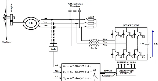
In this work, the topology using STATCOM have been chosen since it offers enhanced performance in terms of dynamic response and regulation compared with other available schemes specially when the produced voltage is low [5]. The fundamental principle of STATCOM is the generation of a controllable ac voltage source by a voltage source inverter (VSI) based on three phase sinusoidal pulse width modulation (SPWM) power converter technology such as IGBTs [6]. The ac side of the VSI is connected to the asynchronous wind turbine through a coupling reactance and its dc side to a capacitor. The active and reactive power transfer between the two systems is caused by the voltage difference across the reactance and can be controlled by the modulation index MI and the relative phase angle , Fig.1. Basically, there are two control objectives implemented in STATCOM. One is the PCC voltage regulation and the other is dc voltage regulation across its capacitor. In conventional scheme, a decoupled dq axis control approach based on four proportional integral (PI) type cascaded controllers is used [7]. Aside from experimental procedures, to the authors’ knowledge, there is no standard procedure for designing the ac voltage regulator that ensures the required stability and robustness to system variations. In general, the chosen set of PI gains remain fixed in daily operation of STATCOM. Since wind speed and load changes with time those parameters may not be suitable for all operating points [8]. Therefore, to reduce voltage fluctuation at all possible conditions we propose a new structure for ac voltage regulator based on Single-Input Fuzzy Logic Mamdani-type that depends only on the error between the reference value and the measured RMS value of the asynchronous wind turbine produced voltage.
The organization of this paper is as follows. It starts with the modeling of the studied asynchronous wind turbine and STATCOM, then focuses on the description of the conventional control scheme and the design of the proper current and voltage controllers, to finally discuss and analysis the simulated results.
2. POWER SYSTEM MODELING Asynchronous Wind Turbine Model
Several models of wind turbines have been developed and can be found throughout the bibliography [1]. Since the electrical behavior of the system is our main point of interest the following model is assumed:
Figure 2. Schematic diagram of the turbine model.
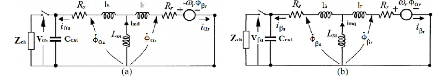
The induction generator model developed in this work is represented in reference frame, Fig.3. It should be noted that Lm is not a constant but a function of the magnetizing current im. This dependency have been experimentally
determined and incorporated into Matlab/Simulink environment.
Figure 3. Equivalent circuit of the SEIG in reference frame. The electromagnetic torque produced by the asynchronous generator is defined as:
𝐶𝑒𝑚= 𝑝. 𝐿𝑚
𝐿𝑟 (𝜑𝑟𝑑. 𝑖𝑠− 𝜑𝑟𝑞𝑖𝑠 ) (1)
Static Synchronous Compensator Model
The modeling of STATCOM is reviewed in the lines below and described in Park reference frame [8]. We define the reference frame coordinate where the d_axis is always coincident with the instantaneous system voltage vector and the q_axis is in quadrature with it. The equations describing the AC side of STATCOM are given by:
𝑑 𝑑𝑡[ 𝑖𝑜𝑡𝑑 𝑖𝑜𝑡𝑞] = [ −𝑅𝑐 𝐿𝑐 𝜔𝑠 −𝜔𝑠 − 𝑅𝑐 𝐿𝑐 ] . [𝑖𝑖𝑜𝑡𝑑 𝑜𝑡𝑞] + 1 𝐿𝑐[ 𝑉𝑑𝑠− 𝑉𝑜𝑡𝑑 𝑉𝑞𝑠− 𝑉𝑜𝑡𝑞] (2)
Where 𝜔𝑠 the pulsation of the generated voltage 𝑉𝑠 .
The voltage and current are related in the DC side of STATCOM by the following equation:
𝑑𝑉𝑑𝑐 𝑑𝑡 =
𝑖𝑑𝑐
𝐶𝑑𝑐 (3)
The switching function S of the VSI including the modulation index MI and the phase angle 𝛼 can be defined as:
𝑆 = [ 𝑆𝑢 𝑆𝑣 𝑆𝑤 ] = 𝑀𝐼. [ 𝑠𝑖𝑛 (𝑤𝑡 + 𝛼) 𝑠𝑖𝑛 (𝑤𝑡 −2𝜋 3 + 𝛼) 𝑠𝑖𝑛 (𝑤𝑡 +2𝜋 3 + 𝛼) ] (4)
The output voltages and currents of STATCOM are expressed as follows:
[𝑉𝑉𝑜𝑡𝑑 𝑜𝑡𝑞] = 𝑀𝐼. 𝑉𝑑𝑐. [ 𝑐𝑜𝑠 (𝛼) 𝑠𝑖𝑛 (𝛼)] (5) 𝑖𝑑𝑐= 𝑀𝐼. [𝑖𝑜𝑡𝑑 𝑖𝑜𝑡𝑞]. [𝑐𝑜𝑠 (𝛼) 𝑠𝑖𝑛 (𝛼)] (6)
THE 6TH EUROPEAN CONFERENCE ON RENEWABLE ENERGY SYSTEMS Istanbul/Turkey 25-27 June 2018
3. VOLTAGE CONTROL ARCHITECTURE Description
The main objective of the adopted command law is to regulate the AC voltage at PCC and the DC voltage of the VSI by performing a decoupled active and reactive power circulation between STATCOM and induction generator. This can be achieved by feeding or draining a sinusoidal current with a displacement of 90 degrees in relation to PCC voltage. STATCOM control parameters modulation index MI and phase angle 𝛼 are deduced from the inverter voltage references in Park reference frame. Thus, a PLL is used to synchronize the voltage output of STATCOM with the asynchronous generator voltage. The complete description of the control scheme is presented in Fig.4.
Figure 4. Control Scheme. Current Controller Tuning
The references of current loops 𝑖𝑜𝑡𝑑∗ and 𝑖𝑜𝑡𝑞∗are deduced from the active and reactive references of the converter 𝑄∗ and 𝑃𝑑𝑐∗ as shown in Fig.4. The current loop implemented uses a PI controller. Its frequency response is plotted in Fig.5. The phase margin of the system is about 90º and the setting time is 0.0109 seconds which allows a stable and fast response of the current controller as references change to meet the need for active and reactive power.
Figure 5. Current loops frequency response with controller parameters and performance. DC Voltage Regulator Tuning
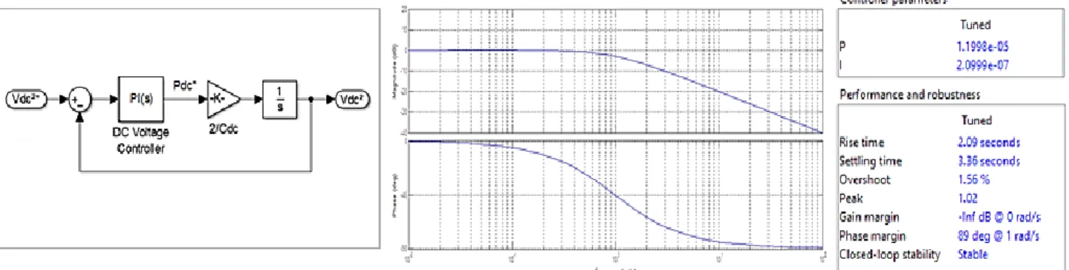
By sensing the voltage across the capacitor Cdc and comparing it to the reference value Vdc*, the DC voltage error can be eliminated using also a PI controller as shown in Fig.6. The inner d_axe current loop have a setting time faster than the DC voltage loop implemented.
AC Voltage Regulator Design
The Single-Input Fuzzy Logic Controller proposed in this work is constructed by choosing the error between the reference and the measured RMS value of the generated voltage as an input signal and dQ* as output signal, Fig.7. Hence, the reference reactive power to exchange with the IG is calculated using the following expression:
𝑄∗= ∑ 𝑑𝑄∗(𝑡) (7)
o If Vs_RMS is equal to the reference voltage value then error is equal to zero and dQ* must also be equal to zero to keep Q* at its previous value to avoid injection or absorption of any reactive power.
o If Vs_RMS is greater than the reference voltage value (inductive mode) the error will be negative and dQ* must be positive as well as Q* and its value should increase to absorb the excess of reactive power forcing then the generated voltage to drop to the rated value.
o If Vs_RMS is less than the reference voltage value (capacitive mode) the error will be positive and dQ* must be negative as well as Q* and its value should decrease to inject the needed reactive power forcing then the generated voltage to rise up to the rated value.
We define a simple structure for the fuzzy controller Mamdani-type with seven triangular rule-based-membership functions. The seven linguistic variables used are Negative Big (NB), Negative Medium (NM), Negative Small (NS), Zero (ZO), Positive Small (PS), Positive Medium (PM) and Positive Big (PB). The 7 rules have been built as represented in Fig.7.
Figure 7. Inputs and outputs membership functions of the SFLC (left) & Controller diagram (right) 4. SIMULATION RESULTS & DISCUSSION
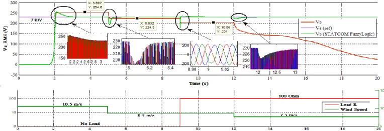
At no compensation mode (STATCOM disconnected), during the starting phase from the instant 0s to 2s, Fig.8, the SEIG is not yet excited so the voltage generated (phase to ground) is equal to 0V. After the second two, the output voltage grows exponentially until the steady-state RMS value of 254.6V. At the 5ths it drops to 224.5V when wind
speed changes from 10.5m/s to 8.5m/s at no load, and drops again at the 9ths to 204V when connected to a resistive
load of 100Ohm. Then, at the 12ths, the generated voltage starts collapsing when wind speed changes from 8.5m/s to
7.5m/s at full load. The observed change is caused by the reduction of the reactive power required by the asynchronous generator to keep the produced voltage at its rated value (Vs_ref).
THE 6TH EUROPEAN CONFERENCE ON RENEWABLE ENERGY SYSTEMS Istanbul/Turkey 25-27 June 2018
Once the STATCOM connected, Fig.8. The new simulation result shows that the desired steady state RMS value of the generated voltage is reached despite variation in wind speed or load. At t=2s the peak voltage reach 254.6V and decreases in 1.03 seconds creating so an overshoot of 10.7%. At t=5s Vs_RMS drops to 192.2V to create a deep of 16.52% which only lasts 0.3 seconds. At t=12s the PCC voltage drops again to 221.3V during 0.2s and rises up to stabilize at the reference value preventing the asynchronous wind turbine from collapsing. The SIFLC can so increases the performance of STATCOM to improve the asynchronous wind turbine voltage profile and stability when operating in both capacitive and inductive mode, Fig.9.
Figure 9. STATCOM reactive power variation as function of PCC voltage.
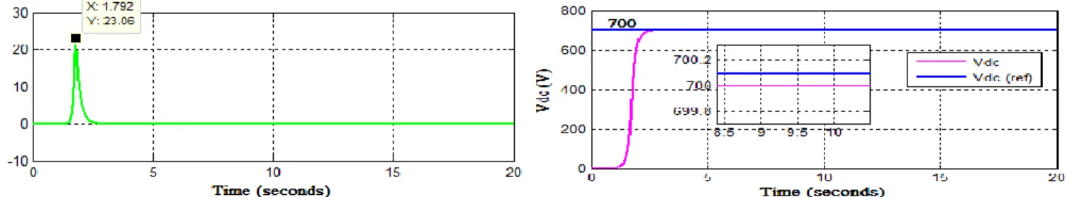
On the other hand, simulation results observed in Fig.10 shows that Vdc rises up at t=2s just after the excitation of the
SEIG and settles at the reference value proving so the efficiency of the designed DC voltage controller. The active power provided by the asynchronous wind turbine to STATCOM reach 23.06W to supply enough power to regulated Vdc then falls down to zero after 1.2 seconds since all losses are neglected.
Figure 10. STATCOM active power (left) & Vdc response (right). 5. CONCLUSION
In this paper, the model of an asynchronous wind turbine operating with STATCOM has been presented. The performance of the studied system under close loop condition at different wind speed and load circumstances using a SIFLC for PCC voltage regulation has been also investigated. Behavior analysis of the power system have shown the efficiency of the proposed command law which will be validated using real-time control board dspace 1104.
REFERENCES
[1] Elhafyani, M. L., Zouggar, S., Benkaddour, M., & Zidani, Y. (2006). Permanent and dynamic behaviours of self-excited induction generator in balanced mode. equilibrium, 1010, 3.
[2] Li, P., Adam, G. P., Holliday, D., & Williams, B. W. (2015, November). High power density STATCOM with extended reactive power control range. In Renewable Energy Research and Applications (ICRERA), 2015 International Conference on(pp. 710-715). IEEE.
[3] Anu, P., Divya, R., & Nair, M. G. (2015, June). STATCOM based controller for a three phase system feeding single phase loads. In Advancements in Power and Energy (TAP Energy), 2015 International Conference on (pp. 333-338). IEEE.
[4] Singh, B., Murthy, S. S., & Chilipi, R. S. R. (2014). STATCOM-based controller for a three-phase SEIG feeding single-phase loads. IEEE transactions on energy conversion, 29(2), 320-331.
[5] Sethy, S. K., & Moharana, J. K. (2012). Design, Analysis and Simulation of Linear Model of a STATCOM for Reactive Power Compensation with Variation of DC-link Voltage. International Journal of Engineering and Innovative Technology (IJEIT), 2(5).
[6] Jain, A., Joshi, K., Behal, A., & Mohan, N. (2006). Voltage regulation with STATCOMs: Modeling, control and results. IEEE Transactions on Power delivery, 21(2), 726-735.
[7] Baran, M. E., Teleke, S., Anderson, L., Huang, A., Bhattacharya, S., & Atcitty, S. (2008, July). STATCOM with energy storage for smoothing intermittent wind farm power. In Power and Energy Society General Meeting-Conversion and Delivery of Electrical Energy in the 21st Century, 2008 IEEE (pp. 1-6). IEEE.
[8] Perumal, B. V., & Chatterjee, J. K. (2006). Analysis of a self excited induction generator with STATCOM/battery energy storage system. In Power India Conference, 2006 IEEE (pp. 6-pp). IEEE.