Publisher’s version / Version de l'éditeur:
ASHRAE Transactions, 108, Pt. 1, pp. 712-723, 2002
READ THESE TERMS AND CONDITIONS CAREFULLY BEFORE USING THIS WEBSITE. https://nrc-publications.canada.ca/eng/copyright
Vous avez des questions? Nous pouvons vous aider. Pour communiquer directement avec un auteur, consultez la
première page de la revue dans laquelle son article a été publié afin de trouver ses coordonnées. Si vous n’arrivez pas à les repérer, communiquez avec nous à [email protected].
Questions? Contact the NRC Publications Archive team at
[email protected]. If you wish to email the authors directly, please see the first page of the publication for their contact information.
NRC Publications Archive
Archives des publications du CNRC
This publication could be one of several versions: author’s original, accepted manuscript or the publisher’s version. / La version de cette publication peut être l’une des suivantes : la version prépublication de l’auteur, la version acceptée du manuscrit ou la version de l’éditeur.
Access and use of this website and the material on it are subject to the Terms and Conditions set forth at
Initial investigations on plenum cable fires
Lougheed, G. D.; McCartney, C. J.; Kanabus-Kaminska, J. M.
https://publications-cnrc.canada.ca/fra/droits
L’accès à ce site Web et l’utilisation de son contenu sont assujettis aux conditions présentées dans le site LISEZ CES CONDITIONS ATTENTIVEMENT AVANT D’UTILISER CE SITE WEB.
NRC Publications Record / Notice d'Archives des publications de CNRC:
https://nrc-publications.canada.ca/eng/view/object/?id=856ad255-09ff-415d-86d8-53db5e4eed3e https://publications-cnrc.canada.ca/fra/voir/objet/?id=856ad255-09ff-415d-86d8-53db5e4eed3eInitial investigations on plenum cable fires
Lougheed, G.D.; McCartney, C.;
Kanabus-Kaminska, M.
A version of this document is published in / Une version de ce document se trouve dans : ASHRAE Transactions, v. 105, pt. 1, 1999, pp. 712-723
www.nrc.ca/irc/ircpubs
The following paper was published in ASHRAE Transactions, Vol.
105, Pt. 1.
1999
American Society of Heating, Refrigerating
and Air-Conditioning Engineers, Inc.
This posting is by permission of ASHRAE and is presented for
educational purposes only.
ASHRAE does not endorse or recommend commercial products or
services. This paper may not be copied and/or distributed
electronically or in paper form without permission of ASHRAE.
ABSTRACT
The potential increase in cable loads in building void spaces to support the increased use of computers and the re-cabling of local area networks (LANs) has raised concerns in the regulatory community regarding the potential impact on life safety. Specific concerns regarding exposed LAN cables installed in above-ceiling return air plenums resulted in ASHRAE initiating a research project with the National Research Council Canada to investigate the issue. The project on cable fires in plenums (RP-1108) includes surveys in North American buildings to determine the type and quantities of cable in return air plenums and fire scenarios that could poten-tially ignite the cables. It also includes fire tests performed at three scales: small, medium, and full. This paper provides preliminary results from the project including the building surveys. The results of bench and medium-scale tests are also discussed. The bench-scale tests, which were conducted using a cone calorimeter combined with FTIR gas analysis equip-ment to measure combustion by-products, are discussed. The medium-scale tests were conducted using a modified standard room fire test facility. These tests were used to investigate the effect of both thermal and flame exposure on communication cables.
INTRODUCTION
The use of ceiling voids for nonducted return ventilation air is an increasingly common practice in modern commercial buildings (Clarke et al. 1993). It is also common practice to route communication cables through hidden voids in build-ings: underfloor spaces, vertical riser spaces, and ceiling plenum spaces. In those cases in which the void space is also used as part of the normal HVAC system, there is the potential,
in the case of a cable fire, to spread heat and smoke to all inhab-ited parts of the building.
With the rapid increase in computer-based information technology, there is a corresponding rise in the demand for cabling to support it. It is estimated that computer usage is increasing at a rate of 20% per year and local area networks (LANs) are re-cabled approximately every three years (Fardell 1998). This new cabling may be installed over multi-ple layers of older cables, potentially resulting in a high fuel load in concealed spaces.
The potential increase in cable loads in plenums resulting from the increased use of computers and re-cabling of LAN systems has raised concerns in the regulatory community (Clarke and Gewain 2000). Specific concerns regarding the potential impact on life safety of exposed LAN cables installed in above-ceiling return air plenums resulted in ASHRAE initiating a research project with the National Research Council Canada.
The project on cable fires in plenums (RP-1108) includes surveys in North American office buildings to determine the type and quantities of cable in return air plenums and fire scenarios that could potentially ignite the cables. It also includes fire tests performed at three scales: small, medium, and full. The bench-scale tests discussed in this paper were conducted using a cone calorimeter. Medium-scale tests conducted using a modified standard room fire test facility are also discussed. Tests conducted in this facility were used to investigate the behavior of communications cable under a range of simulated fire conditions that could occur in nonducted air-handling ceiling plenums. Fourier transform infrared (FTIR) spectrometers were used with both the bench-and medium-scale tests to measure selected combustion
by-Initial Investigations on Plenum Cable Fires
Gary D. Lougheed, Ph.D.
Cameron McCartney
Malgosia Kanabus-Kaminska, Ph.D.
Member ASHRAE
Gary D. Lougheed is a senior research officer and Cameron McCartney and Malgosia Kanabus-Kaminska are senior technical officers in the Fire Risk Management Program, Institute for Research in Construction, National Research Council Canada, Ottawa, Ontario.
ASHRAE Transactions: Symposia 713 products in addition to the standard gases (CO, CO2, and O2)
typically measured in fire tests. The results of the bench- and medium-scale tests, along with the building surveys, were used as input for the development of a full-scale fire test program. This paper provides preliminary results for the project.
BUILDING CODE REQUIREMENTS
One approach used in building codes to limit the impact of a fire is by placing limits on the materials used for building construction. The principal control on accepting combustible materials starts with the type of construction: combustible or noncombustible. The type of construction required is depen-dent on factors such as building height, building area, and occupancy classification.
Most materials in combustible construction are not specifically regulated apart from flame-spread rating for surfaces. For noncombustible construction, the assumption is that all construction materials are noncombustible unless specifically permitted. The permission is prescriptive in nature, provided by listing the specific materials and the attributes the materials must satisfy including flame spread rating and smoke development.
By specifying the use of noncombustible materials for building construction, the fuel load in a building is decreased relative to combustible construction. As a consequence, the hazard of fire for occupants is reduced.
The classification of a material as noncombustible is determined using a small-scale furnace operating at 750°C (ASTM 1998; ULC 1980). This is a severe pass/fail test. Typi-cal materials that are classified as noncombustible include brick, concrete, plaster, metals, glass, and rock.
Fires in concealed spaces are of particular concern because of the potential for the undetected spread of fire and smoke throughout a building. As shown by the fire at the Dusseldorf Airport (Comeau 1996), it is very difficult for the fire services to attack such fires. Also, fires can readily spread in concealed spaces causing considerable damage even if the building is protected with a sprinkler system (Comeau and Duval 1997).
Although detectors may be installed in concealed spaces, the practice is not universal. Also, under certain conditions, NFPA 13 (NFPA 1999a) does not require the installation of sprinklers in noncombustible concealed spaces. For example, based on Section 4-13.1.1, Exception 10, sprinklers are not required in noncombustible concealed spaces containing insu-lation where the heat content of the insuinsu-lation installed in the space does not exceed 11 356 kJ/m2.
For buildings required to be of noncombustible construc-tion, current installation standards and codes such as NFPA 90A (NFPA 1999c) require materials in air-handling plenums to be noncombustible or limited combustible. The standards permit exceptions to this requirement if the materials are tested in accordance with specific fire test standards. The fire
test standards used for wire and cables are discussed in the following section.
STANDARD FIRE TESTS FOR WIRE AND CABLES
Since the 1950s, a wide range of standard fire tests has been developed for wire and cables. Many of these tests are used for regulatory purposes to subdivide cables into catego-ries depending on the required fire performance based on fire propagation characteristics. For communication cables, there is a formal hierarchy of fire tests covering a wide range of severity depending on cable usage (Hirschler 1997).
In North America, the toughest fire propagation require-ments, as well as low-smoke requirerequire-ments, are for communi-cation cables used outside of metallic conduit in air-handling plenums. NFPA 90A (NFPA 1999c) requires that all materials exposed to the airflow be noncombustible or limited combus-tible and have a maximum smoke developed index of 50. A limited combustible building construction material is defined as a material that does not pass the noncombustibility test and that, in the form in which it is used, has a potential heat value not exceeding 8 141 kJ/kg. The potential heat is determined using a bomb calorimeter in accordance with NFPA 259 (NFPA 1998).
For electrical wires and cables and optical fiber cables, NFPA 90A provides an exception to the noncombustibility/ limited combustibility requirement. To meet the require-ments in the exception, the wire and cables are tested in accordance with the UL 910 test (UL 1998) or the equiva-lent NFPA 262 (NFPA 1999b) using the 7.6 m Steiner tunnel, which is used to determine flame spread ratings for construction materials (ASTM 1999). For the tunnel test, a 0.3 m wide and 7.6 m long array of cables are placed on a ladder and exposed to a gas burner flame with a nominal heat output of 90 kW for 20 minutes. Ventilation air is supplied from the burner end with an airflow velocity of 1.2 m/s. The pass/fail criteria for plenum cable were initially developed by comparing the performance of conventional cable in metal conduit to the performance of a cable proposed for listing as a plenum cable (Przybyla et al. 1981). In order to pass the UL 910/NFPA 262 test, the extent of flame spread beyond the gas flame must be no more than 1.5 m (NFPA 1999c). In addition, the peak and average smoke optical density must not exceed 0.5 and 0.15, respectively. Cables that pass the tunnel test are desig-nated as communication plenum (CMP) cable.
At present, NFPA 90A (NFPA 1999c) allows unlimited quantities of CMP rated cable in air-handling plenums. Because of concerns regarding the accumulation of cables in plenums, there have been recent efforts in the U.S. to restrict the fire performance for such cables to limited combustible and a maximum smoke developed index of 50 (Clarke and Gewain 2000).
In terms of fire propagation performance requirements, riser cables must meet the next most severe requirement by passing the UL 1666 (UL 2000). This test procedure is used for
communication cables when the cable is to be installed outside of metallic conduit in building riser shafts. This is a vertical cable test where the cables are mounted in a 5.8 m high concrete shaft that is divided into two compartments at the 3.7 m height. There is a 0.3 m by 0.6 m opening between the two compartments. The ignition source is a gas flame with a heat output of 145 kW for 30 minutes. The cables pass the test if there is no flame at the top of the lower compartment during the test. The cables that pass this test are designated as commu-nication riser (CMR) cable.
The next category of cables are those that pass vertical tray fire tests including UL 1581-1160 (UL 1997a), CSA FT4 (CSA 1996), and IEC 60332-3 (IEC 2000a). In the U.S., cables that pass the vertical tray test are designated as CM and are allowed for general use. In some jurisdictions in Canada, cables that pass the vertical tray test and are designated as FT4 can be used in noncombustible construction including air-handling plenums (NRC 1995). The basis for using the FT 4 rating is discussed in a paper by Mehaffey and Richardson (1985). Other Canadian jurisdictions require the use of FT6 rated cables in noncombustible construction determined using a tunnel test (ULC 1987).
For the UL 1581-1160 test (UL 1997a), a 2.4 m high and 300 mm wide vertical cable tray is loaded with cables and exposed to a 20.3 kW gas flame for 20 minutes. The gas burner is mounted horizontally at a height of 0.46 m above the bottom of the tray. The cables pass the test if the length of the char does not reach the top of the tray.
The CSA-FT4 test (CSA 1996) uses a 3.6 m high tray. The burner is mounted at a 20° angle and is located 0.3 m above the base of the cable tray. The cables pass the test if the char length does not exceed 1.5 m.
The final category of cables are those that pass UL 1581 VW1 (UL 1997b) or IEC 60332-1 (IEC 2000b). These test procedures are used for those cables that are listed as flame retardant. The UL 1581 test uses a small burner inside a metal enclosure on a 450 mm length of cable. The cable passes if, after five 15-second exposures to the flame, it does not burn more than 0.25 m, does not drip enough to ignite a cotton swab placed on the floor, and does not continue to burn for more than 1 minute in the absence of the ignition source. Cables that pass this test are designated as CMX.
RECENT RESEARCH ON WIRE AND CABLES
In recent years, three major research programs have been conducted to address issues related to the fire performance of electrical wire and cables including those used for high-density communication installations. These projects are summarized in this section.
The National Fire Protection Research Foundation (NFPRF) has undertaken a study entitled International Limited Combustible Plenum Cable Test Project. Preliminary results of this project are available (Clarke and Gewain 2000). The goal of the project is to determine how to use NFPA 255
(NFPA 1996) and NFPA 259 (NFPA 1998) to test and evaluate wire and cable. Specific objectives include, among others: • Develop harmonized Steiner tunnel listing protocols for
limited combustible plenum cables related to NFPA 262/UL 910 and NFPA 255 (NFPA 1996).
• Document calorimeter design and test criteria based on NFPA 259 (NFPA 1998) to accommodate samples. • Conduct literature search and full-scale plenum
refer-ence tests for limited combustible plenum cable. Over the past decade or more, there has been extensive research at the Building Research Establishment (BRE) in the U.K. on wire and cable fires in concealed spaces (Fardell 1998). Much of this work was focused around a large-scale cable test rig consisting of a fire-hardened test compartment. A suspended ceiling was used to form the plenum space. Addi-tional details regarding the test facility are provided by Fardell et al (1996).
Wood crib fires and propane burner fires with a nominal output of 1 MW for 30 minutes were located in the lower portion of the test compartment. These test fires were used to ignite cable samples located in the plenum space through an opening in the ceiling. The research with this facility was primarily directed at investigating the impact of wire and cable materials on fire performance. It has also been used to verify standard test methods based on the Steiner tunnel as well as other test methods used to evaluate the fire performance of wire and cable in terms of their flammability and their poten-tial to produce smoke and toxic combustion products. Fardell (2000) provides an overview of the recent research efforts.
The third major project was entitled Fire Performance of Electric Cables (FIPEC). This project was funded by DG XII of the European Commission as well as European cable manu-facturers, compounders, cable users, and government research bodies. The objectives of this project were as follows (Gray-son et al. 2001):
• To develop or modify fire test methods for electrical cables offering improvements on existing IEC test meth-ods.
• To develop or adapt the cone calorimeter test method in order to be able to use it for small-scale testing of elec-trical cables.
• To develop a correlation model for the prediction of the fire performance of electrical cables based on results of small-scale tests.
• To develop bases for a calculation model for the predic-tion of realistic fire performance of electrical cables in some key constructions based on the results of small-scale tests on materials.
• To investigate the validity of models comparing the out-put from the models with realistic design fire test data. The FIPEC project had a much broader scope than the NFPRF and BRE programs that were focused primarily on
ASHRAE Transactions: Symposia 715 LAN installations. In particular, the FIPEC project
encom-passed general fire testing for electric cable covering major installation scenarios, including power plants, vehicles, tunnels, and occupancies, with the latter group covering cable installations in riser shafts and ceiling and underfloor voids. A detailed report for the project is available (Grayson et al 2000).
BUILDING SURVEYS
As discussed previously, there are suggestions that the quantity of exposed cable in plenums is increasing dramati-cally due to the rapid growth of LAN systems and frequent re-cabling of office spaces to satisfy the demand for personal computers and other electrical and electronic devices. The growth of the Internet has significantly increased communi-cations over LANs. For example, from 1991 to 1997 plenum cable has grown by 46%, and from 1997 to 2000 it was expected to grow another 20% annually (Clarke et al 1993; Hoover et al 1997).
At present, there are no limits in codes and standards as to the quantity of exposed cable that is allowed in plenums. One objective of this project was to conduct building surveys in North American office buildings to determine the location and the amount of cable in plenum spaces in office buildings. These surveys were also used as the basis for determining fire scenarios for use in full-scale fire tests with communication cables. Surveys were conducted in office buildings in both the U.S. (Baltimore/Washington and Chicago areas) and Canada (Montreal, Ottawa, and Toronto). The full results of the surveys will be provided in the final report for the project. In this paper, a brief summary of some of the findings used in developing the fire test program is provided.
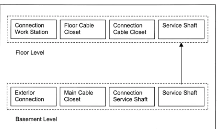
Figure 1 shows schematically a communication cable installation in a typical high-rise office building starting with the exterior building connection. The complete cable installa-tion, including both basement and occupied floor areas, is shown for completeness. However, for this project, the primary focus was on the cable installation in the occupied areas of an office building.
The possible locations for cables in a typical office build-ing and the related fire exposures are as follows:
• Exterior building connection. Main trunk cables are used to connect from the exterior services to the main cable closet typically located in a basement level. These cables can run directly into the main cable closet through the exterior wall. In other cases, the trunk cables may run through various spaces in the basement level including storage and service areas. In the latter case, the cables could potentially be exposed to a fire in the building space.
• Main cable closet. In the main cable closet, the interior building communication system is connected to the exterior trunk cables using patch cable systems. The cable load in the cable closet depends on the occupant loading for the building. For a high-rise office building, there can be significant amount of cable in these spaces. Typically, these rooms have limited access and are iso-lated from adjacent spaces by fire separations. However, in the building surveys, it was noted that in some cases the penetrations through the wall and floor assemblies were not fire stopped or improperly fire stopped. Igni-tion sources were limited in these spaces. The primary fire scenario would be the ignition of stored or miscella-neous materials that were observed in some buildings. • Service shaft connection. Depending on the building
layout, the interior cable system can connect directly into service shafts for distribution to the upper floor lev-els. However, in many cases, as with the trunk cables, the cables can run through various spaces in the base-ment including storage and service area to reach the ser-vice shaft and could potentially be exposed to a fire in these areas.
• Service shaft. The communication cable system is typi-cally distributed to the upper building floors through service shafts. The penetrations through the floors are fire stopped. Cables installed in both dedicated and multi-purpose shafts were observed. Other services installed in multi-purpose shafts included power cables and plumbing systems. Typically, the service shafts have limited access and are isolated from adjacent spaces by fire separations. The primary fire scenario would be the ignition of stored or miscellaneous materials that were observed in some buildings.
• Cable closet connection. For communication cables installed in dedicated shafts, the cable closet on the indi-vidual floor levels was either in or adjacent to the ser-vice shaft. However, in some cases, the cable closet was in another area of the building requiring cable runs through the building area. This included cable installa-tions in the air-handling plenum above various spaces in the floor area, including both office areas and storage areas. These cable runs could potentially be exposed to a fire in these areas.
• Floor cable closets. In the floor cable closets, the cables that run through the service shafts are connected to the cables for the individual workstations using patch cable systems. Different cable closet setups were observed
during the building surveys. In many cases, dedicated areas in or adjacent to the service shaft were used. Typi-cally, these areas have limited access and are isolated from adjacent spaces using fire rated separations. Dur-ing the buildDur-ing surveys, it was noted that in some cases the penetrations through barriers were not fire stopped or improperly fire stopped. Ignition sources were lim-ited in these areas. The primary fire scenario would be the ignition of stored or miscellaneous materials that were observed in some buildings.
In other cases, the cable closet was combined with a computer room that provided both internal and external network services. For larger computer rooms, a separate HVAC system was typically used to meet the high cooling demands typical of such facilities. However, smaller ad hoc installations were also noted, with the building HVAC system used for the room area. Access to the computer rooms is usually limited. However, there is more day-to-day usage then in a dedicated cable closet. Also, more furnishings, including workstations, were observed in these spaces, increasing the fuel load.
The cables exiting the cable closets and computer rooms were rated for plenum applications. However, within the computer room, general usage cables were used as patch cables to make the connection between the cables used in the service shafts and the cable runs to the floor area. As a result, cables with a wide range of ratings are present in these spaces. In the case of small ad hoc computer rooms, cases were noted in which the patch cable connections were made through the ceiling void space. If the cable closet or computer rooms are not isolated from the adjacent floor areas, including the plenums used for air handling, there can potentially be considerable amounts of nonplenum rated cable both inside the room and in the ceiling void. The use of nonple-num rated cable in the ceiling void space is non-code-conforming and will not be investigated as part of this project.
• Workstation connections. The final link in the cable installation is the connection from the cable closet to the individual workstations. A single length of plenum rated cable is typically used for this connection. In recent con-struction, cable channels are sometimes located in the building floor for distributing the cables to the worksta-tions. In other cases, the cables are distributed through the ceiling voids. The latter is the scenario being investi-gated in this project. Of particular interest is the case in which the ceiling void is also used for air handling pur-poses.
The primary ignition source located in the ceiling void space is the electrical installations for lights and other services. However, in most high-density communication cable installations, the communication cables were run using dedi-cated systems. For example, hanger systems were mounted in
the ceiling/floor slab. In these cases, the communication cables were isolated from the electrical systems. Also, the fire performance for communication cable used in plenums is assessed using ignition sources with high heat output. The more likely fire scenario that could impact on communication cables in a plenum space is a fire in the occupied space. This is consistent with the fire scenarios used in the BRE full-scale fire test program (Fardell et al 1996; Fardell 1998, 2000). This scenario will be the focus of this project.
There are a number of fire scenarios that could involve cable installations in the basement level. However, most of these scenarios do not involve the ceiling void spaces that are the subject of this study. There are exceptions where the lowest building level is also occupied. In this case, the fire scenarios are similar to those on the upper floor levels. As such, the fire scenarios developed for this project were based on the situa-tions found in the upper floor levels.
For occupied floor levels, two primary fire scenarios were observed. The scenario of particular interest was for plenum rated cables located in a plenum space with ignition from a fire located in the space below. The second scenario was for cables located in a cable closet or computer room with a fire involv-ing furnishinvolv-ings and stored/miscellaneous items as the ignition source. Both of these situations will be investigated in the full-scale tests conducted for this project.
One of the main issues to be addressed with the building surveys was the cable fire load in the ceiling void. A number of previous studies have noted the potential for the buildup of cables with the installation of new generation cables (Clarke et al 1993; Hoover et al. 1997). However, it was determined in this study that many building owners are having older gener-ations of cable removed, especially if major renovgener-ations of the floor space are undertaken. An estimate of the incremental fire load for cable installations is provided in a subsequent section.
SMOKE GAS ANALYSIS
For cable fires, a measurement of the production rate of acid gases and other smoke components is of particular inter-est. As such, FTIR spectrometers were used in conjunction with the tests conducted for this project.
Recently, FTIR (Fourier transform infrared) spectrome-ters are being used for smoke gas analysis (Su et al. 1998; Hakkarainen et al. 2000; Kanabus-Kaminska et al. 2001). The FTIR spectrometric technique allows simultaneous observa-tion in real time and quantificaobserva-tion of many volatile compounds that have characteristic absorption bands in the infrared region of the spectrum. This includes the major combustion products (CO and CO2) traditionally measured by specialized infrared analyzers, as well as minor smoke compo-nents: hydrogen cyanide and other nitriles, acid gases and precursors (HF, HCl, HBr, carbonyl halides, SO2, NOx), irri-tants (acrolein, formaldehyde), and hydrocarbons (methane, ethylene, acetylene).
CONE CALORIMETER TESTS
A broad range of data communication cables is available in the North American market. Bench-scale tests were conducted using a cone calorimeter to provide an initial eval-uation of the fire performance of representative data commu
-ASHRAE Transactions: Symposia 717 nication cables. For these tests, ten cables were purchased on
the open market. The signal transmission performance of the cables was Category 3 and Category 5. These categories of cable have been used extensively for data communication purposes over the past decade or more. All the cables were unshielded twisted pair (UTP) with four pairs of wires. The cables were selected from the major North American manu-facturers to represent a cross section of cable types and ratings presently used in office buildings. The cables tested included eight that were labeled as CMP, thus meeting the requirements for use in air-handling plenums in the U.S. In addition, two cables were labeled as FT4, meeting the requirements for some jurisdictions in Canada.
The bench-scale tests were conducted using the ASTM E 1354 cone calorimeter (ASTM 1997) with a heat flux of 50 kW/m2. Specimen mass loss and smoke production were recorded. Any gases produced were sampled and analyzed using standard gas analyzers for O2, CO, and CO2 to deter-mine the heat release rate. In addition, the combustion gases were analyzed for all ten samples using an FTIR spectrome-ter to measure other combustion by-products including HF and HCl.
For the cone tests, the cable was cut into 100 mm lengths. These cable lengths were placed side by side on a metal wire mesh in the cone calorimeter holder. An air gap was main-tained between the supporting mesh and a thermal liner on the bottom of the holder. The ends of the cables were unsealed.
A summary of the cone calorimeter results for each cable is provided in Table 1. Each cable is referenced by a letter designation. The results provided in the table are the average of three tests.
Based on an overall analysis of the cone calorimeter and FTIR results, the ten cables were grouped as three general types. The jacket material for all the cables was PVC based. The insulator materials were polyolefin (Type 1—Cables B, G, H, and J), flouropolymer (Type 2—Cable C), and perfluo-ropolymer (Type 3—Cables A, D, E, F and I). There were two
Type 1cables with a CMP rating (Cables G and H) and two with an FT4 rating (Cables B and J). There were other fillers and additives in the cable jacket and insulators that were not specifically identified. Further results for three cables (Cables B, C, and D) that are representative of the three groups are discussed below.
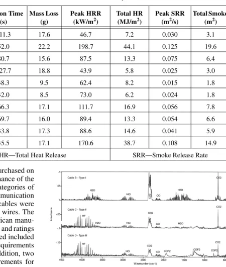
FTIR spectra averaged over the 30- to 410-second time period are shown in Figure 2 for Cables B, C, and D. The vari-ous gas species produced during the test are indicated. For the Type 1 cables (Cable B), the main secondary combustion by-product was the acid gas HCl.
The spectra for Cables C and D were typical of those measured for the two other groups of cables. In both cases, HCl and HF acid gases were produced. Additional peaks in the spectra indicated that a number of other compounds were produced. The primary difference between the two types of cables was the presence of COF2 that was produced from the perfluoropolymer used as the insulator material in the Type 3 cables.
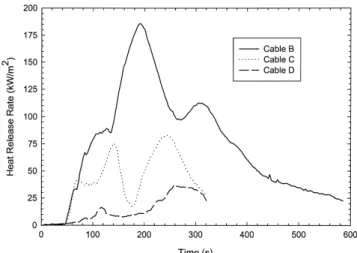
The heat release rates for Cables B, C, and D are shown in Figure 3. The cables can be ranked in terms of heat release
TABLE 1
Summary of Cone Calorimeter Results at 50 kW/m2 Exposure
Cable Rating Type
Initial Mass (g) Ignition Time (s) Mass Loss (g) Peak HRR (kW/m2) Total HR (MJ/m2) Peak SRR (m2/s) Total Smoke (m2) A CMP 3 63.9 111.3 17.6 46.7 7.2 0.030 3.1 B FT4 1 60.0 52.0 22.2 198.7 44.1 0.125 19.6 C CMP 2 62.7 80.7 15.6 87.5 13.3 0.075 6.4 D CMP 3 68.6 227.7 18.8 43.9 5.8 0.025 3.0 E CMP 3 64.7 48.3 9.5 62.4 8.2 0.015 1.8 F CMP 3 68.8 42.0 8.5 73.0 6.2 0.024 1.8 G CMP 1 60.5 66.3 17.1 111.7 16.9 0.056 7.8 H CMP 1 60.4 69.7 16.0 89.4 13.3 0.054 6.6 I CMP 3 64.7 33.8 17.3 88.6 14.6 0.041 5.9 J FT4 1 55.8 45.5 17.1 170.6 38.7 0.108 14.9
HRR—Heat Release Rate Total HR—Total Heat Release SRR—Smoke Release Rate
Figure 2 Time averaged FTIR spectra for Cables B, C, and D measured using cone calorimeter and FTIR.
rate parameters with the highest heat output for the Type 1 cables with an FT4 rating and the lowest output for the Type 3 cables. The one outrider in the Type 3 group was Cable I (Table 1). This cable had comparable total heat release rate as the Type 2 cable and the Type 1 cables with a CMP rating. The heat release rate results for Cable I indicated higher heat output during the initial stages of the test then other cables in this group, indicating a difference in the jacket material.
Cone calorimeter tests for CMP rated cables were also conducted as part of the NFPRF project with 35, 50, and 75 kW/m2 exposures (Clarke and Gewain 2000). Overall the range of results for the CMP cables (mass loss, peak heat release rate, total heat release rate, smoke release rate, and total smoke production) tested in this project overlap with those measured in the NFPRF project. For example, the peak heat release rates for the CMP cables used in this project were 40-110 kWm2 compared with 20 kW/m2 to 80 kW/m2 in the NFPRF study. This overlap would be expected in that the Type 3 cables used in this project should have heat outputs comparable to the cables used in the NFPRF project.
The HCl concentrations measured for Cables B, C, and D are shown in Figure 4. In all cases, the HCl production started at approximately the same time with the initial emissions prior to ignition. The HCl was produced from the PVC materials in the cable jackets. Peak HCl concentrations of 500-1000 ppm were measured between 150 and 200 seconds. For Cable C, the highest production of HCl occurred just prior to the rapid decrease in heat release rate that followed the initial peak heat output.
The HF concentrations measured for the same three cables are shown in Figure 5. For the Type 1 cables, no HF was produced. For the Type 2 and 3 cables (Cables C and D), peak HF concentrations between 1000 and 1400 ppm were measured between 250 and 300 seconds. These times corre-sponded approximately to the second peak in the heat release resulting from the destruction of the insulator materials.
Overall, the results shown in Figures 3-5 are indicative of the general trend in the cone calorimeter results for the three types of cables. In the initial phase, the primary material involved in the combustion process was the cable jacket, resulting in the initial heat release rate and the production of HCl. At a later stage, the insulator became involved, resulting in further heat output and the production of HF from those cables with fluoropolymer insulators.
CABLE FIRE LOAD
In the following, the survey for a building in Montreal is used to provide an indication of cable quantities in a ceiling void used as an air-handling system. The reasons for using this building for this analysis are as follows:
• It is a typical high rise (>20 storeys) office building that, in the upper floor levels, has a simple square floor plan (approximately 900 m2) with the center core used for services.
• Several floor levels for one of the building occupants were in the process of being converted from a standard
Figure 3 Heat release rates for Cables B, C, and D using cone calorimeter.
Figure 4 HCI concentrations for Cables B, C, and D.
ASHRAE Transactions: Symposia 719 open plan office system to one using a high-density pod
system to increase the number of workstations on each floor to 100-120. This results in an increased number of communication cables required on each floor level. • These renovated floor levels were being used to house a
call-in center for a major utility. Three communications cables (one voice and two data links) were being installed at each workstation. The cable length used for each drop was typically a maximum of 95 m.
With the links to the workstations as well as other links in the center core, approximately 400 cable drops were being installed on each floor. Each cable drop was approximately 45 m long, giving an estimated total cable length of 18 000 m. Assuming a typical Category 5 communication cable with 30 g/m, the total cable load is approximately 340 kg, giving a cable loading on the floor of 0.4 kg/m2. Based on the cone calorimeter results, the total heat output for CMP rated cable is between 1.5 and 3 MJ/kg compared with 9-10 MJ/kg for FT4 rated cable based on the total weight of the sample. Using these data, the specific fire load (heat content of combustibles/unit floor area) in the building, assuming CMP cable, is 1.2 MJ/m2 and 4.2 MJ/m2 for the FT4 cable.
The cone calorimeter results are representative of results for a given fire exposure test. It does not necessarily measure the total potential heat output for a sample. In the NFPRF study, the potential heat measured using a bomb calorimeter (NFPA 259) was reported for CMP rated cables (Clarke and Gewain 2000). The total heat output ranged from approxi-mately 3 to 7 MJ/kg. Using these data, the contribution of the cables to the specific fire load (heat content of combustibles/ unit floor area) in the building was 1.8-4.2 MJ/m2. For comparison, the specific fire load for the inhabited spaces in
an office building is 467 MJ/m2 (Mehaffey and Richardson 1985).
The difference in heat output using NFPA 259 and the cone calorimeter is approximately a factor of 3. Using this factor, the estimated specific fire load for FT4 cable is approximately 12.6 MJ/m2. For comparison, if the cables are assumed to be approximately 50% copper wire and using the heat of combustion for polyethylene (46.6 MJ/kg), the esti-mated specific fire load for FT4 cable would be approxi-mately 17.3 MJ/m2. This would suggest 12.6 MJ/m2 is a realistic estimate for the specific fire load with FT4 cable.
The specific fire load estimates provided in this section are based on the single generation of cables observed in the building. The estimates can be extrapolated to include multi-ple generations by assuming an additional 4500 m of installed cable for each additional set of cables required for 100 drops.
MEDIUM-SCALE TESTS
Medium-scale tests were conducted using a modified standard ISO 9705 room fire test facility (ISO 1989). This facility consists of a small noncombustible room with a single doorway and a high-capacity hood and duct system to collect the combustion gases (Figure 6). For the cable tests, propane burners were used to produce repeatable fires, which gener-ated a specified temperature at the specimen location in cali-bration tests without cables. Cable specimens were installed in realistic configurations just below the ceiling of the test facil-ity. They were tested over a range of temperature conditions (200°C, 350°C, and 450°C) as well as with direct fire expo-sure. For the three temperature exposures, the propane burners were located at floor level. A heat release rate in the range of 200-350 kW was required for the three temperature exposures. For the direct flame exposure, the propane burner was raised
such that the flame produced at a heat release rate of approx-imately 300 kW engulfed the cable. The test duration was between 15 and 30 minutes with the longer exposures typi-cally used for the tests at lower temperatures.
Measurements included mass loss rate, smoke produc-tion, and heat release rates. In addiproduc-tion, gas samples were taken from the room exhaust duct and analyzed using both standard gas analyzers and the FTIR.
One objective of these tests was to determine the behavior of the communication cables under a range of simulated fire conditions. In particular, the tests were designed to investigate the thermal degradation of the cables under a range of thermal conditions that could occur for fires in the occupied area of an office building. In this case, the hot gases would enter the ceil-ing void space exposceil-ing the communication cable to elevated temperatures. The exposure temperatures will depend on whether the occupied area is sprinklered.
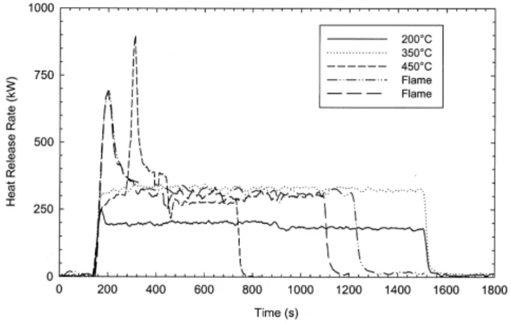
The medium-scale tests were conducted with the three cables selected as being representative of the cables tested using the cone calorimeter. The cables used were Cable B (Type 1 with an FT4 rating), Cable C (Type 2), and Cable D (Type 3). The heat release rates produced under the four expo-sures for the cables are shown in Figures 7-9. The HCl and HF concentrations measured in the exhaust duct for tests with Cable C are shown in Figure 10.
For the tests at an exposure of 200ºC, there was no measurable heat release rate for the three cables (Figures 7-9). Also, no secondary combustion by-products were measured including HCl (Figure 10). This is to be expected since PVC-based materials such as those in the cable jackets require temperatures >225-250ºC for initial thermal decomposition of the polymer. These tests were conducted as null or baseline tests.
Based on physio-thermal and chemical properties for halogen-based polymers, noticeable degradation/decomposi-tion of PVC-based materials will occur when exposed to temperatures of 350ºC. This was generally confirmed with the room tests. For example, the results for tests with Cable C are shown in Figure 10. Limited amounts of HCl were produced, indicating a limited thermal breakdown of the PVC jacket.
Figure 7 Heat release rates for medium-scale tests with Cable B.
Figure 8 Heat release rates for medium-scale tests with Cable C.
Figure 9 Heat release rates for medium-scale tests with Cable D.
ASHRAE Transactions: Symposia 721 However, there was no HF production to indicate a breakdown
of the fluoropolymer insulator. Also, for all cables, there was no measurable heat release rate (Figures 7-9).
Again, based on physio-thermal and chemical properties, a thermal exposure of 450ºC was expected to have a major impact on the PVC-based jacketing material used for the cables as well as the flouropolymers used as insulation mate-rial. This is generally confirmed by the FTIR measurements shown in Figures 11 and 12for the three cables tested. HCl production started at the same time for all three cables and was dominant during the initial stages of the test. For the two CMP rated cables (Cable C and D), HF was produced in the later stages of the test.
The performance of the FT4 cable (Cable B) was different from the two CMP cables at the 450ºC exposure. Figure 11 indicates there was an initial breakdown of the PVC jacketing material as evidenced by the HCl production (Figure 11). Subsequently, there was a rapid increase in heat release rate with a peak output of approximately 1000 kW (Figure 7).
For this test, there was no ignition source at the cable height. The rapid fire development was most likely a result of the oligomeric vapor cloud produced by the decomposition of the polyolefin insulator expanding in the room and eventually being ignited by the propane burner. Further tests with a local ignition source are planned at 350°C and 450ºC to investigate the impact of piloted ignition on the fire scenario.
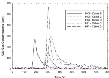
Tests were also conducted with the cables immersed in the propane burner flame. The HCl and HF concentrations measured in these tests are shown in Figure 12. For all the cables, HCl was produced in the initial 150-300 seconds. For the CMP cables, the HCl was followed by the production of HF.
When immersed in the propane burner flames, all three cables ignited. The heat release rate results shown in Figures 7 for Cables B and C indicate the peak heat release rates were comparable (700 kW). Lower heat release rates were measured for Cable D.
SUMMARY
This paper provides preliminary results for the joint ASHRAE and NRC project to investigate fires involving communication cables installed in air-handling plenums. As part of this project, building surveys were conducted in North American office buildings. Based on these surveys, a general discussion of LAN installations and potential fire situations are provided.
For occupied floor levels, two primary fire scenarios were observed. The scenario of particular concern was for cables located in a plenum space with ignition from a fire located in the space below. The second scenario was for cables located in a cable closet or computer room with a fire involving furnishings and stored or miscellaneous items as the ignition source.
One of the main issues to be addressed with the building surveys was the cable fire load in the ceiling void. A number of previous studies have noted the potential for the buildup of cables with the installation of new generation cables (Clarke et al 1993; Hoover et al. 1997). However, indications in this study are that many building owners are having older gener-ations of cable. Also, based on the building surveys, an esti-mate of the cable loading in the plenum space using a high-rise office building case is provided.
There is a broad range of data communication cables available on the North American market. Bench-scale tests were conducted using a cone calorimeter combined with FTIR gas analysis to provide an initial evaluation of the fire perfor-mance of representative data communication cables. For these tests, ten cables were purchased on the open market. Based on an overall analysis of the cone calorimeter and FTIR results, three representative cables were chosen for use in medium-and full-scale fire tests. These were the cables designated as Cables B, C, and D in Table 1.
Medium-scale tests were conducted using a modified standard ISO 9705 room fire test facility (ISO 1989). This test
Figure 11 Acid gas concentrations for Cables B, C, and D with 450ºC exposure.
Figure 12 Acid gas concentrations for Cables B, C, and D with flame exposure.
arrangement was used to investigate the potential impact of both thermal and flame exposures on the three communication cables selected using the cone calorimeter tests.
The results from the medium-scale tests were consistent with the cone calorimeter tests:
• The cable (Cable D) that performed the best in the cone calorimeter tests in terms of flammability parameters also performed the best in the medium-scale tests. • HCl production started prior to cable ignition and was
produced in the initial stage of the test and was attrib-uted to the degradation/decomposition of the jacket material.
• HF was produced in the later stages of a test and gener-ally occurred subsequent to the HCl emissions. HF was only produced from the CMP cables and can be attrib-uted to the breakdown of the insulator material. The FT4 cable had polyolefin insulator, and no HF was produced. • A general trend in both the bench- and medium-scale test series was that, with improved flammability perfor-mance, there was an increased production of secondary combustion by-products.
The medium-scale tests were also used to investigate the impact of thermal exposures on the three cables. Such expo-sure could occur with a fire in the occupied space below the plenum area. For the communication cables used in the tests, the general trends followed the expected behavior based on physio-thermal and chemical properties of the cable materials. There were no measurable effects on the cable at 200°C and there was limited decomposition of the jacket material at 350°C. With thermal exposures of 450°C, there were more extensive effects on the cables including the insulation mate-rial. With this exposure, there was ignition of the FT4 cable bundle, resulting in a peak heat release rate of approximately 1000 kW.
When immersed in the propane burner flames, all three cables were ignited. As such, the communication cables required a relatively high thermal exposure (350°C) before there were measurable effects on the cable jacket material. Higher thermal exposures or direct flame impingement was required for the insulator materials to be affected.
REFERENCES
ASTM. 1997. E1354-97, Standard test method for heat and visible smoke release rates for materials and products. West Conshohocken, Pa.: American Society for Testing and Materials.
ASTM. 1998. E136-98, Standard test method for behaviour of materials in a vertical tube furnace at 750°C. West Conshohocken, Pa.: American Society for Testing and Materials.
ASTM. 1999. E84-99, Standard test method for surface burning characteristics of building materials. West
Conshohocken, Pa.: American Society for Testing and Materials.
Clarke, F., J. Hoover, L. Caudill, A. Fine, A. Parnell, and G. Butcher. 1993. Characterizing fire hazard of unprotected cables in over-ceiling voids used for ventilation. Pro-ceedings of Interflam ‘93, Oxford, UK, pp.259-264. Clarke, F., and R. Gewain. 2000. International limited
com-bustible plenum cable fire test project, Quincy, Mass.: National Fire Protection Research Foundation.
Comeau, E. 1996. Airport terminal fire Düsseldorf, Ger-many. Quincy, Mass.: National Fire Protection Associa-tion.
Comeau, E., and R.F. Duval. 1997. School fire Pangnirtung, Northwest Territories Canada. Quincy, Mass.: National Fire Protection Association.
CSA. 1996. C22.2 No.0.3-M1996, Test methods for electri-cal wires and cables. Rexdale, Ont.: Canadian Standards Association.
Fardell, P., S. Rogers, R. Colwell, and R. Chitty. 1996. Cable fires in concealed spaces: A full scale test facility for standards development. Proceedings of Interflam ‘96, Cambridge, UK, pp. 305-314.
Fardell, P. 1998. Assessing the hidden hazard. Fire Preven-tion, April, pp. 30-31.
Fardell, P. 2000. Fire testing communication cables. Fire Safety Engineering, October, pp. 15-19.
Grayson, S.J., P. Van Hees, A.M. Green, H. Breulet, and U. Vercellotti. 2001. Assessing the fire performance of electric cables (FIPEC). Fire and Materials 25: 49-60. Grayson, S.J., P. Van Hees, U. Vercellotti, H. Breulet, and
A.M. Green. 2000. Fire performance of electric cables. London: Interscience Communications.
Hakkarainen, T., E. Mikkola, J. Laperre, F. Gensous, P. Fardell, Y. Le Tallec, C. Baiocchi, K. Paul, M. Simon-son, C. Deleu, and E. Metcalfe. 2000. Smoke gas analy-sis by Fourier transform infrared spectroscopy— Summary of the SAFIR project results. Fire and Materi-als 24:101-112.
Hirschler, M.M. 1997. Analysis of and potential correlations between fire tests for electrical cables, and how to use this information for fire hazard assessment. Fire Tech-nology 33: 291-315.
Hoover, J., L. Caudill,T. Schroots, and G. Mann. 1997. Results of full-scale UK fire tests of LAN data commu-nication cables used in concealed-space applications. Proceedings of BICSI, Orlando, FL.
IEC. 2000a. IEC 60332-3, Tests on electric cables under fire conditions. Geneva, Switzerland: International Electro-chemical Commission.
IEC. 2000b. IEC 60332-1, Tests on electric cables under fire conditions. Geneva, Switzerland: International Electro-chemical Commission.
ISO. 1989. ISO 9705, Fire tests: Full-scale room test for sur-face products. Geneva, Switzerland: International Stan-dardization Organization.
ASHRAE Transactions: Symposia 723 Kanabus-Kaminska, M., G.D. Lougheed, D.W. Carpenter,
and D.A. Torvi. 2001. Determination of major and minor components of smoke from full-scale fire tests of furnishings by FTIR spectroscopy. Fire and Materials, San Francisco, pp. 407-417.
Mehaffey, J., and J. Richardson. 1985. Electrical cables: A less significant factor in fire. Canadian Consulting Engineer, Vol. 27.
NFPA. 1996. NFPA 255, Standard method of test of surface burning characteristics of building materials. Quincy, Mass.: National Fire Protection Association.
NFPA. 1998. NFPA 259, Standard test method for potential heat of building materials. Quincy, Mass.: National Fire Protection Association.
NFPA. 1999a. NFPA 13, Installation of sprinkler systems. Quincy, Mass.: National Fire Protection Association. NFPA. 1999b. NFPA 262, Standard method of test for fire
and smoke characteristics of wires and cables. Quincy, Mass.: National Fire Protection Association.
NFPA. 1999c. NFPA 90A, Standard for the installation of air conditioning and ventilating systems. Quincy, Mass.: National Fire Protection Association.
NFPA. 1996c. NFPA 70, National electric code. Quincy, Mass.: National Fire Protection Association.
NRC. 1995. National building code of Canada. Ottawa, Ont.: National Research Council of Canada.
Przybyla, L., E. Coffey, S. Kaufman, M. Yocum, J. Reed, and D. Allen. 1981. Low smoke and flame spread cables. Journal of Fire and Flammability 12: 177-199.
Su, J.Z., A.K. Kim, and J.M. Kanabus-Kaminska. 1998. FTIR spectroscopic measurement of halogenated com-pounds produced during fire suppression tests of two halon replacements. Fire Safety Journal 31: 1-17. UL. 1997a. UL1581, Reference standard for electrical wires,
cables, flexible cords, 1160. Northbrook, Ill.: Under-writers Laboratories.
UL. 1997b. UL1581, Reference standard for electrical wires, cables, flexible cords, 1080. Northbrook, Ill.: Under-writers Laboratories.
UL. 1998. UL 910, Test for flame-propagation and smoke-density values for electrical and optical-fiber cables used in spaces transporting environmental air. North-brook, Ill.: Underwriters Laboratories.
UL. 2000. UL 1666, Test for flame propagation height of electrical and optical-fiber cables installed vertically in shafts. Northbrook, Ill.: Underwriters Laboratories. ULC. 1980. CAN4-S114-M80, Test for determination of
non-combustibility in building materials. Scarborough, Ont.: Underwriters’ Laboratories of Canada.
ULC. 1987. ULC-S102.4-1987, Test for fire and smoke char-acteristics of electrical wiring and cable. Scarborough, Ont.: Underwriters’ Laboratories of Canada.
DISCUSSION
James S. Buckley, Principal, CCRD Partners, Houston, TX: Did the research tests include any limited combustible cables, as defined by NDPA 90A?
Gary Lougheed: The test program did not include any limited combustible cables, as defined by NFPA 90A.