Computer Science and Artificial Intelligence Laboratory
Technical Report
MIT-CSAIL-TR-2008-003
January 17, 2008
Cabernet: A Content Delivery Network for
Moving Vehicles
Cabernet: A Content Delivery Network for Moving Vehicles
Jakob Eriksson, Hari Balakrishnan and Sam Madden
MIT Computer Science and Artificial Intelligence Laboratory
{jakob, hari, madden}@csail.mit.edu
Abstract
This paper describes the design, implementation, and evaluation of Cabernet, a system to deliver data to and from moving vehicles using open 802.11 (WiFi) access points encountered opportunistically during travel. Net-work connectivity in Cabernet is both fleeting (access points are typically within range for a few seconds) and intermittent (because the access points don’t provide con-tinuous coverage), and suffers from high packet loss rates over the wireless channel. On the positive side, in the ab-sence of losses, achievable data rates over WiFi can reach many megabits per second. Unfortunately, current proto-cols don’t establish end-to-end connectivity fast enough, don’t cope well with intermittent connectivity, and don’t handle high packet loss rates well enough to achieve this potential throughput.
Cabernet incorporates two new techniques to improve data delivery throughput: QuickWifi, a streamlined client-side process to establish end-to-end connectivity quickly, reducing the mean time to establish connectivity from 12.9 seconds to less than 366 ms and CTP, a transport protocol that distinguishes congestion on the wired por-tion of the path from losses over the wireless link to re-liably and efficiently deliver data to nodes in cars. We have deployed the system on a fleet of 10 taxis, each run-ning several hours per day in the Boston area. Our ex-periments show that CTP improves throughput by a factor of 2× over TCP and that QuickWifi increases the num-ber of connections by a factor of 4× over unoptimized approaches. Thus, Cabernet is perhaps the first practical system capable of delivering data to moving vehicles over existing short-range WiFi radios, with a mean transfer ca-pacity of approximately 38 megabytes/hour per car, or a mean rate of 87 kbit/s.
1
Introduction
This paper describes the design, implementation, and ex-perimental evaluation of Cabernet, a content delivery net-work for vehicles moving in and around cities. Cabernet delivers data to and from cars using open 802.11 (WiFi) access points (APs) that the cars connect to opportunisti-cally while they travel. Cabernet is well-suited for
appli-cations that deliver messages (e.g., traffic updates, park-ing information, event and store information, email) and files (e.g., maps, documents, web objects, songs, movies, etc.) to users in cars, as well as applications that deliver messages and data from devices and sensors on cars to Internet hosts [8, 14]. These applications do not require interactive end-to-end connectivity between a sender and receiver, but can tolerate some delay (say, seconds to sev-eral minutes).
The network infrastructure in Cabernet consists of WiFi APs connected using back-haul wired or wireless links to the Internet, as well as nodes on the Internet running Cabernet software. The cars carry an embedded com-puter running Cabernet software that scans for participat-ing APs, associates with a suitable one, obtains an IP ad-dress, and communicates with Cabernet nodes on the In-ternet. When a car connects via a WiFi AP, it can poten-tially transfer data at the same rates as static clients con-nected to the same network. However, as cars move, their connectivity is both fleeting, usually lasting only a few seconds at urban speeds, and intermittent, with gaps from dozens of seconds up to minutes before the next time it obtains connectivity. In addition, we observe that packet loss rates over the wireless channel are both high (often 20%) and vary over the duration of a single AP associa-tion. Our goal is to develop techniques that will allow cars to obtain high data transfer throughputs as they move in and around cities overcoming these problems, so that they can take advantage of the high raw transfer rates that are potentially achievable whenever they are connected.
Running stock implementations of current proto-cols (IEEE 802.11 authentication and association, ARP, DHCP, TCP, HTTP) on the cars is sub-optimal for three reasons. First, current client implementations take too long to scan and associate with an AP, acquire an IP ad-dress, and establish end-to-end connectivity in the face of the high packet loss rates in this environment. Second, current data transfer protocols do not work well when con-nectivity is only a few seconds long and loss rates are high (as is the case for moving cars). Third, current protocols don’t cope well with short-lived, intermittent connections. Cabernet incorporates novel techniques to overcome these weaknesses. To reduce the time between when the
wireless channel to an AP is usable and when Internet connectivity through the AP is actually achieved, we in-troduce QuickWifi, a streamlined process that combines all the different protocols involved in obtaining connec-tivity (across the 802.11 and IP layers) into a single state machine. To improve end-to-end throughput over lossy wireless links, we propose CTP, an alternative to TCP, which avoids the problem by measuring congestion only on the wired section of each path.
We make two main contributions. First, we describe the design and prototype implementation of Cabernet’s archi-tecture and protocols, focusing on QuickWifi and CTP. Second, we present the results of several experiments that evaluate the performance of the implemented system on a 25-node real-world vehicular testbed running on taxis in the Boston area that we have deployed and maintained over the past year.
Except where noted, our measurement results were obtained using nodes installed in 10 taxis operating in the Boston metropolitan area. Each node is a Soekris 4801 equipped with an Ubiquity Networks SR2 (Atheros chipset) 802.11b/g radio, a 3 dBi omni-directional an-tenna mounted inside the passenger compartment, and a GPS receiver. Although Cabernet supports data transfers in both directions, our evaluation in this paper focuses on transfers from Internet hosts to the car.
We carefully consider only those time periods in which the cars are actually moving: if a car stops for more than 2 minutes, that time period is ignored until the car starts moving again. In 9 days, we gathered 124 hours of results from moving cars. During this time, we established 6749 successful associations, through 1401 unique APs.
We find that open Internet access is widely available: the median time between encounters is 26 sec. However, the duration of each encounter with such APs is frequently very brief, with a median connection time of of 4 sec, and the connection quality during the encounter is often poor, with widely varying packet delivery rates.
Our main experimental results show that:
1. QuickWifi increases the number of connections that are available to cars by a factor of 4, and reduces the time to associate with a wireless network from an average of 12.9 seconds to less than 366 ms, when compared to an unoptimized wireless network stack. 2. CTP provides a 2× throughput increase over TCP. 3. The mean time from request to receiving a 1 MB
re-sponse, is 9 minutes.
4. Over the course of an hour, cars can expect to be able to download 38 MB of data, for mean throughput of 87 kbps.
We find these results encouraging for the proposed ar-chitecture, and envision two possible usage scenarios for Cabernet. The first is as an alternative to cellular data access plans for vehicular users who cannot or will not
WiFi AP CAR LEGACY CONTENT WiFi AP CTP CTP CAR CABERNET PROXY CABERNET SERVER
Figure 1: Cabernet Architecture. Cabernet equipped cars briefly connect through open WiFi access points as they move.
purchase expensive cellular data plans (for example, in our cab testbed, the price of an EVDO cellular data plan of $60 per month per car would be about $18,000/year, making it prohibitively expensive for many users.) We show that even restricting ourselves to a small, low-gain antenna on the inside of a car, and using only existing open APs, we still achieve consistently good overall per-formance that is competitive with current 2.5 and 3G cel-lular networks. With the proliferation of municipal and public WiFi initiatives, in addition to major commercial initiatives, this situation is only likely to improve. WiFi technology already supports transfer rates of up to several hundred Mbps, and broadband access is widely deployed, both in residential and business settings. This suggests that the fundamental capacity of vehicular WiFi can be dramatically higher than that of cellular systems. The second mode of operation is as a complement to a cel-lular solution, in which case we can significantly increase the average bandwidth, and can quickly transfer large data objects when in areas densely covered by WiFi.
Of course, there are non-technical issues surrouding the practical large-scale deployment of usable APs. We ad-dress these issues in Section 6, after presenting our design, implementation, and experimental results.
2
Cabernet Architecture
This section describes the architecture of Cabernet. As a car drives, it repeatedly scans for, and attempts to asso-ciate with, open participating access points. It then tries to obtain an IP address and establish end-to-end connectiv-ity with a Cabernet enabled host to retrieve or upload data. There are two key components of the Cabernet architec-ture: QuickWifi, a client implementation that accelerates connection establishment and CTP, the transport protocol used instead of TCP. To manage intermittency and mo-bility, cars wishing to communicate with non-CTP hosts on the Internet connect through an Internet-based proxy, which acts as MobileIP-like gateway as the car moves from location to location. These components are
essen-tial in enabling the system to achieve good performance in practice. Figure 1 shows the architecture of the system. Our design is motivated by three principles that arise from the nature of the network environment:
1. Establish connectivity quickly to take advantage of fleeting connectivity.
2. Split congestion control between the wired and less portions of the path to cope with very high wire-less loss rates.
3. Hide intermittent connectivity from legacy applica-tions.
We motivate and discuss each of these in turn below.
2.1
Establish Connectivity Quickly
If we were to simply rely on current client implementa-tions to establish Internet connectivity as cars move, it would be virtually impossible to use WiFi connectivity from moving cars. The reason is that stock implementa-tions take too long to establish connectivity relative to the typical time that a car is within communication range of an AP. In our previous work [2], we found that it takes 12.9 seconds from the time a Linux-based node hears an AP’s beacon for the first time to the time has success-fully established end-to-end connectivity. This slowness is mainly a result of poor connectivity from a moving car, resulting in many packet losses (especially at the onset of connectivity) which incur long timeouts during the au-thentication, address acquisition, and gateway discovery phases of connection establishment.
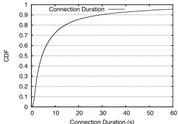
To see why the status quo is intolerable if we use open WiFi APs from moving cars, see Figure 2. It shows the CDF of the time between when the first beacon was heard from an AP and the time at which the last beacon was heard. As such, it provides an upper bound on the how long the car can obtain connectivity via the AP. The me-dian is connection lasts 4 sec, with a mean of 19 sec and standard deviation 2 sec. It is clear that a stock implemen-tation of the connectivity establishment scheme would not be able to use the majority of these potential opportunities, and even if it did, would leave very little time for actual data transfers. In Section 3, we show how QuickWifi is able to reduce the time between observing a beacon and establishing end-to-end connectivity to 366 ms on aver-age (a gain of 35× over the status quo), leaving much more time to retrieve and send data, and providing access to about 4× as many connections as a stock implementa-tion.
2.2
Proper Handling of High Loss Rates
Packet losses over the wireless link are common in our ob-served encounters, with a mean packet loss rate in excess of 20 percent. Figure 3 shows how the packet loss rate varies with time from the beginning of each connection to the end for encounters using QuickWifi that last between
0 0.1 0.2 0.3 0.4 0.5 0.6 0.7 0.8 0.9 1 0 10 20 30 40 50 60 CDF Connection Duration (s) Connection Duration
Figure 2: CDF of encounter duration. Median is 4 sec, mean is 19 sec. 0 10 20 30 40 50 60 70 0 20 40 60 80 100
Packet Loss Rate (%)
Connection Time (%) Loss Rate
Figure 3: Packet losses vs. Encounter Time. Most packet losses occur in the beginning and end of an encounter, but sustained high packet losses are common.
3 and 20 seconds. The results show that the beginning and end of a connection experience very high packet loss rates. However, even in the middle of a connection, high loss rates are to be expected.
A simple solution to this may be to establish a new TCP connection at the beginning of each encounter. However, given the high packet loss rates observed in our measure-ments, a congestion control mechanism based on end-to-end packet losses (such as most stock TCP implementa-tions) may not be the ideal solution. In addition, by dis-carding state between encounters, such a solution risks losing valuable time and bandwidth to unnecessary setup costs and packet retransmissions. To address this, we pose the Cabernet Transport Protocol (CTP), which pro-vides TCP-friendly congestion-control, reliable in-order delivery, with no connection setup overhead, and seam-less connection migration.
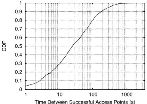
0 0.1 0.2 0.3 0.4 0.5 0.6 0.7 0.8 0.9 1 1 10 100 1000 CDF
Time Between Successful Access Points (s)
Figure 4: CDF of time between successful access point encounters.
2.3
Managing Intermittent Connectivity
The distribution of times between encounters depends on the density of open access points in the area and the speed of travel. Figure 4 shows the CDF of the time between AP encounters. The observed median time between suc-cessful encounters was 26 sec and the mean was 72 sec, heavily skewed by a small number of longer intervals. With 95% probability, a successful encounter will hap-pen within 5 minutes after the last encounter ended. Over 124 hours of driving, 10 hours were spent in successful encounters. The rest was spent scanning for open access points and attempting connections.
Given the short encounter durations, most encounters will not be long enough to complete a requested transfer, and time between encounters may be on the order of sev-eral minutes. Because existing applications and protocols are not tolerant of such delays, we either need new ap-plications designed specifically for this environment, or we need Mobile IP-like application level proxies that hide intermittent connectivity. Cabernet provides support for both types of applications. For new applications written directly against the CTP API, Cabernet provides imme-diate feedback (through OS signals) regarding when con-nectivity is available and when it disappears. This allows applications to rapidly begin transfers when connectivity appears and avoid having to implement complex applica-tion specific timeouts or connecapplica-tion polling techniques to determine if connectivity is still present.
For legacy applications supported by proxies, Caber-net provides application-specific proxy clients on the cars that intercept TCP traffic from the application, and de-liver it using CTP to an Internet based-proxy server. To keep applications from timing out, the client proxy may issue periodic heartbeats or updates to the application. The proxy server then runs the application protocol (e.g., HTTP download, FTP transfer, or IMAP session) on be-half of the car-based application, and delivers results back
Total Driving Time 124 hours
Successful Connections 6749
Distinct Successful Access Points 1401
Table 1: Summary of experimental data.
to the client proxy (which may occur several minutes later if the car has disconnected from its current access point.) Running transfers while the car is disconnected is a form of prefetching, and can dramatically reduce the overall time required for the car to complete a session if the actual server is slow or the protocol requires many long-latency round trips (as can be the case in HTTP or IMAP.)
2.4
Experiments and Data Characteristics
Before describing these components of the system in more detail, we briefly summarize summarize the data that we collected using our cab-based testbed. Table 1 summa-rizes the data set in terms of total driving time, number of connections, and number of access points observed. A typical day a number of door-to-door trips between homes as well as offices as well as several trips to and from the airport. The company also operates shuttle services be-tween various high-tech companies in the area. It is likely that some of the results reported here may look different when compared to results from private cars, which may not travel as widely and are usually not used for as long as taxis every day.
Taxis tend to spend a significant amount of time station-ary, waiting for customers. This is particularly true in our case, as the vehicles in question are hybrid cars, in which “idling” is not the issue it may be with regular cars. To account for this potential error source, we remove from our data set any waiting period (time period in which a vehicle remained stationary for more than 2 minutes).
When the car is powered off, power to the node is cut off too and data collection ends. Data collection resumes automatically some time after the car is powered back on. We define “driving time” as the time between power on and power off, minus waiting periods as defined above.
We now focus on the design of the two major compo-nents of the system: QuickWifi (which includes notifica-tions for applicanotifica-tions about intermittent connecnotifica-tions) and CTP. After describing these components in Section 3 and Section 4, we summarize the end-to-end performance of the entire system in Section 5. We briefly revisit the is-sue of supporting legacy applications through proxies in Section 6.
3
Connecting with QuickWifi
Establishing an Internet connection over a wireless AP involves several steps which in the status quo can take significant time to complete. This phenomenon is
well-known, familiar to any laptop user who has waited for his or her laptop to find and associate with an access point). The situation is exacerbated in vehicular environments be-cause of the high packet loss rates. In [2], the mean time between an in-car device discovering an AP and success-fully establishing a connection was measured to be 12.9 seconds.
Several tasks need to complete before local IP layer connectivity with an AP can be established:
Scanning: In IEEE 802.11b as specified for the U.S., there are 11 (partially overlapping) channels. Typically, clients scan by tuning to each of the available channels, lingering for at least 100 ms on each channel to listen for beacons from nearby access points. With 11 channels, this approach results in a mean delay of 600 ms between enter-ing the coverage range of an access point and discoverenter-ing it; it could be larger if the packet loss rate is high because worthy APs may not show up until multiple rounds are completed.
Authentication: The 802.11 standard mandates that
clients authenticate themselves with the AP prior to re-questing association. In an open AP, no actual authentica-tion takes place, and the access point will always answer in the affirmative.
Association: Before accepting regular payload packets, APs require stations to go through an association re-quest/response exchange. If the AP receives the request, and if the specified parameters (such as bit rates, power saving settings, etc) are acceptable, the AP will respond with an association response frame containing a success-ful status code.
DHCP discovery: In the DHCP discovery phase, the sta-tion sends a DHCP Discover request to the broadcast ad-dress. Receiving DHCP servers all respond with a DHCP Offer message. If no DHCP Offer messages are received after a fixed timeout interval (usually 3 seconds), the sta-tion resends the DHCP Discover request.
DHCP request: In the DHCP request phase, the station selects one of the potentially many received DHCP of-fers, and broadcasts a DHCP Request message, for all re-sponding DHCP servers to hear. After the selected DHCP server responds with a DHCP Acknowledgment message, the station is free to start using the IP address.
ARP request: The client sends an ARP request to the broadcast address and the gateway responds with a uni-cast. The default timeout is long (2 seconds).
There are four problems with the status quo for vehicu-lar uses. First, 13 frames need to be successfully received over the wireless channel before local connectivity is fea-sible. At high packet loss rates, this process takes a long time, particularly with ill-suited timeout values (tuned for
wired Ethernets) that are in place today. Second, the
stages are sequentially executed; each step must wait for the previous one to complete. Third, current client stacks
5 beacons lost 5 attempts failed 5 attempts failed 5 attempts failed 5 attempts failed 5 attempts failed SCANNING AUTH REQ, ASSOC REQ found non-blacklisted AP DHCP DISC DHCP REQ CONNECTED recv dhcp offer recv dhcp ack SIG OFFLINE SIG ONLINE recv auth, assoc resps
ARP QUERY PING THROUGH
recv arp reply
recv ping reply
5 retries
5 retries
5 retries
5 retries
5 retries
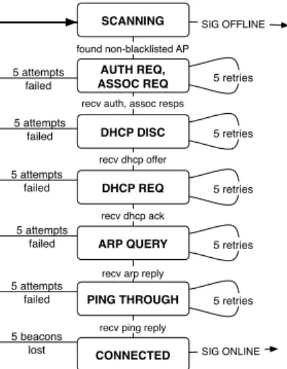
Figure 5: Connection establishment state diagram. Opti-mized for rapidly changing environments.
don’t worry about quickly noticing when end-to-end con-nectivity has been established and when it has failed, as will happen when a car moves out of range of an AP. Fourth, the scanning process assumes that each channel is equally likely, and scans round-robin. We note (as have others) that channels 6, 1, and 11 are much more com-mon, and develop an optimal scanning scheme that takes the non-uniform likelihood of encountering a channel into account.
To improve the time to establish local and end-to-end Internet connectivity, we have developed QuickWifi, a streamlined implementation that solves the above prob-lems. The implementation is a single state machine, run-ning in one process, as shown in Figure 5. Runrun-ning in one process ensures the process switching overheads are non-existent, which can be significant on 200-300 MHz embedded computers (as in our testbed), given the rate at which we switch states. The rest of this section describes the optimizations in QuickWifi.
3.1
Improved loss resilience
Authentication, association, DHCP, and ARP all include timeout/retry protocols. Retries are very likely, particu-larly in DHCP discovery and ARP request phases when broadcast messages are used. By reducing timeouts to hundreds of milliseconds (which is much longer than the typical wireless channel round trip time), rather than sec-onds (as in most implementations), we can dramatically reduce the mean connection establishment time.
In QuickWifi, the timeout period in each phase is set to 100 ms, after which the request is sent again, up to 5 times. If the 5th request fails as well, the process starts over with the scanning phase.
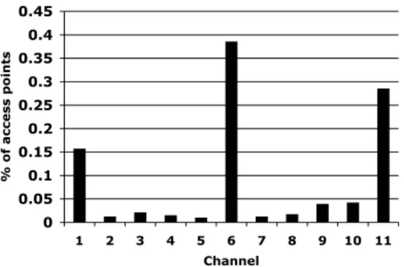
0 0.05 0.1 0.15 0.2 0.25 0.3 0.35 0.4 0.45 1 2 3 4 5 6 7 8 9 10 11 Channel % of access points
Figure 6: Unique access points with successful associa-tion, per channel.
Optimized scanning: By scanning popular channels
more frequently, we can reduce the expected channel dis-covery time. We look at this optimization in more detail in Section 3.4.
3.2
Improving parallelism
Because the authentication phase is always successful (we never associate with password protected networks), we do not need to wait for the response to our authentication re-quest. Should the authentication request be lost, the sub-sequent association request will return a failure, which re-sults in QuickWifi restarting the connection process.
3.3
End-to-end connectivity monitoring
QuickWifi includes two additional states to monitor the status of a connection.
Ping-through: Many seemingly open access points do not provide end-to-end Internet connectivity (because, for example, they require the user to register before granting end-to-end connectivity). QuickWifi uses an end-to-end ping for this task. After the connection is verified, Quick-Wifi explicitly notifies applications that Internet connec-tivity is available, through an OS signal.
Tear-down: Vehicular WiFi connections are inherently short-lived. We need to quickly discover that a connec-tion is lost, and return to the scanning phase. The tools available in current operating systems have a long time-out, and do not explicitly notify applications of connec-tion loss, leaving applicaconnec-tions to rely on timeouts of their own to discover connection disruptions. In a vehicular scenario, if we have not seen any transmissions (includ-ing beacon frames) for several hundreds of milliseconds, it is highly likely that the car has moved out of the range of the access point. In this case, we return to the WiFi scan-ning phase and explicitly notify applications that Internet connectivity has been lost, through an OS signal.
3.4
Optimal scanning strategies
Only three channels in IEEE802.11b/g are considered “or-thogonal”, free of overlap from each other: 1, 6 and 11. Users take this information into account in practice; we find that the distribution of AP channels in our data set is non-uniform and biased toward these channels. Figure 6 shows the distribution of observed APs across the 11 available channels. 83% of unique access points observed are assigned to one of the three orthogonal channels, with 38.5% on channel 6.
Given this information, what is the best scanning strat-egy that minimizes the time it takes to find a channel with an open AP present? Let N be the number of channels,
and λk, 1 ≤ k ≤ N, ∑ λk= 1 be the probability that an
ar-bitrary access point is assigned to channel k. For our
pur-poses, we assume that λk is as in Figure 6. What is the
expected time to detect an open AP that is within range? Let us start with the stationary case. Here, we are in range of an access point when we start scanning. The sim-plest policy is to scan each channel once, with equal prob-ability (the status quo). The expected number of channels
to scan is N2. A better policy would be to scan channels
in decreasing order of λk. Doing so gives a probability of
succeeding in step i given than the previous steps did not succeed,
p(i) = λk(i)
∑Nj=iλk( j)
,
where k(i) is the channel scanned at step i. Using this for-mula and the values in Figure 6, we find that the expected
time is ∑Ni=1ip(i) ∏i−1j=1(1 − p( j)) = 2.5—a speedup of
2.4× over the current scheme.
We are, however, interested in the mobile case where the client in the car is continuously scanning, and the AP comes in range at an arbitrary time, assigned to a channel according to the λ distribution. Note that since we do not know when the AP appears, simply scanning in
decreas-ing order of λkis not a good strategy. Instead, we need to
periodically scan each channel k with a period determined
by some function 0 < f (λk) <= 1. This bounds the time
between scans of channel k to d1/ f(λk)
∑Ni=1f(λi)e = d
∑Ni=1f(λi)
f(λk) e,
and the expected time to find the access point if it was
as-signed to channel k is 12∑
N i=1f(λi)
f(λk) . The overall expected
scanning time E[t] is then,
E[t] = N
∑
k=1 λk 1 2 ∑Ni=1f(λi) f(λk) =1 2 N∑
i=1 f(λi) ! N∑
k=1 λk f(λk) .Applying the constraint that ∑i1/ f (λk) = 1 (because
the client is work-conserving and always scanning), we
would like to determine what values of f (λk) achieves the
minimum.
Using Lagrange multipliers, it is easy to see that the
expected time is minimized by f (λj)/ f (λk) =
p λj/λk.
0 0.1 0.2 0.3 0.4 0.5 0.6 0.7 0.8 0.9 1 0 200 400 600 800 1000 1200 1400 CDF
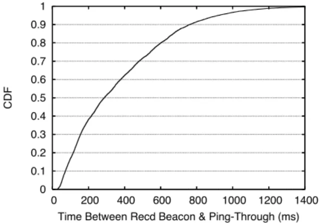
Time Between Recd Beacon & Ping-Through (ms)
Figure 7: QuickWifi speeds up connection establishment. CDF of connection delay when using QuickWifi. Median = 287 ms, mean = 366 ms. 0 0.02 0.04 0.06 0.08 0.1 0.12 0.14 ASSOC
DHCPDISC DHCPREQ ARPQUERY PINGTHRU
Figure 8: Mean time spent in the various phases of con-nection establishment.
Implementing this scheme is easy: give a weight to
each channel k equal topλk. Then, scan channels using
weighted fair queuing [3], or any packetized processor sharing discipline that is work-conserving. The scan order is determined by the schedule produced. For example, the following schedule of length 25 achieves E[t] = 3.64:
6, 11, 9, 2, 6, 1, 11, 10, 6, 3, 1, 11, 6, 4, 9, 11, 6, 1, 5, 10, 6, 11, 7, 1, 8, about 40% better than the naive scanning approach.
3.5
QuickWifi performance
We now turn to the performance of the connection es-tablishment process. For each successful connection, we measure the time between when the car initiated the au-thentication phase, and when QuickWifi reported a suc-cessful connection to the higher layers. Figure 7 shows the CDF of connection establishment times. With a mean connection establishment time of 366 ms, and a median of 287 ms, QuickWifi achieves a dramatic 35× speedup over the 12.9 seconds reported by previous measurements [2] (and confirmed by us).
0 0.1 0.2 0.3 0.4 0.5 0.6
DHCPDISC DHCPREQ ARPQUERY PINGTHRU CONNLOSS
Figure 9: Connection Failures in QuickWifi. Bars indicate percentage of connection failures at various phases.
QuickWifi spends 366 ms on establishing a connection, but how is this time spent? Figure 8 shows the mean time spent in each of the phases, for all connections that even-tually succeeded. DHCP dominates the delay incurred, with a total of 197 ms spent on the two DHCP phases. The reason is that both the DHCP discover and the DHCP request packets are sent to the broadcast address. Such packets don’t benefit from link-layer ACKs and retrans-missions, which means that this stage takes a long time to complete. QuickWifi’s quicker retransmissions help com-pared to the status quo, but it isn’t the same as fast link-layer recovery.
ARP queries are also sent to the broadcast address. However, we believe the shorter time spent on ARP queries can be explained by a filtering argument: once both DHCP phases have completed, we find that the con-nection quality is significantly improved given success in the two DHCP phases. In addition, ARP queries are short compared to DHCP packets (< 30 bytes of payload, no IP header, compared to 200 bytes), resulting in a lower probability of packet loss. The relatively short time taken for ping-through (40 ms) is consistent with the round-trip time to MIT from locations in the Boston area.
The shorter timeouts used in QuickWifi lead to faster connection times. However, it could also lead to unnec-essary connection establishment failures. Figure 9 shows the distribution of connection failures, for all access points
that allowed QuickWifi to associate. CONNLOSS
in-dicates those connections that were successfully estab-lished, and subsequently failed as the car moved out of range of the access point.
We note that the vast majority of failures happen in the DHCP phases. There are several possible contributing factors to this. First, some DHCP servers may be unable to respond before QuickWifi times out and restarts the pro-cess. Given the relatively short mean time reported for the DHCP Discovery phase in Figure 8, it appears that few DHCP servers require more than 100 ms to process a
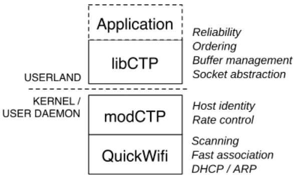
re-QuickWifi modCTP libCTP Application Reliability Ordering Buffer management Socket abstraction Host identity Rate control Scanning Fast association DHCP / ARP USERLAND KERNEL / USER DAEMON
Figure 10: Layering of Cabernet software components.
quest. It is possible that two types of DHCP servers exist, those that generally process a request in less than 100 ms, and those that generally process a request in more than 500 ms. We did not investigate this possibility further. Second, some access points may not offer DHCP services. Given the large number of failures in the DHCP Request phase, it appears that at least a large fraction of DHCP failures are due to other causes than a lack of DHCP ser-vices at the access point. And third, poor channel quality is in all likelihood the biggest culprit. With sufficiently poor channel quality, an encounter never makes it past the DHCP phases, and thus the later phases are never at-tempted.
From these results, we conclude that in the major-ity of cases, QuickWifi establishes connections where such connections are feasible. Additional experimenta-tion with varying DHCP timeouts and addiexperimenta-tional retries in the DHCP phases may offer further performance im-provements.
4
The Cabernet Transport Protocol
CTP has two parts: a kernel module, modCTP, and an application library, libCTP, as shown in Figure 10. Pe-riodic end-to-end acknowledgments (ACKs) sent every
ack interval seconds from the receiver allow the
proto-col to provide a reliable, ordered stream of packets to the application (see Section 4.2). The novel part of CTP is its rate control protocol implemented in modCTP, as de-scribed below. Communication between libCTP and mod-CTP is done with sockets, transparent to the application.
4.1
Congestion control with modCTP
Each host maintains a single instance of modCTP to the destination host, controlling the total rate and sharing it between all applications flows between the two hosts. modCTP handles the reception and transmission of pack-ets through QuickWifi, signaling each registered applica-tion when it has a packet to deliver or is ready to transmit the next packet.
Because the baseline packet loss rate in the vehicular environment over the wireless link is much higher than over the typical Internet path even including the WiFi link-layer retransmissions (Section 2, simply running TCP would not perform well. What we would like is a scheme that reacts to packet losses on the Internet path by per-forming correct rate control, but which recovers from all packet losses wherever they might occur. For congestion control over the wireless hop, we rely on the channel ac-cess mechanisms implemented on the wireless LAN. This problem is non-trivial because we don’t control the access point or the gateway between the wired and wireless net-works (so solutions that run an agent at the access point or split the TCP connection don’t apply). Moreover, it needs to run well for both for transfers from an Internet host to a car and for transfer from the car to Internet hosts.
For transfers from Internet hosts, CTP sends periodic probes to the access point (or last IP hop before the node in the car). The assumption is that this path does not in-clude the high-loss wireless link. Using these probes, the sender assesses the packet loss rates and round-trip time over the wired path. It combines this information with in-formation about the number as well as inin-formation about the number of packets acknowledged from the receiver between probe responses to dynamically adjust its trans-mission rate. We first discuss choices for probes, and then discuss the rate adjustment scheme.
4.1.1 Probes
The choice of suitable probe traffic depends on its ability to elicit responses from an unmodified access point (or last-hop gateway), incur relatively low traffic overhead, and work in the presence of NATs and common firewall configurations. We use three methods, trying each one in turn:
1. A 1500-byte TCP packet to a randomly selected, high-numbered port on the access point. Because the TCP packet most likely does not belong to any TCP session known to the AP, it will respond with a small TCP RST message. The CTP sender uses this mes-sage as an implicit ACK.
2. If the AP does not send TCP RST messages, the CTP sender uses a probe packet that is identical to a reg-ular payload packet, but with the IP header’s time-to-live (TTL) field set to one less than the number of hops to the car. CTP estimates the number of hops by looking at the remaining TTL in packets received by the wireless client, and sending that value back to the Internet host as part of CTP’s end-to-end ACKs. If the path length estimate is correct, the TTL will expire when the packet reaches the access point, and the access point will respond with an ICMP “time ex-ceeded” message, which we use as an implicit ACK. Because Internet routes can vary, the sender adjusts
the path length estimate on every received acknowl-edgment.
3. The above two forms of probes are attractive because the TCP RST and ICMP messages received in return consume negligible bandwidth. However, if neither form of probe succeeds, the sender uses a 1500-byte ICMP ECHO packet to the AP as the probe. If the access point is ICMP-enabled, it will respond with a 1500-byte ICMP response. This is somewhat waste-ful of uplink capacity, but acceptable given that probe packets make up a small fraction of the overall data transfer.
If none of these techniques produces a response from the access point, modCTP relies on observed end-to-end packet losses for rate control, essentially reverting to TCP behavior.
For transfers from the car, the sender receives imme-diate feedback about wireless losses through MAC layer ACKs and can ignore them without using probes.
4.1.2 Rate adjustment
Using the end-to-end feedback provided by periodic CTP ACKs and the probe feedback, CTP continuously adjusts the transmission rate for each destination. The main goals in the adjustment are to ensure that the rate reduction re-acts to congestion and that the increase/decrease methods are roughly friendly to TCP traffic. One can use sev-eral possible schemes, including equation-based conges-tion control (EBCC) [5]. Because we want a scheme that works well for short connections, EBCC isn’t appropri-ate without modification. We want a scheme that mimics multiplicative increase for short connections (and at the beginning of a new connection), but which moves to a scheme consistent with additive increase once it has been active for a while.
The CTP sender considers increasing its rate each time it gets an ACK. If the CTP ACK indicates that no payload packets were lost during the ack interval period, the new rate for a long-running CTP connection is computed as
rate← rate +ack interval
rtt2 . (1)
This increase rule is similar to TCP’s additive increase, where TCP increases the window by 1 packet per RTT (actually, 0.5 packets with delayed acks but we ignore
that here). Therefore, in one RTT (measured in
sec-onds), TCP’s rate increases from W /RTT packets/s to (W + 1)/RTT packets/s, where W is the window size in packets. The increment in rate is 1/RTT packets/s, which is made every RTT seconds. Hence, in ack interval sec-onds, the rate should increase by the amount shown above. CTP considers reducing its rate every time a new probe packet is sent. If the previous probe packet got no
re-sponse, the new rate is computed as
rate← max(rate · (1 −2 · lost payload
sent payload , rmin), (2)
where sent payload and lost payload are the values from the most recent acknowledgment. (If none of the three probe mechanisms provide useful feedback, rate de-creases are computed on each received end-to-end ACK.) The reason for the somewhat unconventional formula above is that CTP receives congestion feedback infre-quently (once every second from the probes) about con-gestion. As such, simply reducing the rate by one-half may not be good enough if the packet loss rate observed on the wired connection is high because our sending rate is too high. We found that in this case, the rate reduc-tion must take the actual loss rate over the wired path,
lost payload
sent payload, into account. However, just reducing the rate
to the current rate times the packet success rate isn’t good enough because that might continue to keep the path sat-urated; we need a more aggressive reduction that allows other connections to get packets through. Therefore, we (somewhat arbitrarily) dock the sending rate by doubling
the reduction. Finally, the rminterm is a basic minimum
rate (200 kbit/s) for CTP connections (obviously, it is con-figurable).
We don’t claim that this increase/decrease rule is the best one to use, but have found from numerous experi-ments that it performs well in practice and interacts well with TCP.
4.2
libCTP
libCTP exposes a reliable socket API to the application. The main difference is that a CTP connection does not break when the underlying connection disappears. In-stead, CTP connections migrate seamlessly across access points, through the use of unique host identifiers in the
CTP header.1
Reliable transfers are achieved through the use of a large send and receive buffers. An outgoing message is divided into packet size chunks, each of which is assigned a chunk sequence number. Each ACK contains a bit-mask indicating what chunks are still missing. Whenever modCTP signals its readiness to receive another packet, libCTP retransmits one of the missing chunks (accounting for possible packet reordering), until no missing chunks remain. When a transfer is complete, control is returned to the application. Alternatively, if the non-blocking API is used, the application is signaled upon completion.
4.3
CTP vs TCP Performance
To determine the utility of the rate control measures in-troduced in CTP, we compare the throughput achieved by
1When and where Mobile IP is available, this aspect of CTP can be
0 0.1 0.2 0.3 0.4 0.5 0.6 0.7 0.8 0.9 1 0 200 400 600 800 1000 1200 1400 1600 1800 2000 CDF Throughput (Kbit/s) CTP TCP
Figure 11: CDF of encounter-averaged throughput
achieved using CTP and TCP respectively.
0 0.1 0.2 0.3 0.4 0.5 0.6 0.7 0.8 0.9 1 0 0.5 1 1.5 2 2.5 3 3.5 4 CDF
Total Downloaded MBytes CTP TCP
Figure 12: CDF of downloaded bytes per access point en-counter.
CTP to TCP for downloads to cars. The TCP implemen-tation used was the default settings in Linux 2.6.17.13,
with SACK enabled. Figure 11 shows the CDF of
the encounter-averaged throughput achieved with CTP and TCP. We note that the measured median throughput achieved by CTP is approx. 2× that of TCP. The mean CTP throughput, 94 kB/s was somewhat less than 2× the TCP throughput of 51 kB/s.
The total number of bytes downloaded in an encounter is a function of the throughput as well as the duration of the encounter. Thus, throughput and bytes downloaded need not have a one-to-one correspondence. Figure 12 shows the CDF of the number of bytes downloaded per encounter. We note that the median CTP download is ap-proximately 2× the median TCP download. However, the mean CTP download of 2438 kB/s is only 35% higher than the mean TCP download of 1860 kB/s.
The explanation for this phenomenon is simple: long duration encounters have significantly lower packet loss rates than short duration encounters. Figure 13 plots the packet loss rate vs. encounter duration. It is clear that the
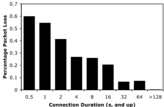
0 0.1 0.2 0.3 0.4 0.5 0.6 0.7 0.5 1 2 4 8 16 32 64 >128
Connection Duration (s, and up)
Percentage Packet Loss
Figure 13: Avg. packet losses vs. encounter duration. Longer encounters on average exhibit lower packet drop rates. 248.04 292.72 434.32 0 100 200 300 400 500 600 TCP alone TCP / CTP TCP / TCP Measured TCP Throughput (kB/s)
Figure 14: Mean throughput achieved by TCP in three scenarios: Alone, competing with a CTP flow, and com-peting with another TCP flow. Error bars indicate stan-dard deviation.
majority of the very high loss rates are contributed by rel-atively short-lived connections, with relrel-atively low (5%) loss rates for encounters 32 seconds and longer. Thus, on long duration encounters, TCP is able to achieve nearly the same throughput as CTP. This combination of long du-ration and high throughput explains the disparity between the mean throughput and download values.
4.4
Interacting with TCP
To evaluate the “TCP friendliness” of the CTP rate adap-tation algorithm, we ran a set of experiments from inside a home. Wireless packet losses were minimized by plac-ing the node nearby the access point. We then measured the downstream throughput of one TCP flow, under three different conditions: a) the measured TCP flow was the only active flow on the local network. b) the measured TCP flow was competing with a downstream CTP flow. c) the measured TCP flow was competing with a second downstream TCP flow.
In all cases, the measured TCP flow was established 20 times, each performing a 10 MB download. In cases b)
0 0.2 0.4 0.6 0.8 1 0 5 10 15 20 CDF
Expected Response Time (min) 1 MB transaction 100 kB transaction 10 kB transaction
Figure 15: CDF of expected transaction time, given sev-eral transaction sizes.
and c), the competing flows were established before the start of the first measured TCP flow, and ended after the end of the last TCP flow. In case b), we manually verified that the CTP flow was saturating the link before the start of the first TCP flow.
Figure 14 illustrates the result of these experiments. We note that the measured TCP flow achieves more somewhat higher throughput when competing with CTP than when it is competing with another TCP flow. In addition, the standard deviation is lower when the measured TCP flow is competing with CTP than when it is competing with another TCP flow.
5
End-to-End Performance
Having established the performance of QuickWifi and CTP in isolation, we now turn to the overall performance of the implemented system. The experiments described below seek to answer the following key questions and ex-plain observed performance:
1. What is the expected time between a request for in-formation, and the retrieval of the desired response? 2. Given WiFi conditions in the Boston area, what is the expected time-averaged throughput of a Cabernet-equipped moving vehicle?
5.1
Expected Transaction Time
For applications that react to external stimuli, such as passing a landmark, a timer expiring, or a user action, the expected time taken to complete a network transaction is of interest. We envision a usage scenario where an appli-cation requests a download of a given size, at an arbitrary time. We then compute, for every second of driving time, the time it would take Cabernet to complete the download.
Figure 15 shows the expected response time tr, for a
varying transaction size s. The median response time for a small (10 KB) request was 2 minutes, and the mean was 5 minutes. Typical requests of this nature may
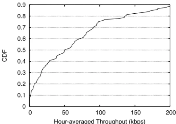
0 0.1 0.2 0.3 0.4 0.5 0.6 0.7 0.8 0.9 0 50 100 150 200 CDF Hour-averaged Throughput (kbps)
Figure 16: CDF of the expected number of bytes down-loaded, per hour of driving.
clude traffic and weather updates, requesting driving di-rections, polling RSS feeds, and checking for new email. For larger transfers, such as downloading a full web page, large emails with attachments, or a 1 minute audio clip at good mp3 quality, we consider a 1 MB request. The me-dian time for such requests was 4 minutes, and the mean time was 9 minutes.
Thus, while Cabernet is not suitable for a fast-paced browsing session, moderately interactive usage is feasible. Moreover, Cabernet is well suited to applications which performs periodic background updates as often as every few minutes.
5.2
Expected long-term Throughput
For less time-sensitive applications, such as podcasts, pre-dictive caching of frequently visited websites, or back-ground file synchronization, the metric of interest is total download capacity, rather than transaction time.
We divide up the driving time of each car into one-hour-long segments, and compute the total download through-out each time segment. Figure 16 shows the CDF of per-hour downloads. The median throughput was 50 kbit/s, and the mean was 87 kbit/s, or 38 Mb/h. Thus, pend-ing further increases in open WiFi availability, Caber-net is suitable for applications requiring modest down-load capacity. Suggested applications include automatic GPS map updates, predictive caching of popular web con-tent, smaller media subscriptions, including music and pictures, etc.
5.3
Impact of WiFi Rate Selection
In the 802.11a/b/g family of protocols, the sender of a packet decides what wireless bit rate to send the packet at. Hence, when downloading files to cars in Cabernet, the access point essentially is in complete control of the bit rate. The bit-rate adaptation protocol used by most ac-cess points is optimized for stationary users connecting
Bit Rate vs. Success Rate 0 0.1 0.2 0.3 0.4 0.5 0.6 0.7 0.8 0.9 1 1 2 5.5 11 18 24 36 48 54 Bit Rate (Mbit/sec)
Probabilit
y of Success
Pr(Succ) Pr(Succ | Prev Fail) Pr(Succ | Prev Succ)
Figure 17: Probability of a successful packet transmis-sion, for varying transmission rates.
over relatively low loss rate links and is typically quite aggressive about reducing the bit rate when a loss occurs. One common protocol (ARF) increases the bit rate by one level whenever k or more successful transmissions occur, and decreases the bit rate when 1 or 2 frames are lost. Due to the high loss rates in Cabernet, using such a rate adap-tation mechanism is doomed to degrade degrade to the lowest possible (1 Mbit/sec) transfer rate. This slow trans-fer rate is consistent with the relatively low per-encounter throughput reported in Figure 11.
To determine whether a different bit rate adaptation strategy might work better, we performed a series of ex-periments to measure loss rates from vehicles at differ-ent bit rates. 802.11b supports 4 wireless transmission rates, 1, 2, 5.5 and 11 Mbit/sec, which correspond to a particular choice of modulation and error correcting code. 802.11g adds several more rates, ranging from 6 through 54 Mbit/sec. During an encounter, we period-ically sent bursts of 10 frames to the access point, and recorded whether an acknowledgment was received.Each frame sent was sent at a rate chosen uniformly at random from the supported rates advertised by the access point. We did not include the 802.11g rates 6, 9 and 12 Mbit/sec, after early experiments showed that they were not compet-itive with the 802.11b rates 5.5 and 11 Mbit/sec.
Figure 17 shows the results of this experiment. For each rate, the overall probability of success is shown, as well as the probability of success given that the previous attempt (at any rate) was a success or failure.
It is immediately apparent that 802.11b transmissions are much more likely to succeed than the faster 802.11g rates. However, somewhat surprisingly, the difference be-tween rates 1 through 11 is small. We speculate that this, in part, could be due to the longer transmission time of a packet sent at 1 Mbit/s, combined with the quickly chang-ing channel conditions in vehicular WiFi. Our
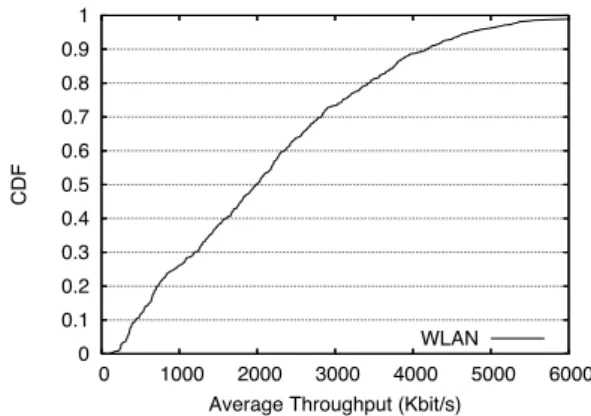
0 0.1 0.2 0.3 0.4 0.5 0.6 0.7 0.8 0.9 1 0 1000 2000 3000 4000 5000 6000 CDF
Average Throughput (Kbit/s) WLAN
Figure 18: CDF of average throughput experienced over the course of an encounter, using a fixed 11 Mbps rate.
ments suggest that using 1 Mbit/sec is probably never a
good choice in Cabernet2. From this data, it’s unclear if
802.11g rates are ever a good idea – though they succeed 2-3 times less often, rates are enough high that they may still offer an overall performance gain.
Based on the above findings, we implemented a “fixed 11 Mbps” rate selection strategy on our taxi testbed, and measured the achieved throughput from the cars, to en-countered open access points.
We measure WLAN throughput by periodically send-ing a “train” of 10 large (1500-byte) back-to-back pack-ets to the access point. Each packet is individually and immediately acknowledged by the access point, in accor-dance with the IEEE 802.11 MAC protocol. We record time stamps for when the packet train transmission started
(ts), and when each acknowledgment, or transmission
fail-ure notification, was received (ti
a). Let l be the number
of successfully acknowledged packets. The instantaneous throughput is then computed as
bytes trans f erred
time taken =
10 × 1500 t10
a − ts
.
Figure 18 shows the CDF of the mean throughput achieved over the duration of an encounter. The overall mean throughput was 2.2 Mbit/s. The mean is lower than the 11 Mbit/s channel rate for a number of reasons. First, regular 802.11 overhead brings the original 11 Mbit/s down to about 6 Mbit/s. Add to that an increased back-off time, resulting from packet losses (which in 802.11 are presumed to be due to collisions) and potential contention with other users, and the expected rate drops even further. Nevertheless, 2.2 Mbit/s is significantly higher than the 751 kbit/s mean CTP throughput reported in Section 4. To ensure that the increased throughput on the wireless link would result in an end-to-end performance increase,
2Of course, it is possible that loss rates are not symmetric, but we do
we measured the available bandwidth from MIT to 424 encountered access points. We found that 75% of con-nections had available bandwidth in excess of 2.2 Mbit/s, with a mean well over 4 Mbit/s. Thus, even with improved rate selection at the access points, the Internet connection is unlikely to be a bottleneck. We conclude that modify-ing the rate adaptation algorithm used in access points is likely to result in a performance improvement of approxi-mately 3×.
6
Deployment Issues
Given the encouraging performance observed in our ex-periments, we now discuss possible larger-scale deploy-ment paths for Cabernet. There are several non-technical challenges to overcome. First, to increase Cabernet capac-ity and performance, incentives to encourage access point owners to “open up” are needed.
A recent and very interesting model is that pioneered by Fon [6]. Here, users open their access point to all Fon users that also open theirs. This model has been widely embraced, and is actively supported by established Inter-net service providers including British Telecom and Time-Warner. In addition to privately operated access points, recent initiatives in municipal WiFi, and nationwide WiFi networks such as those operated by T-Mobile and Star-bucks offer widespread coverage which could could also be incorporated into the Cabernet network.
6.1
Legacy Application Support
A second practical issue relates to support for legacy plications, since most interesting Internet content and ap-plications are served exclusively using TCP/IP. Not only are end-points required maintain a constant IP address for the duration of an application session, they are frequently required be continuously available. For example, if a con-nection is lost while a browser is downloading webpage, the content that was not yet downloaded will time out and result in error messages. Similarly, during an FTP file transfer, or an IMAP mailbox update, timeouts break ses-sions and require reconnecting.
To address this problem, we propose to support well-known applications,such as regular web browsing, file downloads, and email management, by application
spe-cific, transparent proxies. Similar proxies exist today
(e.g.,Squid [19]), and are widely deployed for perfor-mance, security, monitoring and confidentiality purposes. Less well-known applications are supported through a straight-forward translation layer, which terminates local TCP connections at the car, and tunnels the data through CTP to an Internet based CTP-to-TCP proxy. Such ap-plications may experience performance difficulties due to the intermittent connectivity in Cabernet.
7
Related Work
The current approach to delivering information to moving cars is to use a wide-area cellular system such as GPRS, 3G, EVDO, etc. In general, these approaches cost tens of dollars per month in many parts of the world, which makes them too expensive for a variety of “lower end” mobile information services. Even if the cost weren’t an issue, the fundamental capacity of Cabernet is much higher than current cellular networks: given enough ac-cess points, the high link speed and intense spatial reuse of WiFi cannot be matched by any cellular system.
However, Cabernet was not designed to provide con-tinuous connectivity. The purpose of this study was sim-ply to thoroughly investigate the feasibility of an intermit-tently connected network of moving cars and open access points. With Cabernet, we do not propose to replace cel-lular data services, but merely to complement them.
The performance of pockets of short-range, possibly intermittently available network connectivity have been studied in previous work [15, 16, 2]. This past work has established that it is possible to use 802.11 networks to provide connectivity in cars, and looked at the transmis-sion range and degree of connectivity in both in controlled settings and as deployed in current urban environments.
Several projects have studied the problem of inter-mittently connecting from cars or other mobile devices
to the Internet. In the Infostations [7, 12, 9, 18]
project, researchers proposed a model where “islands” of connectivity—envisioned to be wireless networks pro-vided by home or commercial users (similar to 802.11 to-day) – are encountered by nodes moving throughout an area. These papers used analytical models and simula-tions to study quessimula-tions of capacity, routing, caching, and data transport.
Ott and Kutscher [16, 15], in the Drive-thru Internet project, use controlled experiments with a single car driv-ing past a sdriv-ingle access point to measure the range and connectivity of connections in an intermittent network. Our previous work on the CarTel project [8], investi-gated general architectures for mobile sensor networks, with a focus on intermittently connected automobiles; this work did not address network performance issues, such as optimized association, scanning, or transport protocols. In [2], measurements were presented illustrating the ex-tent to which wireless access points deployed in cities can be used as an uplink network for moving cars. This paper focused only on upload performance, and did not propose an optimized network architecture, although it did iden-tify several of the performance problems that motivated the work in this paper.
More generally, a variety of work on delay tolerant net-works (e.g., [4, 10, 11, 17, 20, 1, 13]) has studied archi-tectures, routing, forwarding, and analysis of intermittent
and high-delay networks. These systems are typically not focused on providing access for mobile nodes to the pub-lic Internet but rather on routing from intermittently con-nected nodes to other nodes or the Internet. In contrast, our focus is not on routing – we assume that mobile nodes are just a single hop from well-connected, fixed infras-tructure – but on maximizing the utility of that single hop.
8
Conclusion
This paper described Cabernet, a content delivery network for delivering data to moving vehicles. Cabernet uses WiFi access points for network connectivity, which do not always provide continuous end-to-end network connectiv-ity to the Internet. This disconnectivconnectiv-ity presents three key challenges: first, existing wireless networking tools can take a long time to establish connectivity, making it hard to exploit short connections from moving vehicles; sec-ond, existing transport protocols like TCP don’t handle the high loss rates that occur as cars move in and out of range of access points; third, existing applications don’t tolerate long periods of disconnection.
We added features in Cabernet to address all of these issues, and built a taxi-based testbed that we used to eval-uate its performance. To reduce connection time, we built QuickWifi, an optimized and integrated collection of tools for establishing connections with wireless access points. It is able to connect in just 366 ms, offering a 30-fold improvement over the 12 s connection times reported in prior work. It also provides features that notify applica-tions when connectivity appears or disappears, simplify-ing application design. To improve network transfers, we proposed CTP, a transport protocol specifically optimized to handle high loss rates; rather than assuming that most losses are due to congestion (as is done in TCP), it treats losses on the wired and wireless channels differently, and measures them separately. CTP is able to achieve dou-ble the throughput of TCP, with mean throughput of 800 kbit/s when connectivity is present. Taken together, these features mean that in end-to-end experiments, Cabernet is able to achieve a throughput of 38 megabytes per hour, or average throughput over an hour of 87 kbit/s.
References
[1] N. Bansal and Z. Liu. Capacity, delay and mobility in wire-less ad-hoc networks. In INFOCOM, 2003.
[2] V. Bychkovsky, B. Hull, A. K. Miu, H. Balakrishnan, and S. Madden. A Measurement Study of Vehicular Internet Access Using In Situ Wi-Fi Networks. In 12th ACM MO-BICOM Conf., Los Angeles, CA, September 2006. [3] A. Demers, S. Keshav, and S. Shenker. Analysis and
Sim-ulations of a Fair-Queueing Algorithm. Internetworking: Research and Experience, V(17):3–26, 1990.
[4] K. Fall. A delay-tolerant network architecture for chal-lenged internets. In Proc. ACM SIGCOMM, pages 27–34, 2003.
[5] S. Floyd, M. Handley, J. Padhye, and J. Widmer. Equation-Based Congestion Control for Unicast Applications. In Proc. ACM SIGCOMM, pages 43–54, Stockholm, Sweden, Sept. 2000.
[6] FON home page. http://en.fon.com/.
[7] D. Goodman, J. Borras, N. Mandayam, and R. Yates. In-fostations: A new system model for data and messaging services. In Proc. IEEE Vehicular Technology Conference, pages 969–973, May 1997.
[8] B. Hull, V. Bychkovsky, Y. Zhang, K. Chen, M. Goraczko, E. Shih, H. Balakrishnan, and S. Madden. CarTel: A Dis-tributed Mobile Sensor Computing System. In Proc. ACM SenSys, Nov. 2006.
[9] A. Iacono and C. Rose. Bounds on file delivery delay in an infostations system. In Vehicular Technology Conference, 2000.
[10] S. Jain, K. Fall, and R. Patra. Routing in a Delay Tolerant Network. In ACM SIGCOMM, 2004.
[11] P. Juang, H. Oki, Y. Wang, M. Martonosi, L. Peh, and D. Rubenstein. Energy-efficient computing for wildlife tracking: Design tradeoffs and early experiences with ze-branet. In Proc. Architectural Support for Programming Languages and Operating Systems, October 2002. [12] U. Kubach and K. Rothermel. Exploiting location
informa-tion for infostainforma-tion-based hoarding. In MOBICOM, pages 15–27, 2001.
[13] J. Lebrun, C.-N. Chuah, D. Ghosal, and M. Zhang. Knowledge-based opportunistic forwarding in vehicular wireless ad hoc networks. In IEEE Vehicular Tech. Conf., pages 2289–2293, 2005.
[14] U. Lee, B. Zhou, M. Gerla, E. Magistretti, P. Bellavista, and A. Corradi. Mobeyes: smart mobs for urban mon-itoring with a vehicular sensor network. IEEE Wireless Communications, 13(5), Oct. 2006.
[15] J. Ott and D. Kutscher. Drive-thru Internet: IEEE 802.11b for Automobile Users. In INFOCOM, 2004.
[16] J. Ott and D. Kutscher. A Disconnection-Tolerant Trans-port for Drive-thru Internet Environments. In INFOCOM, 2005.
[17] A. Seth, P. Darragh, S. Liang, Y. Lin, and S. Keshav. An Architecture for Tetherless Communication. In DTN Work-shop, 2005.
[18] T. Small and Z. J. Haas. The shared wireless infostation model: A new ad hoc networking paradigm (or where there is a whale, there is a way). In MOBIHOC, pages 233–244, 2003.
[19] Squid Web Proxy Cache. http://www.squid-cache.org/. [20] W. Zhao, M. H. Ammar, and E. W. Zegura. A message
ferrying approach for data delivery in sparse mobile ad hoc networks. In MobiHoc, pages 187–198, 2004.