** 4 * * 4 * * 4> * 4 4) 4 *
I
++ 4 44 4LSI E -Y 24 4XM 4ITLLTO -ETRUSPRTO FO4 *by
*,
T
ee o
*eesnadX
4ascuet nttt fTanlg ,.ula Eniern4Dprmn*otatN.A
3-,24
*a
16 16
Ju4 198 MY916
UNCLASSIFIED
AMMONIA DISTILLATION FOR DEUTERIUM SEPARATION
by
G. T. Petersen and M. Benedict
Massachusetts Institute of Technology
Nuclear Engineering Department
Contract No. AT (30-1)2249 May 16, 1960
July, 1958 - May, 1960
UNCLASSIFIED
Distribution
A.E.C. New York Operations Office
A.S. Friedman. A. E. C. Washington
Nuclear Engineering Department, M. I. T.
Industrial Liaison Office, M. I. T.
M. Benedict J. E. Bigelow
Contractors John Brown
W. P. Drews W. Hinkle M. P2. Kalman B. Lazard, French A. E. C. P. Lualdi J. Moss J. Neill G. T. Petersen
D. F. Stedman, National Research Labs., Canada
Total Distribution No. of Copies 8 2 10
50
1 1 19
90
The contents of this report have been submitted by
Mr. G. T. Petersen to the Massachusetts Institute of Technology
in partial fulfillment of the requirements for the degree of Doctor
of Philosophy.
-ii
-"AMMONIA DISTILLATION FOR DEUTERIUX SEPARATION"
by
GERALD THORNTON PETERSEN
Submitted to the Department of Nuclear Engineering on May 16, 1960 in
partial fulfillment of the requirements for the degree of Doctor of Philosophy in Nuclear Engineering.
ABSTRACT
The relative volatility or separation factor for deuterium enrich-ment in ammonia distillation was measured at several pressures and
deuterium concentrations. Over the range of pressure (250 mm - 760 mm Hg.) and the range of composition 0410 - 0.58 mole fraction deuterium, the
measurements are adequately expressed by the following equation:
In (a) - (0.0395 + 0.0004) - (0.0128 t 0.0029) (x - 0.424)
-
(0.01246
t
0.00065) (In
7
Hg.
a - separation factor
x - system pressure mm Hg.
x - liquid composition, mole fraction deuterium.
It is interesting to note that a dependence on the composition was observed. Although this is not predicted by the normal method of cal-culating the separation factor from the vapor pressure ratio
its existence has been postulated due to the asymmetry of the partially
deuterated ammonia molecule. However, the magnitude of the separation
factor as well as its dependence on pressure were in good agreement with the vapor pressure ratio predictions. (a - 1.042 at 1 atm.)
The knowledge of this information is very helpful in predicting costs
of heavy water production by the ammonia distillation process. It has
been stated by others, that the ammonia distillation process of heavy water production would be competitive with other developed methods only if the actual separation factor was at least 1.062 at low deuterium
con-centration. Unfortunately, the measurements do not indicate that the
separation factor at low deuterium composition differs greatly from the
vapor pressure prediction. (a - 1.042)
Deutero-ammonia was synthesized by isotopic exchange between natural ammonia and heavy water. Equilibrium determinations were made using an Othmer still, modified for low temperature operation, and a concentric tube fractionating column. The ammonia samples were analyzed for deuterium con-tent by converting them to water by flow through hot copper oxide, followed by a differential density determination using the falling drop method.
Thesis Supervisor: Professor Manson Benedict
Acknowledgement
The authors *ish to thank the following men who have been of
invaluable help in performing this work; Mr. John Neill for his assistance and advice in the early stages of the investigations and
Messrs. William Hinkle, John Moss, and Paul Lualdi for their untiring
efforts in taking experimental measurements. The financial support
of the U. S. Atomic Energy Commission is acknowledged with gratitude.
- iv -TABLE OF COTENTS
Page
I.II.
III.
Iv.
V. Conclusi-ons
I.
Recommendations
IntroductionApparatus and Procedure
A. Single-Stage Equilibrium Devices
B. The Equilibrium Still'
C. Multiple-Stage Fractionating Devices
D. Analysis for Deuterium Content E. Conversion of Deuterated Ammonia to
Dauterated Water
F. Manufacture of Deuterated Ammonia
Results
Discussion of Results
A. Correlation of Data
B. Effect of Results on the Economics of Heavy
Water Production
C. Accuracy (Sources of Error)
1. Single-stage measurements 2. Sampling and conversion
3. Analysis
4. Multi-stage column
D. Statistical Evaluation of Data
1
9
11
19
31
44
55
60
7273
73
74
75
76
7879
VII. Appendix
A. Detailed Procedure
1. Equilibrium still 81
2. Column 09
3. Analysis 95
B. Calibration and Rplated Measurements
1. Column calibration-deuterated ammonia
(Graph 8) 102
2, Falling drop analysis - calibration
(Graph 9) 102
3.
Column calibration - nheptane-methyl-cyclohexane system (Graph 10) 105
4.
Refractive index analytic calibration forn-heptane-methylcyclohexane (Graph 11) 107
-5. Thermocouple calibration (Graph 12) 107
6. Memory measurements of conversion system 110
7. Ammonia solubility of halogenated
Kel-F oil 112
8. Falling drop temperature coefficient 113
9. Effect of deuterium composition on column
stages 115
C. Associated Apparatus and Procedure
1. Pressure control system 117
- vi
-3.
Copper oxide preparation 1194. Standard sample preparation 120
D. Data and Calculated Values
1. Single-stage equilibrium data (Table 4) 122
2.
Summary of the single-stage measurements
(Table 5) 155
3. Weighted least square analysis of
single-stage equilibrium data (Table 6) 156
4. Concentric-tube column data (Table 7) 161
5.
Column calibration with systemn-heptane-methylcyclohexane (Table 8) 173
E. Sample Calculations
1. Determination of falling drop calibration
and sample composition 175
2. Analysis of single-.stage runs 178
3.
Analysis of multi-stage runs 185F. Derivations
1. Vapor pressure ratio prediction of separation
factor 188
2. Effect of disproportionation of the four
ammonia species on the vapor pressure
prediction 191
G. Location of Original Data 197
H. Nomenclature 198
I. Literature Citations 200
.- z I -- --- - - - - -, -, .., , , -, , I -, .., 7 , , . -I I I -. - -I I I -__ ---- ., , .I -1. . -__ , - 11 -.--- - ., , -. -1 1 . .
Figures, Tables, Graphs and Plates
Figures Page
1. The Equilibrium Still 12
2. The Concentric-Tube Column 23
3. The Falling .Drop Apparatus 36
4. Detail of Falling Apparatus 37
5. Equilibrium Still - Sampling Flow Sheet 45
6. Column - Sampling Flow Sheet 46
7. Manufacture of Deuteroammonia 53
Tables
1. Single-Stage Equilibrium Measurements 56
2. Multi-Stage Column Measurements 58 3. Root-Mean-Square Deviation of Single-Stage
Results from Correlated Equations 70
4, Single-Stage Equilibrium Data 123
5.
Summary of Single-Stage Measurements 1556. Weighted Least Square Analysis of Single-Stage
Equilibrium Data 160
7. Concentric-Tube Column Data 162
8. Column Calibration with System
- viii
-Graphs
1. Measured Separation Factor at 0.58 - Mole
Fraction Deuterium vs Pressure 62
2. Measured Separation Factor at 0.42 - Mole
Fraction Deuterium vs Pressure 63
3. Measured Separation Fgctor at 0.24 - Mole
Fraction Deuterium vs Pressure 64
4. Measured Separation Factor at 0.10 - Mole
Fraction Deuterium vs Pressure 65
5. Measured Separation Factor (760 mm Hg) vs
Mole Fraction Deuterium 67
6. Predicted Separation Factor from Vapor Pressure
Ratio vs Pressure 68
7. Observed Boiling Temperature of Partially
Deuterated Ammonia (760 mm Hg) vs Mole Fraction
Deuterium 71
8. Concentric-Tube Column Performance - Run No. 4 101
9. Falling Drop Calibration of Standards Used for
Runs No. 23 thru 28. 104
10. Concentric-Tube Column Stages vs. Equilibrium
Time, System n-Heptane-Methylcyclohexane 106
11. Calibration Curve, Refractive Index vs.
Composition System n-Heptane-Methylcyclohexane 108
12. Thermocouple E. M. F. Reference Curve and
1. Concentric-Tube Column and Sampling Apparatus
24
2. General View of Falling Drop Apparatus
38
3.
Front View of Falling Drop Apparatus
39
4.
Conversion and Vaouum System
47
1
-I. Introduction
The current rapid development of nuclear power reactors seems destined to require a continued expansion of heavy water production facilities. It has be n estimated that heavy water requirements for power reactors will be 480 tons per year in 1960 and increase to 35,600 tons per year in
1978. 11. 32) Further expansion may be required if the fusion process
be-comes a reality in the next few years.
Since the main stimulus for the development of commercial nuclear
power is its competitive potential with fossil fuels, every effort is being made to reduce the cost of the nuclear components essential for the
operation of power reactors. Since a single heavy water moderated reactor requires about 100 tons of heavy water, at a current value of about
$6,000,000, it becomes evident that a reduction in heavy water cost would significantly effect the economics of nuclear power. The incentive for
the work done on this thesis stems from the economic promise of a proposed method of heavy water production.
Heavy water has been manufactured by several processes: distillation of ordinary water, electrolysis of water, exchange reactions between hydrogen compounds, distillation of hydrogen, and distillation of other hydrogen
compounds.(_6) During World War II, the crash program necessitated the con-struction of several plants with little research and development work on the various methods available. Economically it is now important to study all the feasible methods of production to determine the most inexpensive process.
Recently Barr ahd Drews have surveyed all the promising heavy water
production techniques from the economic point of view. (1, _1) Drews used the hydrogen sulfide-water dual temperature exchange process as a target
for comparison. This process is currently being used by the Atomic Energy
Commission for heavy water production. A detailed description of the
pro-cess and its economics are founyd in as4 A.E.C. report by Bebbington and Thayer
(A).
The current A.E.C. heavy water price is $28.00 per pound.The potential advantages of the ammonia distillation techniques are (compared to water diatillation):
1. Relatively low latent. of vaporization
2. Reasonably good separation factor
3. Relatively high vapor pressure for reasonable separation factor.
Its major ,disadvantage is that unless a large stream of ammonia is
avail-able some means of introducing deuterium fed in the form of natural
water must be supplied.
If heavy water were produced as a by product at all the ammonia
plants in the U.S.A., a total of about 1Q00 tons of heavy water could
be produced per year. However, the maximum practical yield of heavy
water from any one ammonia plant is only about 35 tons per year. This
figure is small when compared to the large amount of heavy water (about 100 tons) used in a single large heavy water nuclear power reactor.
The most favorable cost estimates of heavy water production by
ammonia distillation are than based on the parasitic type of plant using
3
-be added to introduce deuterium feed as water, the costs -become
ap-preciably higher.
Cost figures are given by Barr and Drews for three ammonia
distil-lation plants:
a) A base plant
b) A parasitic plant
o) A very optimistic parasitic plant
In the very optimistic case, it was assumed that several savings could
be attained in equipment costs by novel techniques not demonstrated to
date.
Cost Analysis of Barr and Drews
(1,
11)Ammonia Distillation Plants
Parasitic Plants
Cost Target H2S Base Plant Realistic Very Optimistic
On Site Investment $250,000 $365,ooo $290,000 $247,000
per ton D20 year
Operating Costs per pound D2 Interest, $20,90 $29.95 $23.25 $19.80 Depreciation Utilities 7.10 33.85 17.65 9.10 Total $28.00 $63.10 $40.90 $28.90
In addition to plants using ammonia distillation as the sole
method of deuterium enrichment, others including additional techniques
have been studied, One such combination has been proposed by a British
-firm and includes ammonia distillation as the intermediate enrichment
step following dual temperature exchange between ammonia synthesis gas
and liquid ammonia and preceeding water distillation. (18)
The economics of these proposals are dependent on the relative
volatility or separation factor for deuterium separation in the
distil-lation of ammonia. Barr and Drews' cost estimates have been based on
the assumption that this relative volatility may be evaluated from the
vapor pressure ratio. (a - vapor pressure NH
/
vapor pressureiD
)
This assumption is based on ideal solution theory and does not allow for any anomalies in the volatility relation.
The relative volatility of the components to be separated is basic
to any distillation design. The relative volatility for a binary system
is defined as:
YA XA
a
B
/
(1.1)
x - mole fraction in liquid
y - mole fraction in vapor
A - more volatile component
B - less volatile component
For special cases, the liquid may follow Raoult's law which states that
the partial pressure exerted by a component in solution is equal to the
full vapor pressure of the component multiplied by the mole fraction of
the respective component. For a binary system:
AA (1.2)
p-P
(11-3)
- 5
-where: p - partial pressure
P - total vapor pressure of component A
P - total pressure
P - A p PAA+ PB (1 - xA)
Assuming the mole fraction of component "A" in the vapor is equal to
the ratio of the partial pressure of "A" to the total pressure,
____ -A' P .
pA A A A-A
A PA A +PB7 -XA)
(1.4)
If in addition to the liquid following Raoult's law, the vapor follows
Dalton's law,
Dalton's law states:
PA M YP
then the relative volatility can be directly calculated from the vapor
pressures of the pure components for a binary system.
SinceyA
AA
and y - (l - yAx
So in y B A
Substitution in a - (1.1)
P
Gives a- A
(1.5)
For the deuterated ammonia system the relative volatility or
separation factor for deuterium enrichment in ammonia distillation is
defined as:
6
-a
- 7H
(1.6)
YD x.
Where: x - mole fraction in liquid
y - mole fraction in vapor
H
- hydrogenD - deuterium
The ammonia system is not binary, but consists of the four species in
equilibrium: NH , NH2D, NBD2, and ND . As written above the separation
factor does not depend on the concentration of the individual species,
but on the over-all deuterium enrichment.
When a system contains more than two components it becomes
neces-sary to make further assumptions about the behavior of the components
to be able to estimate the volatility from vapor pressure data. If one
assumes that in the ammonia system under consideration, equilibrium is
maintained in the liquid phase between the species: NH , NH2D, IND2' and ND , and in addition:
1. Gaseous, and liquid mixtures follow Dalton's and Raoult's
laws respectively (Ideal Solutions).
2. The vapor pressure ratios are equal.
P NH3P 1H2D P 2
~NH
PHBm
P P P2 PNH2D P 2 33. A random distribution of deuterium and hydrogen atoms at
equilibrium among the species.
Then the following relationship between relative volatility and vapor
pressure is valid.
-
7
-3
PH
a
.
-v-
3
(See Appendix Section F1
(1.7)
3
for derivation)
Where P - vapor pressure
By extrapolation of the sub-atmospheric data of Kirshenbaum and Urey
(26)
a
-1.041
at the normal boiling point.
By interpolation between
the low pressure data of Kirshenbaum and Urey
(26)
and Taylor and
Jungers
(5)
and the high pressure data of
Grath
(_l)
one obtains a
-1.042 at the normal boiling point. (See Graph 6)
The validity of the above assumptions is questionable when
ap-plied to the ammonia system. In fact, it has been shown by infra-red
analysis that the species are not randomly distributed in a 0.50 mole
fraction deuterium gaseous ammonia sample. (11) It was found that the
end members NH and ED were highly favored. The preference for the
end members can also be shown from calculations of the partition
func-tions for each of the species.
(2_)
The calculations do not, however,
predict the asymmetry to be as severe as the measurements indicate.
It has been further observed that the boiling point elevation caused by
increasing the deuterium concentration from 0.00 to 0.33 mole fraction
is higher than that caused by increases from
d.33
to 0.67
and
from
0.67 to 1.00 mole fraction deuterium. (_0)
These effects are
attri-butable to the asymmetry of the partially deuterated molecule, and
could cause a definite deviation in the relative volatility from the
vapor pressure prediction. In fact, one investigator estimated that
a relative volatility as high *s 1.088 is possible at low deuterium
R, 11 1 .- 1"0 1M"' .R'W"R1PMMR MNV N ORM
-8-concentrations. (}.) Barr and Drews
(3)
have estimated that if this were true, the cost of producing heavy water by distillation of ammoniawould be reduced to 50 percent of that given in the preceding table,
thus making this process economically preferable to the H2 process
presently used by the U.S. A.E.C.
The purpose of the investigation described in this thesis has been
to make a direct experimental measurement of the relative volatility,
or separation factor, in the distillation of ammonia, to determine
whether this property may be estimated reliably from the ratio: of vapor
pressures of NH to ND * The separation factor has been measured at deuterium mole fractions ranging from 0.10 to 0.58 and at pressures of
250, 375, 500, 600, and 760 mm. Hg. This work extends and refines a pre-liminary study of this system reported in a Master's thesis by Kalman
-
9
-II. Apparatus and ProcedureA. Single Stage Equilibrium Devices
Vapor liquid equilibria have been determined by several techniques.
Among the more familiar is the circulation method, in which vapor is
con-tinuously recirculated through the liquid until no further change occurs
in either the composition of the liquid or the vapor. This method
re-quires a pump to circulate the vapor and demands that the liquid and
vapor be analyzed frequently to determine whether equilibrium has been
attained.
Another method referred to as the "Bomb" method, consists in
placing liquid in an evacuated container and agitating it in a constant
temperature bath until equilibrtum is reached. The taking of samples is rather difficult and the method is prone to large experimental errors. The dew and boiling point method is one in which liquid of known
composi-tion is charged to a variable volume apparatus. The pressure is measured
at which-vaporization and condensation occur for a given temperature.
The apparatus, however, is difficult to construct and operate.
A dynamic distillation method is one in which a small amount of
liquid is distilled from a large volume of liquid of known composition,
and the distillate analyzed. This method is relatively simple, and simulates actual operating conditions. However, it requires a large
amount of initial inventory. One of the most widely used methods is referred to as the continuous distillation method. It involves the
distillation of a liquid, condensing of the vapor sample, and recycling
the condensate back into the still. After a steady state is reached,
samples of residue and distillate are withdrawn.
il1
li1j'MI .Of the above methods, the most practicaL for the ammonia system
was the continuous distillation procedure. The apparatus is simple, compact, easy to operate, and accurate results can be obtained in a
relatively short time. The volume of the still charge is smaller than
the volume required for most of the other methods. Another advantage is
the fact that this method simulates conditions encountered in the actual
industrial operations, and therefore provides a good basis for process
evaluation.
Robinson and Gilliland (32) give concise descriptions of each of the above mentioned methods as well as numerous references to original
experimenters. They also state that from the analysis of the published
data obtained by the continuous distillation method, it appears that
this method gives data which is within 10 percent among investigators
using essentially the same techniquer.
Ebeling
(_1)
also describes the various techniques, and also
enumerates the sources of inaccuracies inherent in each method.
Williams
(3)
describes a continuous distillation still designed expressly
for the purpose of obtaining equilibrium data at low temperatures (-40
0C.).
He suggests that his still or some modification of it would be applicabl.e
to the deuteroammonia-ammonia system.
A modification of the continuous distillation still described by
Williams was chosen for the present investigation of the
deuteroammonia-ammonia system. It was felt that it incorporated more of the desirable
features than the other alternatives.
- 11
-B. The kquilibrium Still
The equilibrium still used in this work is shown in Figure 1. The still consisted of a 1000 ml. boiling flask, a condenser, a
conden-sate trap, and a condensate return l1ne, all made of Pyrex glass. The
boiling flask was insulated by encasement in a vacuum jacket of about
one-half inch greater radius. During operation of the still, liquid
ammonia was boiled in the flask. The vapor then passed up and out of
the flask into the condenser where it was condensed and ran down. Into
the condensate trap. A vent line was attached to the top of the
con-densate trap. to provide for the escape and entrance of non-condensable
gases during the still operation to keep the still pressure constant.
The condensate trap provided a reservoir of freshly distilled
material which could easily be sampled without disturbing the operation
of the still. The center tube in the condensate trap assured that fresh
material would continuously pass the sampling point at the bottom of the
trap. From the bottom of the trap samples could be drawn through the capillary sampling line.
During operation, all but the neck of the still and the vapor
delivery line were immersed in an acetone bath, cooled with dry ice
to 10 0 below the boiling temperature inside the still. The still was operated with the boiling flask approximately half full of liquid ammonia.
Liqui4 was boiled by an immersion electric heater constructed of 50 cm.
of 0.2 mm. platinum wire. The ends of the platinum wire were connected
to turngsten leads and these in turn were sealed into the bottom of Pyrex
glass tubes which erntered the still through the large inner, 45/50
. ... ...
-
13
-ground glass joint in the neck of the boiling flask. During normal
operation, the heater was submerged one inch below the liquid ammonia.
Copper leads were connected to the tungsten leads on the upper side
of the glass seals and were carried through the tube and out of the flask.
The heater was designed for a maximum power of 200 watts, but was never
operated over 80 watts. Two hundred watts corresponded to a heat flux
of 2 x 10⁵ BTU/hr. ft.2 and 18 volts across the heater. During normal operation the power was adjusted to 34 watts corresponding to one ml. of
of liquid vaporizing per minute.
To facilitate fabrication of the large, 45/50, inner joint, as
well as to simplify modification, the Pyrex tubes containing the
heater leads were fitted with 10/30 ground glass fittings that formed
the seal with the 45/50 joint. The liquid sampling capillary line, which
also pierced the 45/50 joint, was similarly sealed with a 10/30 fitting.
This proved to be very fortunate since this sampling line was modified
several times. The thermowell , located on the center line between the
three 10/30 fittings was made as an integra.l part of the 45/50 fitting.
Vapor was removed from the boiling flask through a side arm located
above the refrigerant level on the neck of the flask. This vapor was
condensed in about 60 cm. of 16 mm. Pyrex tubing which was coiled
below the level of the acetone refrigerant. The diameter of the
con-denser as well as its pitch was increased from Williams' design to
permit operation at higher boiling rates and lower pressures. The
con-densate trap at the lower end of the condenser maintained a small volume
(3 ml.) of condensate for sampling. The condensate entered the trap from
I
W.
WI
q0
11
M
I
1
M
PPFI
the top and flowed down the central tube, delivering fresh condensate
to the -bottom of the trap well at all times. The condensate left the trap by overflowing into the condehnate return line, which returned it
to the center of the boiling flask. The upper portion of the trap was
connected to the vent line of the still so that free flowing of liquid
ammonia would not be restricted. The still vent line attached to both
the top of the condensate trap and the condenser was attached to a
manostat for pressure control. The insertion of a dry ice cooled trap
in this line prevented moisture from entering the still.
The refrigerant which surrounded the condenser and (insulated) still
was contained in a copper tank, 27 x 12 x 7 inches, insulated with
one-inch of pressed dork. Galvanized steel could not be used because it would block the magnetic field of the stirrer.
The equilibrium still provided reservoirs of liquid ammonia very
near its boiling point to be sampled. In sampling these reservoirs,
it was important to insure the fact that all the liquid drawn from the reservoir was fully vaporized" and that no partially vaporized material
returned to the reservoir. This problem was in mind when, in the
original design, the sampling lines were made of small 0.3 mm capillary
tubing. The reason partial vaporization of the samples could not be
toleratet is that if more partial vaporization occurred in one sample
line than the other, the composition difference between the liquid and
vapor samples would have been in error0
It was not until Runs 1 thru 15 had been iade with the equilibrium
still that it was realized that even the capillary lines were not suf-ficient to prevent the partial vaporization of the samples. In these
-
15
-early runs, as in the preliminary results quoted by Kalman and the author
in their master's dissertation, there was apparently more partial
vapor-izaiion in the liquid sampling line than in the condensate sampling line leading to low values of the separation factor.
To eliminate the partial vaporization of samples, constrictions were placed in the capillary sampling lines just before the capillary
was fused to standard 7 mm. tubing. The point of transfer from capillary tubing to standard tubing was placed as close to the still as possible,
but far enough away so that the segment of standard tubing immediately
adjacent to the constriction could be heated with a Nichrome resistance
heating coil. At the constriction a pressure drop of at least 1 cm,
Hg. was maintained during sampling to prevent any back flow of liquid.
Furthermore, any liquid entering this heated section of large diameter tubing was totally vaporized. A mercury manometer was used to measure
the pressure drop across the capillary. After these precautions were
taken, very little difficulty was encountered due to partial vaporisation.
Any continuous distillation equilibrium still has several possible
sources of error:
a. Condensation and refractionation of vapor on vapor space walls.
This would cause the concentration of the more volatile
com-ponent in the vapor to be greater than it would be at true
equilibrium, since a second stage of fractionation would have
taken place.
b. Complete vaporization of liquid splashed on over-heated vapor
space wall. In this case, the liquid would be totally vaporized,
causing a lower concentration of the more volatile component in
the vapor.
c. Entrainment of liquid in the vapor. This also would result
in a decrease in the concentration of the more volatile
com-ponent in the vapor.
d. Reaction with materials of construction.
e. Improper return of condensate to the still. If this occurs, vaporization of the condensate may take place before it is
en-tirely mixed with the contents of the still. This would cause
the vapor to be rich in the more volatile component.
In the operation of the modified Othmer still, used in this work,
the possibility of complete vaporization of liquid splashed on
over-heated walls, as well as partial condensation and revaporization was
minimized. The vapor space walls were vacuum jacketed and the outer
surface was maintained at a temperature (1000 less) than the boiling
point of ammonia. The entrainment of liquid in the vapor was very
un-likely due to the fact that the still was operated at a low boiling
rate. The fifth possible error was eliminated by using a magnetic stirrer
to mix the return condensate with the contents of the still.
Because this is an isotopic separation study, isotopic exchange
with materials of construction becomes an important problem. The basic
problem was to eliminate any hydrogeneous materials from the system. The
entire still and its associated tubing were constructed from Pyrex glass,
-
17
-and all ground glass fittings were lubricated with a completely halo-genated grease.
Temperature measurements within the equilibrium still were made with a chromel-alumel thermocouple; E..F. readings being made with a Leeds a *Northrup type "K" potentiometer. Since the potentiometer indicated the potential to the nearest tenth of a microvolt, errors in voltage measurement should have been negligible. All measurements
were made with a reference junction maintained at 0.0000. in an ice bath. The thermocouple was calibrated at the following reference points:
(See Appendix Sec. B5)
Carbontetrachloride Freezing Point -22.9 C.
Natural Ammonia Boiling Point (26) -33.48 C.
Mercury Freezing Point -38.87 C.
Chlorobenzene Freezing Point -45.2 C.
Chloroform Freezing Point
-63.5
0C.
There were two possible sources of error in measuring temperatures
in the equilibrium still which should be considered. Since the platinum
heater was relatively close to the thermowell in which the thermocouple was located there was the possibility of the well being overheated. Also
since the top of the well and the thermocouple lead were at room temperature, conduction down the thermowell could introduce additional temperature
elevation at the measuring point. Fortunately, these errors did not appear to be significant, since the calibration point obtained by boiling
natural ammonia in the still agreed excellent y with the other points.
During the sub-atmospheric pressure runs pressure measurements were made with a closed end mercury manometer accurate to 0.5 mm Hg. This accurqcy was verified by pressure compariamwith barometric pressure
readings published by the U.S. Weather Bureau, For the atmospheric pres-sure runs, the barometric prespres-sure readings available from the M.I.T.
Met(ealological Department were used. In this case, the variatton of
the barometric readings during a run were important for accurate
tempera-ture correction to one standard atmosphere (760 mm Hg.), and for this
reason the time was noted whenever temperature measurements were made
and the readings corrected with the pressure reading at that time. The
effect of this small pressure variation on the separation factor was much
smaller than the other errors introduced and was neglected.
-
19
-C. Multi-Stage Fractionating Devices
The single-stage equilibrium still described in Section B above wps used to measure the separation factor at deuterium mole fractions between
0.58 and 0.10. At these compositions, the difference in deuterium mole
fraction between liquid and vapor samples (at 760 mm. Hg.) was 0.010 and
0.004, respectively. At deuterium mole fractions below 0.10, the difference
in mole fraction becomes so small that reliable measurement of the
separa-tion factor in a single-stage device becomes very difficult.
Yet the composition range below 0.10 mole fraction deuterium is the
range of greatest practical interest, because in a plant to concentrate
deuterium by distillation of natural ammonia , 99 percent of the cost of
production is incurred while concentrating deuterium from 0,00014 mole
fraction in the feed to 0.10 mole fraction.
To supplement the measurement of separation factor made with the single-stage equilibrium still with others at deuterium mole fractions
below 0.10, it was decided to use a multi-stage device for this low
composition range, in order to increase the difference in deuterium
content of liquid and vapor samples.
In the choice of a multi-stage unit it was realized that the following features would be desirable:
1. Availability
2. Basic design that would allow estimation of the effect of mole fraction on the number of stages0
3. Low pressure drop
4. Low hold up
_ _ __ WN! 119911001W WIWM' on, 11 MMIR INIM PROPPRIPPRIF
- 20
-5.
Small equilibrium times
6. Small charge
7.
Compact size
8. Reliable operation
There are several types of multi-stage devices which satisfy most
of the above criteria.
Packed towers are probably the simplest to
con-struct, and are therefore readily available, but are less desirable than
other types from most other points of view. They are not well suited
to theoretical analysis, have high pressure drop and hold up, and require
a relatively large change of material. A sieve plate tower has the
same disadvantages.
Bubble-cap columns are more difficult to construct and are not WO
readily available in the small laboratory size. They also are
unattrac-tive from the point of view of the large hold up and pressure drop and
the relatively large charge required. Equilibrium times would be
relatively long due to the comparatively large hold up and the over-all
size would be considerable for the desired number of stages (approximately
50).
Theoretical analysis would, however, be straight forward and not
present any problem. Furthermore, bubble cap columns have the very
desirable property of being rather insensitive to operating variables
such as thruput and system properties such as wetting, viscosity and
density. The achievement of the reliable performance should, therefore
be assured.
Rotating packjad columns are very compact and are available in small
laboratory size. They are, however, difficult to theoretically analyze,
and their sensitivity to operating conditions makes them rather unreliable
- 21
-for a separation study.
Concentri.c- tube columns are relatively difficult to construct but
satisfy almost all the desired criteria. They are especially well suited
for theoretical analysis due to the uniformly constant contact area for
mass transfer between phases. They also are desirable because of their
low pressure drop and hold up, small equilibrium times, and compact size.
They may be operated with an extremely small charge. (as little as 10 ml)
Their major disadvantage is their sensitivity to variables of operation
and system properties, the most important single variable being wetting
of the active zone walls where mass transfer occurs.
Of the above multi-stage devices, the two that were the most at-.
tractive were the bubble -cap tower and the concentric tube column The
bubble-oap tower is very desirable because of its insensitivity to
operating variables and system properties, in spite of the other
dis-advantages. The concentric-tube column satisfies all criteria except
it is rather more sensitive to operating variables and system properties.
Naragon and Lewis (22) describe a small concentric-tube column that
they quite successfully operated with the system n-heptane-methylcyclohexane
(a - 1.08) with the highest of a theoretiqal stage as small as 0.4 cm.
giving up to 75 stages in a 30.5 c. active zone. On the basis of their favorable results and the availability of such a design, it was decided to use the concentric-tube column if the wetting of glass by ammonia could
be demonstrated. When visual observations of the ammonia-glass interface
within the equilibrium still consistently indicated contact angles of
greater than 90 degrees, the final decision to use the concentric-tube
column was made. ...
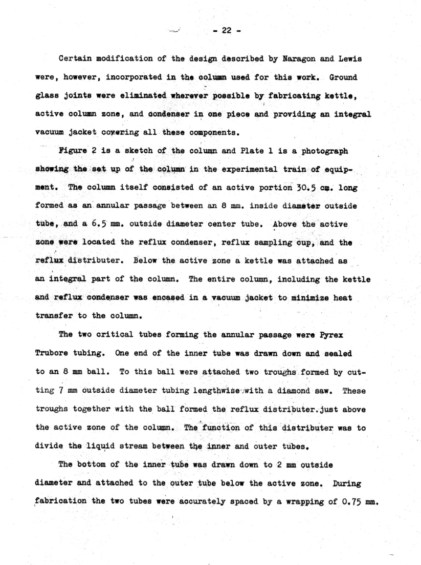
- 22
-Certain modification of the design described by Naragon and Lewis were, however, incorporated in the Column used for this work. Ground
glass joints were eliminated wherever possible by fabricating kettle, active column zone, and condenter in one piece and providing an integral vacuum jacket coyering all these components.
Figure
?
is a sketch of the column and Plate 1 is a photograph showing the set up of the column in the experimental train of equip-ment. The column itself consisted of an active portion 30.5 cIA. longformed as an annular passage between an 8 mm. inside diameter outside
tube, and a
6.5
mm. outside diameter center tube. Above the active zone were located the reflux condenser, reflux sampling cup, and the reflux distributer. Below the active zone a kettle was attached as an integral part of the column. The entire column, including the kettleand reflux condenser was encased in a vacuum jacket to minimize heat transfer to the column.
The two critical tubes forming the annular passage were Pyrex Trubore tubing. One end of the inner tube was drawn down and sealed
to an 8 mm ball. To this ball were attached two troughs formed by cut-ting 7 mm outside diameter tubing lengthwise,'with a diamond saw. These troughs together with the ball formed the reflux distributer.just above the active zone of the column The function of this distrbuter was to divide the liquid stream between tke inner and outer tubes.
The bottom of the inner tube was drawn down to 2 mm outside
diameter and attached to the outer tube below the active zone. During fabrication the two tubes were accurately spaced by a wrapping of 0.75 mm.
COOLANT IN COOLANT TO PRESS CHARGING LINE REFLUX TER LEADS CONDENSER _-REFLUX CUP -REFLUX DISTRIBUTER -SPACERS -CENTER TUBE -OUTER TUBE GLASS BELLOWS VACUUM JACKET
STILL POT SAMPLING LINE PL A TINUM HEA TER
CONCENTRIC TUBE COLUMN
FIG. 2
BURETTE
PLATE
/
CONCENTRIC TUBE COLUMN AND SAMPLING SYSTEM
-
25
-diameter copper wire on the inner tube. After fabrication and annealing,
the wire was removed by solution in sulfuric acid and potassium
dichro-mate.
The kettle was an integral part of the column and was fully vaquum
jacketed. An opening in the kettle, inclined upward at about 45 , re-ceived a standard taper 29/42 male fitting. The inner 29/42 fitting
had a central thermowell fabricated of 4 mm Pyrex tubing. Around this
tube there were symmetrically spaced three openings to receive the two
heater heads and the liquid sampling line. A seal was made between these
lines and the 29/42 fitting by 10/50 standard taper fittings.
The two heater leads passed through 7 mm. tubing attached to the
10/30 standard tapers and terminated with tungsten seals at the bottom.
The liquid sampling line was a 0.3 mm. capillary with a constriction to
0.1 mm. at the point it joins the 10/30 fitting. The lower end of the
sampling capillary was also slightly constricted and offset. The heater,
identical to that used in the equilibrium still, was fabricated as a
coil of 0.2 mm. platinum wire of 0hout 50 cm. in length. The platinum
heater was spot welded to the tungsten seals.
In addition to the vent line and the reflux sample line leaving the
upper portion of the column, another tube pierced the vacuum jacket
be-tween the active zone of the column and the condenser. This line permitted
charging the column. A 4 mm. reflux thermowell was provided just above
the reflux distributer. The reflux sampling cup held about 2 ml. of
liquid. A central funnel was provided within the cup to insure
between the inner tubes and the outside of the vacuum jacket, several glass bellows were included in the jacket for expansion. Acetone refrigerant for the condenser was provided at -70 0 C The acetone
was cooled in a coil of 1/4 inch copper tubing submerged in an
acetone-dry ice bath contained in an insulated sheet metal tank. The acetone
flowed from an expansion tank through the cooling coil, through the
column, then through a small centrifugal pump and back through a filter
to the expansion tank. (Fig. 6) All lines were insulated to conserve
dry ice and prevent excessive ice formation. Seals were made between the 1/4 inch copper tubing and the 1/4 inch glass tubing at the coluipn with "Swage-Lock" fittings with Teflon inserts.
The column was charged by injecting gaseous ammonia through the charging line at a rate of about 1.5 liters per minute. As the ammonia
was condensed and flowed down the col it cooled the column internals
and accumulated in the kettle. The colujpn was supported by 8 coil
springs to provide flexibility.
During operation the kettle was filled about half way with liquid ammonia. Care was taken to keep the level constant since separation
occuMed on the wetted walls exposed. Liquid samples could be taken at will, but a minimum of 90 minutes of continuous operation was allowed for
equilibrium to be attained before drawing reflux samples. (Sampling of the reflux was performed with the column operation halted, to prevent
contamination with material obtained under non-equilibrium conditions
All reflux samples were then representative of the total reflux operation
-
27
-the equilibrium still dictated -the necessity of providing capillary
constrictions and heated zones in the sampling lines for the co plete vaporization of the samples. Again the pressure drop through the
con-stiictions during the sampling was observed on a mercury manometer and
the heat supplied by Nichrome resistance heaters wrapped around the
7
mm. Pyrex lines and insulated with glass tape.Since all the column runs were carried out atone atmosphere, the barometer pressure readings available from the M.IT. MeteOaDogical Department were used for pressure determinations. The values reported in Table 2 were obtained by averaging the reported readings during the
interval of a run.
Temperature measurement was, as in the equilibrium still, carried
out with a Chromel-Alumel thermocouple; E.M.F. measurements being made with a Leeds and Northrup type "K" potentiometer. The errors introduced
in temperature measurement were the same ones discussed in equilibrium
still section. The important differences with the column were:
1. The kettle thermowell was overheated about 0.300. When the platinum kettle heater was operated.
2. The reflux thermowell was not reliable since it was not normally
covered with liquid reflux.
The first error was uncovered when it was observed that the indicated
temperature of the )cettle charge dropped 0.30C. immediately after shutting the heater off. The most obvious explanation is that the platinum heater
was overheating the thermowell since the contents of the kettle continued
to boil very slowly even after the heater was shut off due to heat leakage
observed when the heater of the equilibrium still was shut off, and
furthermore, the readings obtained from the column when the heater was
not operating agreed well with the still measurements. However, since
most of the temperature measurements from the column kettle were made
with the heater operating, they were 6orrected by arbitrarily
sub-tracting 0.300. This source of error was not serious since accurate
temperature measurements had already been obtained over a wide composition
range with the equilibrium still.
The reflux thermowell was not e$tuated exactly as specified in the
design of the column, and as a result the stream of reflux returning to
the column did not always pass over it. This would not have been a
serious error if the boiling point of the column contents was a4ove the
surrounding temperature, for then some condensation would have occurred
on he thermowell keeping it at the boiling point. This was not the
case with the ammonia system and whenever liquid reflux was not flowing over the reflux thermowell, the indicated temperature rose considerably
above the boiling point due to heat conduction down the thermowell. This
clearly indicates the necessity of keeping a reflux thermowell submerged
in liquid when sub-room temperatures are to be measured. Because of
this limitation, no reflux temperatures are reported in this investigation.
Unfortunately, the column did not operate reliably with the ammonia
system due to incomplete wetting of the active walls of the column.
Because the walls were not fully wetted, any change in flow regime changed
the area for mass-transfer and hence the effective number of stages obtained.
- 29
-After it was realized that wetting had become a problem several
attempts to establish uniform wetting were carried out. The column was
cleaned with hot sulfuric acid - potassium dichromate solution, followed by distilled water and pure acetone rinses. Then it was dried by a
stream of purified nitrogen passed first through a liquid nitrogen trap.
Little improvement was noted. The column was again cleaned as above,
except acetone was omitted since it was felt that it could have left a
film of grease on the walls, but uniform wetting was never obtained with
ammonia.
The effect of boil-up rate was observed from the point where reflux
just began to the flooding point. Better separation was encountered at
the low boil-up rates but results were less reproducable than at higher
rates near the flooding point despite the lower separation encountered.
This is probably due to the better wetting at this condition. The
highest number of stages obtained for the column operated on ammonia was
four at the lowest thruput, and the number decreased to 2.6 at the flooding
point.
A check was made of the column performance with the system
n-heptane-metbylcyclohexane since Naragon and Lewis
(L)
had reported up to 75 theoretical stages for a similar colun on this system. Complete wettingwas visually observed and up to 28 theoretical stages were obtained (see
Appendix Sec. B3). The reason fog the poor performance of the columpn
with this system is not completely certain, but evidently the tolerance
on dimensions and alignment of the concentric tube in this design is so
columh specifications stated by Naragon and Lewis. This result does,
however, indicate the strong effect of wetting since under similar
operating conditions only 4 theoretical stages were obtained with the
ammonia system.
Knowing that the results would be questionable, it was
neverthe-less decided to carry out a limited number of runs with the column.
These were all performed at atmospheric pressure and at the three
concentrations 0.57, 0.23, and 0.04 XFD. Since the best reproducibility
of the column stages seemed to occur near the flooding point, it was
decided to operate there during these runs. The performance of the
column was erratic, however, and no reliable measurements were obtained.
-
31
-D. Analysis for Deuterium Content
Since the difference in composition between liquid and vapor
samples in the single-stage still was in the range 0.004 to 0.010 mole
fraction deuterium, it was necessary to have an analytic method whose
precision was of the order of 0.0001 mole fraction deuterium. Many
methods of analyzing for deuterium have been developed. Due to the
different refractive indices of compounds where hydrogen has been
re-placed by deuterium, interferometry can be used to measure changes in
deuterium concentration. 'Since this method depends on the difference
in refractive index of the mediums through which light travels, it can
be used to measure the difference in composition of two samples. This
method has been used successfully by several investigators. Ingelstam
et aL (.2&) have developed an instrument for heavy water analysis that
is capable of measuring compositions within t0.0 00 0 2 mole fraction, at
all concentrations, with a sample of one ml. Gas phase interferometry
is complicated due to the long paths required for sufficient accuracy.
Using a differential method of infra-red analysis, deuterium
con-centrations in heavy water can be measured to a probable precision of
0.00003 mole fraction.in concentrations either very rich or very lean
in deuterium. Patterson (28) has developed a method using 0.5 mm.
calcium fluoride cells which yields an accuracy of
t
0.00003 molefrac-tion, but he felt that if the scattered light problem which he encountered
could be solved, an accuracy of
t
0.00001 mole fraction would not be unreasonable. Very small samples suffice.Thermal conductivity measurements of the gas phase of a hydrogen
compound would allow composition measurements to be made. However, to
get sufficient accuracy, measurements should be made on mixtures of
difference. Heumann (20) has demonstrated accuracies of t 0.0005 mole
fraction using a Gow-Mac model 60S flow type cell with hydrogen deuterium
mixtures. Small samples are sufficient for this method also.
The mass spectrometeric method makes use of the fact that atomic deuterium has approximately twice the mass of the normal hydrogen atom.
Heavy water to be analyzed is first decomposed into hydrogen and then
the hydrogen gas is bombarded by electrons to produce hydrogen ions.
These ions are then accelerated by an electric field to produce a beam
of ions. This beam of ions is dispersed into a mass spectrum by a
magnetic field, and each separate portion of the spectrum having a
dif-ferent mass is segregated by means of parallel slits. A great deal of
work has been done with this type of apparatus, and it can be used to
measure heavy water concentration to within
t
0.0001 mole fraction for samples containing about equal proportions of hydrogen and deuterium.(Q)
The elaborate equipment required, however, makes this method
prohib-itively expensive.
Among the analytic techniques which makes use of the fact that
heavy water is approximately 10 percent more dense than light water is
the standard pycnometer method. This consists essentially of determining
the weight of a known volume of water. Another familiar density
techni-que is referred to as the temperature float method. The principle upon
which the temperature float method is based is quite simple. The
temperature at which a small quartz or glass float has the same density
as an unknown water sample (i.e. the float neither rises or falls) is
compared with the temperature at which the float has the same density
as standard water. This temperature difference, together with the data
on the coefficients of expansion of water, quarts, and heavy water,
permit calculation of the density difference between the unknown and standard waters. Kirshenbaum (25) gives complete descriptions of all
these various techniques. The disadvantage of these methods is that
large amounts of water are needed.
The falling drop method for determining the density of a liquid was
first used by Barbour and Hallton (2) who utilized it in the determina-tion of the density of blood. This method, which is based on Stokes'
law, consists of allowing a small drop of liquid sample to fall through
an immiscible fluid having a density only slightly less than that of the sample. After the drop reaches terminal velocity, its rate of fall is measured by timing its passage between two scratch marks with a
stop-watch. The terminal velocity of a falling sphere is given by Stokes'
law as a function of the density difference between the two fluids.
Al-though Stokes' law is not obeyed exactly in the case of a falling liquid
drop, it does show a functional relationship between the density
dif-ference and the time of fall, therefore indidating how the density of a sample can be determined so precisely.
Keston and Rittenberg
(g)
refined the technique by carefultempera-ture control and thus were able to analyze low concentration heavy water
samples to within + 0.0002 mole fraction. Frillette and Hanle
(U)
using a mixture of alphamethylnaphthalene and phenanthrene were able to
determine within 0.0001 mole fraction the heavy water content of
These limits of concentration depend on the density of
alphamethylnaphtha-lene and the solubility of phenanthrene. The falling drop method has
been used by Bigelow,
()
who determined heavy water concentrations inthe range of 0.0001 to 0.05 mole fraction, to within
t
0.0002 to t 0.0004 mole fraction using o-fluorotoluene as the immiscible fluid. He statesthat this substance is inadequate above 0.05 mole fraction because of
the increasing difference between the sample density and the
o-fluoro-toluene density.
One distinct advantage of the falling drop method is the fact that very small samples suffice (0,1 to 005
4.).
t requires less time and less wvadar than the temperature float method. As in all density measure-ments it requires a very sensitive thermostat capable of maint&ixkng the temperature constant to within 0.00100. In spite of this fact, density methods in general all probably require less expensive apparatus thanthe interferometric, spectographic, or mais-spectrometric methods.
Density measurements, based on heavy water standards, have the disadvantage, however, that the sample of deuterated ammonia must be quantitatively
converted to water with no hydrogen contamination. This can be ac-complished by passing the ammonia over copper oxide at 70000. (16)
Due to the precision, low cost, and small samples required, the
falling drop method was adopted for the measurements of the deuterium
concentration in the wateir samples which could be obtained by quantitative
oxidation of the ammonia samples. In addition, the bath, used by
Bigelow
(§)
and set up during preliminary measurements by Kalman and-
35
-best possible fluid mixtures to cover a wide concentration range, the mixture alpha-ethylnaphthalene and methoxynaphthalene was chosen to
cover the range from 0.10 to 0.80 mole fraction deuterium. This had
the advantage over the mixture of alpha-methylnaphthalene and
phenanth-rene used in the preliminary work, in that the upper concentration that could be analyzed was 0.80 rather than 0.42 mole fraction deuterium.
For the very low deuterium concentrations the mixture
alpha-methyl-naphthalene and 1, 2, 3, 4 tetrahydlroalpha-methyl-naphthalene was chosen.
The falling drop apparatus consisted of a large constant
tempera-ture water bath which was maintained within t 0.001 0C of the set
temperature (350.). It is shown in Figv,4J3 and 4, and Plates 2 and
3.
1ithiri. the large bath was a smaller inner bath in wh ch three falling tubes were supported in a fixture which permitted spilection of one tube for a particular density. The outer bath was stirred b wo centri-fugal stirrers. The inner bath was stirred by an air bubbler. Dueto the thermal inertia of the inner bath and the falling tubes, their temperature could be maintained nearly constant. Variation of the inner bath temperature was less than 0,0020C over a 24 hour period.
The temperature of the inner bath was measured by a Beckmann Thermometer.
The falling tubes were made of 24 mm Pyrex tubing about 40 cm long4
A scratch mark was made completely around the tube about 7 cm from the bottom. A second scratch mark was made 10.00 cm. above the first, and
a third 10.00 cm. above the second. The first and third marks were
FALLING DROP ANALYSIS
F/G.
3
HEATER AND
TEMR CONTROL
OVERFLOW'
DR AIN
-37-MULTI PLE
FIXTURE
FALLING TUBES
DETAIL
OF INNER
FIG.
4
ETCHED
AIR
BATH
-,I! mom'' lm-j".w wmmmw ol Pll 11T-M- IP I IIR'Rq 11 11 F "WiRl Pi 0 1 -WWWWROR"
PLATE
2
GENERAL
VIEW
Of FALLING
DROP
APPARATUS
I ~a. I.
I