Supporting Information
Electric-field Induced Reversible Switching
of the Magnetic Easy-axis in Co/BiFeO
3on SrTiO
3Tieren Gao1, Xiaohang Zhang1,2, William Ratcliff II3, Shingo Maruyama1, Makoto Murakami1, Anbusathaiah Varatharajan4, Zahra Yamani5, Peijie Chen2, Ke Wang2, Huairuo Zhang6,2, Robert Shull2, Leonid A. Bendersky2, John Unguris7, Ramamoorthy Ramesh8, and Ichiro. Takeuchi1,*
1
Department of Materials Science and Engineering, University of Maryland, College Park, Maryland, 20742, USA
2
Material Measurement Laboratory, National Institute of Standards and Technology, Gaithersburg, Maryland 20899, USA
3
NIST Center for Neutron Research, National Institute of Standards and Technology, Gaithersburg, Maryland 20899, USA
4
Intel Corporation, Portland Technology Development, Hillsboro, Oregon 97124, USA
5
Canadian Neutron Beam Centre, National Research Council, Chalk River Laboratories, Chalk River, Ontario, Canada K0J 1J0
6
Theiss Research, La Jolla, California 92037, USA
7
Center for Nanoscale Science and Technology, National Institute of Standards and Technology, Gaithersburg, Maryland 20899, USA
8
Department of Materials Science and Engineering, University of California, Berkeley, California 94720, USA
Corresponding Author
*Email: takeuchi@umd.edu (I.T.). Tel: (+1)-301-405-6809; Fax: (+1)301-405-6327
TEM Results
Figure S1 shows the cross-sectional TEM of Pd (5 nm)/Co (5 nm)/BFO (80 nm) films on SRO layer with STO (001) substrate. It is clearly seen that the BFO film is epitaxially grown on SRO layer and the Pd and Co layer are both polycrystalline. The interface between the Co and BFO layers is sharp and clear.
Figure S1 Cross-sectional TEM image of Pd/Co/BFO layers
Neutron Diffraction
In the polarized neutron diffraction measurements, a vertically focused Heusler (He) (111) monochromator and a large flat He (111) analyzer with Ef = 13.7 meV were used. Collimations
were used to remove higher order contamination from the measurements. A five coil assembly at the sample position allowed for the neutron spin orientations perpendicular to the scattering plane Q (vertical field, VF), and parallel to Q (horizontal field, HF) and at other angles with respect to Q in the scattering plane, where Q is the position in reciprocal space. A Mezei flipper in the incident beam was used to measure both spin-flip (SF) and non-spin-flip (NSF) scattering. Non-polarized measurements in different scattering planes were performed using the E3 spectrometer at Chalk River Laboratories. A Ge (113) monochromator was used to set a wavelength of 2.37051 Å. The measurements were performed in the diffraction mode (no analyzer). Collimations were set to [none, .29°, .39°, none].
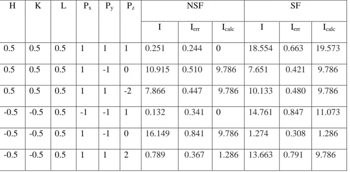
Table I: Polarized neutron diffraction measurements of two reflections compared to a model. The direction of the neutron polarization are given by Px, Py, and Pz. NSF and SF denote non spin flip and spin flip cross sections. The
integrated intensities (I) are given in arbitrary units. Error bars represent one standard deviation. Ierr and Icalc denote
intensity error and calculated intensity, respectively.
H K L Px Py Pz NSF SF
I Ierr Icalc I Ierr Icalc
0.5 0.5 0.5 1 1 1 0.251 0.244 0 18.554 0.663 19.573 0.5 0.5 0.5 1 -1 0 10.915 0.510 9.786 7.651 0.421 9.786 0.5 0.5 0.5 1 1 -2 7.866 0.447 9.786 10.133 0.480 9.786 -0.5 -0.5 0.5 -1 -1 1 0.132 0.341 0 14.761 0.847 11.073 -0.5 -0.5 0.5 1 -1 0 16.149 0.841 9.786 1.274 0.308 1.286 -0.5 -0.5 0.5 1 1 2 0.789 0.367 1.286 13.663 0.791 9.786