Publisher’s version / Version de l'éditeur: Building Practice Note, 1981-09-01
READ THESE TERMS AND CONDITIONS CAREFULLY BEFORE USING THIS WEBSITE.
https://nrc-publications.canada.ca/eng/copyright
Vous avez des questions? Nous pouvons vous aider. Pour communiquer directement avec un auteur, consultez la
première page de la revue dans laquelle son article a été publié afin de trouver ses coordonnées. Si vous n’arrivez pas à les repérer, communiquez avec nous à [email protected].
Questions? Contact the NRC Publications Archive team at
[email protected]. If you wish to email the authors directly, please see the first page of the publication for their contact information.
NRC Publications Archive
Archives des publications du CNRC
For the publisher’s version, please access the DOI link below./ Pour consulter la version de l’éditeur, utilisez le lien DOI ci-dessous.
https://doi.org/10.4224/20378198
Access and use of this website and the material on it are subject to the Terms and Conditions set forth at
Insulation retrofitting : a case history
Strelka, C. S.; Burn, K. N.
https://publications-cnrc.canada.ca/fra/droits
L’accès à ce site Web et l’utilisation de son contenu sont assujettis aux conditions présentées dans le site LISEZ CES CONDITIONS ATTENTIVEMENT AVANT D’UTILISER CE SITE WEB.
NRC Publications Record / Notice d'Archives des publications de CNRC: https://nrc-publications.canada.ca/eng/view/object/?id=189534ca-4b16-45a7-b6a6-d23bd32ebf85 https://publications-cnrc.canada.ca/fra/voir/objet/?id=189534ca-4b16-45a7-b6a6-d23bd32ebf85
Ref
ser
;
Tm.
INSULATION RETROFITTING
-
A CASE AISTOR'YC.S. StreLka and K . N . Burn
Division of B u i l d i n g Research., Eational Research C o u n c i l of Canada
INSULATION FETROFITTING
-
A CASE HISTORY byC.S. Strelka and K.N. B u m
INTRODUCTION
In the fall of 1978, the D t v i s i o n had the opportunity to
monitor a case of r e t r o f i t t i n g insulation in a two-storey balloon-frame house sttuated in an older s u b d i v i s i o n of O t t a w a . Because the house is owned by a s o c i a l service organization and m o s t of i t s rooms are used only for occasional meetings, there were no problems o f d i s t u r b i n g t h e
owners with observation activities. On the other hand, because there is a live-in caretaker, the house is kept at a comfortable temperature
at a11 times and may therefore be considered a normal residential
building with minimal occupancy effects. This house is t h e larger part of an uneven d o u b l e .
Initial i n s t a l l a t i o n of insulation above the c e i l i n g was poor, but was corrected about half-way through t h e heating season. The records therefore include the energy consumed for three different
heating conditions: without insulation; with wall insulation, but inadequate ceiling insulation; and with the ceiling insulation i n s t a l l e d as i n i t i a l l y intended.
DESCRIPTION OF HOUSE Exterior
The b u i l d i n g is a two-storey, two-unit, balloon-frame
construction w i t h a 1-mhigh vented a t t i c s p a c e beneath a f l a t roof, built sometime before t h e turn of the century. The exterior finish of
the front (street) elevation facing e a s t is cement stucco on l a t h .
At t h e second floor level on t h i s side of the house there is a s i n g l e glazed, unheated and uninsulated sun room, supported on wood columns
over the f r o n t verandah (Fig. 1). The n o r t h elevation facing a
3 m - w i d e lane has t h e same type of finish treatment (Fig. 2 ) . A t t h e
rear of the house is a one-storey addition, in which the kitchen is
located ( F i g . 3 ) - The exterior f i n i s h of the rear (west) elevation i n c l u d i n g the kitchen a d d i t i o n is a l s o stucco on lath. The unheated
rear entrance porch has aluminum c l a d d i n g . The south wall of the observed p a r t of the b u i l d i n g is not exposed to the external environ-
ment. It forms a party w a l l between the two housing u n i t s and i s constructed of wood frame with board sheathing and plaster lath on
for all exterior walls (Fig. 4). The roof of the buflding is flat, w i t h minimum slope towards the inside roof drain. An attic space is
formed by a frame structure extending about 1 m above the second floor c e i l i n g . There is no p h y s i c a l separation between the t w o u n i t s
in t h i s space.
Interior
The sketch floor plans of t h e observed part of the building with use of i n d i v i d u a l rooms indicated are shown in F i g s . 5 and 6 .
Interior finish on all exterior w a l l s and partitions is p l a s t e r over
wood lath over 13-mm boards. Windows
All windows i n t h e b u i l d i n g are wood-frame single-glazed vertical sliders with allrminum frame single-glazed vertical slider
storm windows attached to the exterior face of the wooden window frame. Basement
Basement w a l l s are constructed of stone masonry approximately
300 rmn t h i c k unfinished on t h e i n s i d e face. The retrofittfng program d i d not include adding insulation to the basement walls.
Heating System
An o i l - f i r e d furnace (Beach L0137, Output 40 150 W) w i t h forced warm air heating system is situated in the basement.
INSULATION RETROFITTING
As already mentioned, both u n i t s of the double-house structure were retrofitted at the same time. The contractor recommended providing
a polyethylene vapour barrier over the floor in the attic space including
the separate a t t i c over t h e kitchen addition and then blowing in loose
cellulose f i b r e insulation t o the thickness of approximately 200 mm over
the full area of the vented a t t i c space. The proposed i n s u l a t i n g value
w a s RSI 6.2. Calculations by t h e authors, based on the volume of
insulatfon the c l i e n t was b i l l e d for, indicate that the resulting value
after retrofitting should have been RSI 5.1.
The same type of insulation m a t e r i a l was used for t h e exterior walls.
In balloon-frame construction the f l o o r joists are supported
on ledger boards on t h e inner face of t h e studs rather than on plates as w i t h p l a t f o r m construction. T h i s makes access to the wall cavities
from above relatively simple. The method followed therefore w a s to fill between the studs from t h e a t t i c space by blowing in loose insulation. The wall cavities below the windaws w e r e f i l l e d using
h o l e s of approximately 25 mm d r i l l e d vertically through the window afXls, The insulation value of the exterior w a l l s was estimated by the
contractor as RSI 2.8; calculations confirm this estimate. Retrofitting w a s cuarple~ed by 20 October 1978.
According to t h e invoice submitted by the contractor to the
owners, 46 bags of insulation (0.33 m3 per bag) were used to insulate the at tic space,
and 42
bags w e r e b l m 5nto the w a l l cavf ties. Thequantity of mater3al used in t h e insulated areas was calculated as
follows : A t t i c S n a c e s
House
...
7.300 x 7,300 m = 53.29 TI?Kitchen
...
5.200 m x 4.400 m = 22.88 m2After 10% reduction for j o i s t s , eec,
...
= 68.55d
Assuming insulation thickness equalto j o i s t depth
.
i.
e..
200 m, volume...
= 13.7d
3
Insulation used
...
46 bags a£ 0.33 m each...
= 15.2 m3Exterior Walls
A f t e r deduction for door and window openings
...
139 m2Waf1 cavity
...
100 mm..
Available cavity volume (20% reduction for framing). 11.1 m3 3
Insulation used
-
42 bags of 0.33 m each...
13.9 m 3 The total cast of labour and material s u p p l i e d was $1350. INSPECTION OF COMPLETED RETROFITTINGIn February
1979
a partial thermographic survey of the retrofitted b u i l d i n g w a s conducted both outside and i n s i d e using an AGA 680 thermovZsion camera. The insulated building envelope wasf i r s t scanned and then p i c t u r e s were taken at various p o i n t s where
the infrared images showed temperature patterns indicating heat losses
greater than normal. At t h e time of this survey, the temperature inside the house w a s 2 4 O ~ . A similar procedure was a p p l i e d to
i n s p e c t i o n on t h e exterior of t h e b u i l d i n g , bur because the o u t s i d e temperature was -15'~~
which
was cold enough to freaec t h e cameraequipment: after approximately half an hour of work, only three pictures
were taken.
The following is a list of representative themgrams taken during t h i s survey together with interpretations of the t h e m 1
conditions they d e p i c t . The areas in rhe themgrams appear as shades of grey varying in Tntensfty f r o m black t o w h i t e illustrating relative surface temperature for t h e same surface material. The coldest areas
are black and the warmest are whlte. When viewed from t h e i n s i d e a well-insulated section crf
wall
appears vamer than one t h a t is not,because the insulation reduces the rate of heat loss from the inside
sursace to the outside. When viewed from the o u t s i d e a well-insulated section of a wall appears colder than one that is not,because Ehe
insulation retards t h e conduction of heat from the i n s l d e to the
outside surface. The thenmgrm numbers and locations are shown on the floor plans in Figs
-
5 and 6 .F i g .
F i g .
F i g .
7: The front elevation of the building showing heat loss through windows, through t h e uninsdated upper part of t h e exterior wall at attic l e v e l , by a i r leakage ar thermal bridges formed by the wood structure and hy air leakage from t h e rminsulated sun room over t h e verandah;
8: The cold p a r t of a wall of t h e meeting r o o m on the f i r s t flanr indicating t h a t insulation is missing;
9 : The corner at the exterior w a l l between the meeting room and the pantry indicating i n s u f f i c i e n t or missing
insulation;
F i g . 10: The c o l d corner in t h e upstairs mail room;
F i g . 11: An exterior shot of the s a m e corner;
F i g . 12: The diagonal line at t h e bottom edge of a dark area indicating a structural membe~ which obstructed t h e downward movement of insulation, resulting in an uninsulated cavity below. This thermograrn a l s o shows
poor insulation ah t h e southwest corner of t h e building. Fig. 13: The ceiling in the second floor -bathroom showing
uninsulated joist spaces adjacent to the exterior wall;
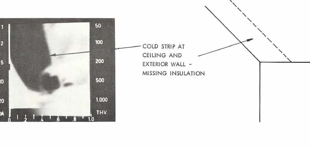
F i g . 14: The ceiling and wall at the outside corner of t h e second floor bedroom showing insufficient insulatlton.
After the thermographic survey and the i n i t i a l evaluation of the thermograms, a physical inspection 0 5 insulation was conducted. As no destructive probing of the exterior w a l l s was permitted, t h i s w a s restricted t o visual inspection of the a t t i c space only. The
Tnspection confirmed t h e thermographic f i n d i n g s . Uneven diszribution of insulation and empty j o i s t spaces especially at the edges and
comers of the roof were caused
by
an hproper installation techniquewhen the applicator, for lack of space or for h i s convenience, stood
in the open c e i l i n g hatch and f r o m t h i s paint d i r e c t e d the nozzle all around. This resulted in the i n s u l a t f ~ n being stopped by the c e i l i n g j o i s t s perpendicular to the directiun of f l a w . Insulation was thus heaped m one s i d e of most c e i l i n g frame members, but behind t h e j o i s t s ,
t t
on the lee" side, the thickness of l n s u l a t f w was minimal. Close to t h e hatch the spaces were adequately f i l l e d ; in p l a c e s f u r t h e s t from the hatch around t h e perimeter of the c e i l i n g , insulation was t o t a l l y
missing or was minimal in d e p t h (Figs. 15 to 17). This situation was
pointed out to the contrator, who remedied it by adding 26 bags of insulation and raking it t o an even lager over t h e entire floor in the
a t t i c space to the thickness of approximately 200 mm. C e i l i n g Insulation Thickness Before and After Inspection
Theoretically, 15.2 m3 of insulation used in the first stage
in the a t t i c should have covered the entire floor area to the d e p t h
of
200
mn (15.2d
+76.17
II? = 200 m). Reduction in insulated area,caused, e . g . , by j o i s t s , should have resulted in an even greater thickness of insulation. According to Bomberg a d S h i r t l i f f e (19781, a layer of
blown cellulose f i b r e . insulation on £1 at surfaces is subj ecred to approximately 20X s e t t l i n g during and after installat-ion.
If
p r o p e r l y i n s t a l l e d , the Insulation layer in the a t t i c should s t i l l have been 175 mm thick. Smallerthan
expected savings on heating energy achieved during t h e heating season after i n i t i a l retrofitting and visualinspection of the a t a c confirmed that the proposed thickness was not
i n s t a l l e d . The required thickness of insulation and expected savings
on
energy were reached only after the a d d i t i o n a l 26 bags of insulation were added and placed properly, i,e,, ta t h e top o f the j o i s t s . The26 bags of insulation produced a n addittonal thickness of 100 mm
over the whole attic area.
These calculations and t h e i n s p e c t i o n suggest three possible
c~lclusions:
a) the 5nsulation material settles much more than 20% after befng
b l m in;
b) because two housing u n i t s were r e t r o f i t t e d at the same time, more material w a s used for t h e other u n i t than estimated by
or c) t h e recorded quantity of insulation w a s not a p p l i e d , e s p e c i a l l y
to the a t t i c area.
There are strong indications that the last-mentioned w a s the case,
COMPARISON OF FUEL USAGE BEFORE AND AFTER REXROFI7TING
Table I shows the fuel consumption during t h e heating season: (1) before Znsulatfon retrofitting
(2) for 4 112 months when the insulation in the attic was not
properly i n s t a l l e d
,
and( 3 ) after the remedial action w a s taken. Table 1 Aetual F u e l Consumption
As fndlcated in Table I the winter periods of 1978-79 and
1979-80 w e r e 4.5% and 9.5X milder than the winter of 1977-78, on the b a s i s of degree-days. Heating Period (1) O c t . 77
-
Apr. 78 (2) O c t . 78-
Apr. 7 9 (3) Oct. 79-
Apr. 80To provide the proper camparism of f u e l consumptfon and to indicate t h e actuel energy savings, t h e fuel consumptim for the
h e a t i n g seasons of 1978-79 and 1979-80 w a s recalculated so that the numbers of degree-days were the same as for the heating p e r i o d of 1977-78. This adjustment is shown in Table 11;
Where: Fuel Consumption, L 8215 6816 5394
A
...
Actual fuel consumption for heating season 1977-78;A~
...
Actual fuel consumption fox each heating season;AC
-.
Carrected f u e l consumptioa for heating season calculated;Z
of (1) 100 83.0 65.6 Degree- Days, (DD) 1 8 0 ~ 4416 4219 3996 % o f DD 100 95.5 90.5DD
...
Z
differencein
degree days between heating season 1977-78and heating season caliculated;
S
...
Puel savings for years of equal number of degree days. Table I1 Adjusted Fuel Conswnptlon and SavingsMonitoring t h e retrofitting operatfan of t h i s house has shown that even w i t h the b e s t intentions and techniques, the results
of insulating in restricted spaces and closed wall cavities are not always, and probably cannot be, c o q l e t e l y e f f e c t i v e . The job m i g h t
not be completed as intended, unless the contractor suggests, a r the owner requires and is prepared to accept the additional c a s t of,
themnographic inspection after the retrofitting and is prepared to a c t
upon its f i n d i n g s .
Heating f eriod
1977-78 1978-79 1979-80
An example drawn from t h i s case m a y be illustrated using
Fig. 12. The thermogram shows a diagonal framing member in the
exterior w a l l which prevented proper fllling of the wall cavity with insulation. The contractor, after h i s i n i t i a l Inspection, assumed t h i s house to be a two-storey ballam-frame structure. But he could not
have khown that some time in the past a secand storey had been added, The diagonal member in question could have been a part of the o r l g f n d
roof franie or bracing l e f t in t h e wall,
+ DD
,
3 ,X
L 8215 100.0-
- 6816 95.5 713 7 f 078 5394 90.5 5960 2255Again, inspection of t h e attic space after retrofitting confirms h m important it is for the owner to require the contractor
to dlemcmstrate that the work has been done properly. As shown in t h e
S column in T a b l e If, correction of the situation which included
adding insulation and raking it to an even layer resulted in doubling
the s a d n g s .
CONCLUSIONS
The monitoring of this particular retrofittling operation
demonstrates clearly how, by addjng i n s u l a t l m in exterior walls and
conservation
of
energy and ffnancial savings can be achieved. In practice, the costof
r e t r o f i t t i n gwill
probably be recovered in ashort time.
The
following basic figures apply in t h i s case: Initial costof
~etrofitting: $1350.09Heating o i l price:
1st heating season after r e t r o f i t t i n g C13.9/L 2nd heating season after r e t r o f i t t i n g C15,7/L
3 r d heating season after retrofitting (Jan 811 C21.81L Assuming
tha-t:
energy savings over the folfowing years will average 2255 L/year and that the price of h e a t i n g 011 w i l lincrease by 20% per year, dollars saved over four heating seasons will be:
Heating Season Amount of Fuel
Used,
L times times times times Priceof
$ O i l / L Savedc
13.3 = $149.84 15.7 = 354.03 21.8 = 491.59The i n i t i a l c o s t of retrofitting to the owner will therefore be recovered in approximately four heating seasons, after which the reduction in annual energy costs represents considerable savings.
This
calculation, however, omits the effect of i n t e r e s t that: would accrue to the owner had he invested h i s money in some other way, nor have the various subsidies available tohomeowners
f o r insulatiohr e t r o f i t t i n g been considered. ACKNOWLEDGEMENTS
The authors express appreciation to t h e i r colleagues
G.D. Schuyler
and
J.A.~ichardson
for their assistance inthis
s t u d y and in particular for obtaining the thermograms which constitute an important part of the post retrofit inspection.Reference
1 Bomberg,
M.
and C. J, Shf r t l i f f e . Blom c e l l u l o s ~ f i b e r thermali n s u ~ a t f o n s , Part
1
-
Density of c e l l u l o s e f i b e r thermal insulatian in horizontal applications. ASTM Special Tech.Pub. 660, p . 82-103. Dec. 1978- BIBLIOGRAPHY
Bomberg, M. and C . J . Shirtliffe. Comments on standardization of density and thermal resistance testing of cellulose f i b r e Fnsufarion for horizontal applications, NRCIDBR, B u i l d i n g Research Note 147,
May 1979.
Bomberg, M, and K-R, Solvason. How t o ensure good thermal performance
of cellulase f i b r e tnsufntion: P a r t I
-
Horizontal applications.NRC/DBP, Building Research Mate 157, March 1980; Part 2
-
Exter-lor w a l l s . NRCIDBR, Building Research Note 158, March 1980. B d e r g , M. and K.R. Solvason. HOW to ensure good thermal performance of
blown mineral fibre insulation in horizontal and vertical
installations. MRC/DBH, Building Research Note 167. August 1980. Burn, K.N. and G,D. Schuyler. Applications of infrared thermography in
locating and i d m t i f y 3 n g building faults. ;Tour. Internat. I n s t .
f o r Consenration
-
Canadian Group, V o l . 4, No. 2, p. 3-14,Spring 1979.
S h i r t l i f f e , C.J, and H. Bumberg. Blown c e l l u l o s e fiber thermal insulations, Part 2
-
Thermal resistance. ASTM Special Tech, Pub. 660,7
U n i n s u l a t e d F i g . 2. s i d e V i e w F i g . 1 . F r o n t V i e w U n i n s u l a t e d Rear E h t r a n c e Porch F i g . 3 . R-ear V i e w*I7
mm C e m e n t S t u c c o on Wood L a t h 1 3 mm Board S h e a t h i n g 1 0 0 mm S t u d S p a c e Filled w 1 t h L o o s e Cellulose F i b r e l n s u l a t l o n 1 3 mm Board I n t . S h e a t h i n g1 3
rnm P l a s t e r o n P l a s t e r L a t h F I G U R E 4 T Y P I C A L E X T E R I O R W A L LMot Hon l t a r e d Note : D l mensl ons a re i n mftlfrnctres F I G U R E 5 G R O U N D F L O O R P L A N
Hot Mnn I tored
Sun P o r c h
(Un insulated)
F I G U R E 6
1.000 I THV
n
F I G U R E8
,PICTURE
ON
WALL
-
MlSSlNG INSULATION
BETWEEN WINDOW
A N DCORNER
OF
THE ROOMFIGURE
13
BATHROOM
C E I L I N G
A N D THERMOGRAM
COLDSTRIP
AT
CEILING
A N D
EXTERIOR
WALL
-
MISSING JNSULATI
COLD STRlP
AT
L
CEILING
A N D
EXTER1 OR COR'NER
FIGURE 1 4
F I G U R E 15
A T T I C
SPACE I N S U L A T I O N B E F O R E R E C T I F I C A T I O N- -
C L O S ETO
H A T C H F I G U R E 16A T T I C
SPACE I N S U L A T I O N B E F O R E R E C T I F I C A T I O N- -
A TE X T E R I O R
W A L L- -
S E E F I G .14-
T H E R M O G R A M A T ~ C I I ~ I P I O ~ A \ A I ID i r e c t i o n o f A i r F l o w