HAL Id: hal-01420925
https://hal.sorbonne-universite.fr/hal-01420925
Submitted on 21 Dec 2016HAL is a multi-disciplinary open access archive for the deposit and dissemination of sci-entific research documents, whether they are pub-lished or not. The documents may come from teaching and research institutions in France or abroad, or from public or private research centers.
L’archive ouverte pluridisciplinaire HAL, est destinée au dépôt et à la diffusion de documents scientifiques de niveau recherche, publiés ou non, émanant des établissements d’enseignement et de recherche français ou étrangers, des laboratoires publics ou privés.
Modified coin cells to evaluate the electrochemical
properties of solid-state fluoride-ion batteries at 150°C
Antonin Grenier, Ana Gabriela Porras Gutierrez, Henri Groult, Damien
Dambournet
To cite this version:
Antonin Grenier, Ana Gabriela Porras Gutierrez, Henri Groult, Damien Dambournet. Modified coin cells to evaluate the electrochemical properties of solid-state fluoride-ion batteries at 150°C. Journal of Fluorine Chemistry, Elsevier, 2016, 191, pp.23 - 28. �10.1016/j.jfluchem.2016.09.006�. �hal-01420925�
1
Modified coin cells to evaluate the electrochemical properties of
solid-state fluoride-ion batteries at 150 °C
Antonin Grenier a, Ana Gabriela (first name) Porras Gutierrez (last name) a, Henri Groult a,
Damien Dambournet a,*
a Sorbonne Universités, UPMC Univ Paris 06, CNRS, UMR 8234, PHENIX, F-75005 Paris, France
* Corresponding author.
Adress : Laboratoire PHENIX, UMR 8234, Université Pierre et Marie Curie, 4 Place Jussieu, 75005 Paris, France.
Tel. : +33144273194
E-mail : damien.dambournet@upmc.fr
Abstract
In the scope of developing new chemistries for electrochemical energy systems, rechargeable solid-state fluoride-ion batteries are attractive devices owing to their high theoretical energy density. State of the art of fluoride ion conductors require the use of high temperature electrochemical cells to overcome the low ionic conductivity of the electrolyte at room temperature. In this work, we modify a coin cell to evaluate the electrochemical properties of fluoride-ion batteries at elevated temperature, over long periods of time and outside a glovebox. The coin cell is covered by a high-temperature epoxy resin that enables efficient sealing and therefore protection against air atmosphere at 150 °C. The suitability of the setup is confirmed by electrochemical investigation performed on a symmetrical cell assembled with composite electrodes made of Bi and BiF3. Notably, a reversible capacity of around 190 mAh/g after 3
2 Keywords
Electrode; metal fluoride; conversion reaction; fluoride shuttle; reversible capacity; hermetical sealing
1. Introduction
Owing to the high electronegativity of fluorine, the electrochemical reaction of a metal M with fluoride ions F- to form a metal fluoride MFx can lead to a large change in Gibbs free energy,
inducing high theoretical electromotive forces (emf) in electrochemical cells. Although the study of systems relying on fluoride shuttle started in the mid 70’s[1–5], Anji Reddy and Fichtner were recently the first to valid the concept and the feasibility of a rechargeable Fluoride-Ion Battery (FIB)[6]. Upon discharge, the MFx cathode is reduced down to its metallic
state M, while the metal anode M’ is simultaneously oxidized to give M’Fx, according to the
following reactions:
At the cathode: 𝑀𝐹𝑥 + 𝑥𝑒− → 𝑀 + 𝑥𝐹− 1.
At the anode: 𝑀′ + 𝑥𝐹− → 𝑀′𝐹𝑥+ 𝑥𝑒− 2.
Overall: 𝑀′ + 𝑀𝐹𝑥 → 𝑀′𝐹𝑥 + 𝑀 3.
These reactions, which may be classified as conversion reactions, are multi-electronic processes. Associated with large emf, some combinations of fluorides could deliver theoretical energy densities as high as 5000 Wh.L-1[7], values much larger than those obtained with
conventional lithium-ion batteries.
However, considering the relatively poor conductivity of solid fluoride electrolytes[8–13], it is required to evaluate solid-state FIBs at higher temperatures, typically 150 °C. Indeed,
3 performing electrochemical testing at 150 °C decreases the cell internal resistance and enables the use of higher current densities (10 µA/cm² [7,14]). These current densities are in the order of magnitude of those typically employed in solid state lithium batteries operating at room temperature (≥ 64 µA/cm² [15–20]).
Typical battery testing systems rely on coin cells or Swagelok type cells. Coin cells generally use polyethylene (PE) or polypropylene (PP) sealing O-rings that soften and age quickly at high temperatures, leading to the loss of sealing properties of the cell, and therefore, to the oxidation of the battery materials. Similar observations can be made with Swagelok type cells. The sealing of Swagelok type cells is generally ensured by polytetrafluoroethylene (PTFE) rings. While PTFE presents a higher fusion temperature than PE or PP, it is also subject to softening and to significant creeping at elevated temperature, due to its glass transition temperature of 115 °C. The creeping of PTFE eventually leads to a loss of the sealing properties of the Swagelok type cell. Early experiments carried out with a conventional Swagelok type cell placed in an oven at 150 °C confirmed that the sealing properties were lost after a few days. Moreover, the PTFE sealing rings were permanently damaged as they were significantly deformed. Other commercial systems are available, but they all rely on polymeric seals which are not adapted for high temperature operation. The development of a high-temperature (300 °C) Swagelok type cell has already been reported elsewhere[21], but its development requires significant modifications and machining work.
Here, we report a simple and rapid method to prepare modified coin cells particularly adapted to the study of FIBs at 150 °C, over long periods of time.
4
2. Results and discussion
2.1. Cell modification
CR2032 coin cells (MTI Corp) were chosen as the starting setup. In order to obtain a coin cell featuring high temperature resistance, the cell was covered with an epoxy resin (Loctite EA 9492) selected for its room temperature curing and high temperature resistance properties over long periods of time (i.e. no degradation of the strength retention after 3000 h at 150 °C, according to specifications). The use of an epoxy resin on the surface of the coin cell constitutes a simple and rapid approach to obtain electrochemical cells that can achieve high-temperature (150 °C) hermetical sealing.
A schematic representation of the modified CR2032 coin-cell is presented on Figure 1. All parts are made from 304 stainless steel. The case sealing O-ring is made of PP, and is already mounted on the negative side of the case. Some modifications are necessary to adapt the CR2032 coin cell dimensions (⌀int 16.4 mm, 2.8 mm thickness when crimped empty) to the FIB’s dimensions assembled for this study (⌀int 10 mm). A flat PTFE washer is used to maintain the FIB at the center of the coin-cell, and a flat wave spring (⌀14.4 mm, 1.5 mm thickness when fully expanded) and spacers (⌀15.4 mm, 0.5 mm thickness) are used to ensure electrical contact and to adjust the thickness of the FIB to the internal space available in the coin cell.
5
Figure 1. Schematic representation of the cross-section of the modified coin-cell placed on the test bench.
After assembling and crimping the coin cell within the glove box, the epoxy resin is deposited under air atmosphere.A steel pellet, used as a support and for electrical contact, is attached to the negative side of the coin-cell case with silver paint. Both the coin-cell and the contact steel pellet are thoroughly degreased with acetone prior to resin application. Additionally, the positive side of the cell is masked with tape to avoid resin covering. The modified coin-cells obtained after curing (24 h) of the epoxy resin (Figure 2.a) are placed on the custom made electrochemical test bench (Figure 2.b) placed in an oven, heated to 150 °C for electrochemical evaluation.
6
Figure 2. Photograph of (a) the modified coin-cells and (b) the electrochemical test bench placed in an oven.
The coin cells are tightened between a contact rod (bottom) and a screw (top) and connected to a potentiostat. The pressure screw maintains the modified coin-cell in place and keeps a constant pressure on the FIB placed within the coin-cell to maintain electrical contact.
To confirm the proper sealing provided by the epoxy resin, electrochemical testing is performed on pristine coin cells and coin cells covered by epoxy resin.
2.2. Electrochemical testing
A symmetrical cell relying on the Bi3+/Bi redox couple was selected to confirm the sealing since
its reversibility was demonstrated by Anji Reddy and Fichtner[6]. The electrolyte selected for our electrochemical investigation is Ba-doped LaF3. Ball-milling LaF3 and BaF2 is an easy
7 structure (trigonal, P-3c1) which offer a fluoride-ion conductivity of about 10-5 S·cm-1 at 150
°C[9,22]. For our study, La0.95Ba0.05F2.95 (denoted LBF hereafter) was used.
LBF (60 wt %) and carbon black (C, 10 wt %) were hand-milled with Bi and BiF3 (15 and 15
wt %) to produce the Bi-BiF3-LBF-C composite electrode. Two Bi-BiF3-LBF-C|LBF|Bi-BiF3
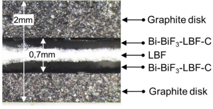
-LBF-C stacks were pressed between two graphite disks, acting as current collectors, to form a pellet. A cross section of the stack obtained is shown on Figure 3.
Figure 3. Optical micrograph of the cross section of the graphite|Bi-BiF3-LBF-C|LBF|Bi-BiF3-LBF-C|graphite stack.
The stacks obtained were placed in a coin cell as described above. One coin cell was covered with epoxy resin and the other was not. The two cells were placed on the electrochemical test bench at 150 °C and cycled between 1 and -1 V at 4.5 µA/cm² for 3 cycles (Figure 4.)
8
Figure 4. Charge-discharge curves obtained for the Bi-BiF3-LBF-C|LBF|Bi-BiF3-LBF-C symmetrical cells with epoxy resin sealing (top) or without (bottom). The cells were cycled with a current of 4.5 µA/cm² between +1 V and -1 V. The numbers indicate the order in which
each charge/discharge was recorded.
Both cells show similar behavior in the first cycle with a charge capacity lower than the discharge capacity, which can be explained by the fact that the BiF3:Bi ratio (1:1 initially) is
modified after the 1st charge, creating an excess of Bi at the cathode and BiF
3 at the anode. The
Bi and BiF3 converted during the 1st charge can then react during the 1st discharge giving rise
to a larger capacity compared to the 1st charge step.
The specific capacity observed during the 1st charge is largely inferior to the theoretical capacity
9 explained by the presence of isolated particles of active material (i.e. Bi and/or BiF3 not in
contact with LBF and carbon), which cannot contribute to the electrochemical reactions. It is anticipated that an optimization of the electrode composition, associated with a more thorough mixing (e.g. ball-milling), would lead to higher capacities in the 1st charge.
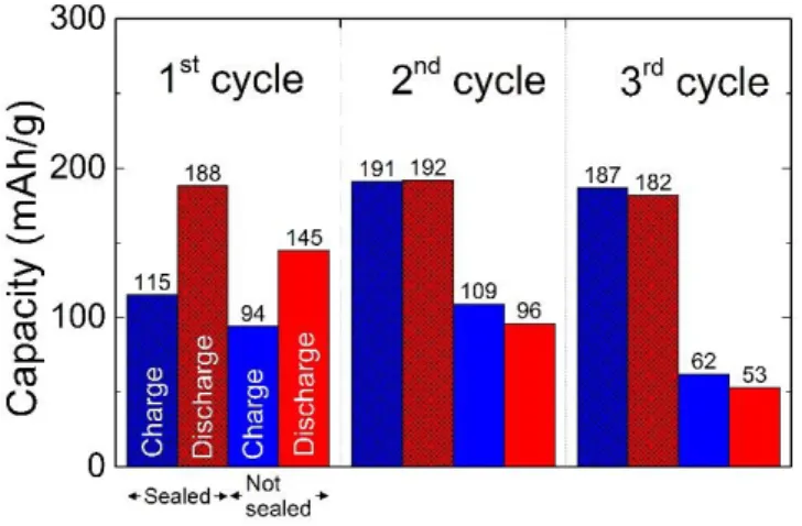
The capacities obtained for both cells upon cycling are reported on Figure 5. Charge and discharge capacities remain almost similar for the sealed cell, while the cell not sealed with resin shows a progressive loss of capacity upon subsequent charge or discharge.
Figure 5. Comparative of the cycling behavior of the two Bi-BiF3 symmetrical cells with or without epoxy resin.
The discharge capacity of the sealed cell remains stable at around 190 mAh/g for the first two cycles and slightly fades in the 3rd cycle (182 mAh/g).
For the non-sealed cell, the discharge capacity quickly fades from 145, to 96, to 53 mAh/g from the 1st, to the 2nd, and 3rd cycle, respectively. The capacity fading observed in the non-sealed
cell is significantly higher than in the coin-cell covered with epoxy resin.
Capacity fading is a typical phenomenon observed in conversion electrodes for lithium-ion batteries.[23–25] It is generally attributable to the volumetric variations of the active material upon cycling (lithium input and output), leading to a partial loss of contact with the conductive
10 additive, creating isolated particles of active materials which cannot contribute to the electrochemical reactions. Similar considerations can be made for FIBs. Reduction of BiF3
(Orthorhombic, Pnma space group) to Bi (trigonal, R-3mH space group) leads to a volumetric variation of -57 %, and oxidation of Bi to BiF3 leads to a volumetric variation of +36 %. For
the sealed cell, the slight capacity fading observed after 3 cycles may be explained by these volumetric variations. As for the increase of capacity between the 1st and 2nd discharge, a
reorganization of the electrode structure may be responsible. The low melting point of Bi (271 °C) may be responsible for the grain growth of the Bi phase[7]. While this phenomenon could be detrimental to the capacity due loss of reactive interfaces, it could also be beneficial depending on the starting microstructure of the composite. Indeed, previously isolated Bi particles may merge with other reactive Bi particles, increasing the net amount of Bi available for electrochemical reaction.
As for the non-sealed cell, the larger decrease of capacity upon cycling may be explained by a loss of the sealing properties of the coin-cell after prolonged air exposure at 150 °C (55 h at the end of the 1st charge, more than 2 weeks at the end of the 3rd discharge). Slow diffusion of air
within the coin-cell would lead to a progressive oxidation of the Bi particles upon cycling. The passivated Bi particles would be therefore rendered electrochemically inactive, inducing a progressive loss of capacity upon cycling.
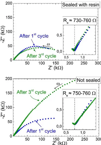
Figure 6 shows the Nyquist plot of impedance spectra recorded for the two cells, after the 1st
and the 3rd charge-discharge cycles. The spectra are all composed of a single visible semi-circle.
The low frequency zone of the Nyquist plots (Figure 6, insets) shows the end of another contribution which is attributed to the ionic resistance of LBF layer. It is expected that the electrolyte layer yields a semi-circle at high frequencies, but the frequency used here is too low
11 (i.e. 300 kHz) for the entire semi-circle to be visible. A value of approximately Re = 750 Ω for
both cells is found, which is concomitant with the resistance given by a layer of LBF in our experimental conditions (σi(150 °C) ≈ 9.4×10⁻⁵ S.cm-1 for La0.95Ba0.05F2.95)[9].
The visible semi-circle is linked to electrode phenomena, such as charge transfer resistance. In the case of the sealed coin-cell, the resistance remains relatively similar between the 1st and 3rd
cycles. For the coin-cell not sealed with resin, the resistance dramatically increases between the 1st and 3rd cycles.
Figure 6. Nyquist plots of the impedance spectra recorded on the Bi-BiF3 -LBF-C|LBF|Bi-BiF3-LBF-C cells with epoxy resin sealing (left) or without (right) after the 1st and 3rd cycles.
Insets: zoom in on the low frequency regions showing the end of the 1st semi-circle corresponding to the resistance of the LBF layer. Re denotes the resistance of the electrolyte.
12 The impedance measurements support the cycling performance observed for the two cells. Indeed, the relatively stable electrodes’ resistance yielded by the sealed cell between the 1st and
3rd cycles supports the capacity retention observed upon cycling.
In the case of the coin cell not sealed with epoxy resin, impedance measurements support the large capacity fading observed. Indeed, the loss of sealing properties of the coin-cell upon prolonged air exposure at 150 °C leading to a passivation of Bi within the composite electrode would lead to an increased resistance of the electrodes.
Figure 7 shows photographs on the cells before and after the cycling experiments carried out at 150 °C. The total length of the experiment was approximately 1 month.
After such exposure, the outside surface of the epoxy resin is browned due to oxidation. The resin was broken down to check the coin cell O-ring. The resin in contact with the coin-cell was not browned like on the outside surface and adhered relatively well with the metal surface of the coin-cell case. The PP O-ring of the coin cell protected with resin was swollen but did not present any cracks or any sign of significant aging.
13
Figure 7. Photographs of coin-cells before and after exposure at 150 °C for about 1 month, without or with the use of epoxy resin. The browned resin was broken down to let the O-ring
visible.
However, the O-ring of the coin-cell not protected with resin was significantly aged and presented multiple cracks. The aged O-ring was brittle and could be easily broken down. The observations made on the coin-cells suggest that the epoxy resin protected the PP O-ring from significant degradation, which allowed the cell to remain hermetical.
For the non-covered cell, the brittle nature and cracks present on the O-ring suggest that the sealing of the coin-cell was not achieved anymore, which must have allowed air to diffuse within the coin-cell.
These observations are in agreement with the electrochemical results obtained on the corresponding cells. Indeed, the diffusion of air within the non-sealed coin-cell may be responsible for the progressive oxidation of the Bi-BiF3 composite, eventually leading to a
passivation of the Bi particles, rendering them electrochemically inactive. The passivation of the Bi particles would explain the increase of the impedance of the cell as well as the progressive
14 decrease of the capacity upon cycling. Covering the coin cell with a high temperature epoxy resin provides protection of the O-ring, preventing air to diffuse within the cell and allowing to maintain the inert atmosphere throughout the electrochemical investigation.
3. Conclusions
Electrochemical investigations performed at 150 °C on a symmetrical cell assembled using composite electrodes composed of a mixture of Bi, BiF3, electrolyte (La0.95Ba0.05F2.95) and
carbon black, show that an epoxy-sealed coin cell can be cycled with little capacity fading (about 190 mAh/g of Bi after 3 cycles), while a non-sealed cell shows significant capacity loss (about 60 mAh/g of Bi after 3 cycles). The cycling results are in agreement with the significant increase of the internal resistance of the non-sealed cell, as observed by impedance spectroscopy. Post mortem observations of the coin cells after experiment corroborate the electrochemical results as the epoxy sealed coin cell O-ring shows no sign of significant degradation, while the non-sealed coin cell O-ring was burnt.
The covering of a coin cell with a high temperature epoxy resin is particularly adapted to study cells based on fluoride shuttle as it enables electrochemical investigation under inert atmosphere, outside a glovebox, at 150 °C and over long periods of time. Moreover, the setup described allows to maintain the cell under constant pressure, which may be beneficial to the electrochemical performance of such system.
4. Experimental
Unless specified otherwise, all the manipulation of the materials and assembly of the cells were carried out in a dry Ar glove box (H2O < 2 ppm).
15 4.1. Materials preparation
La0.95Ba0.05F2.95 (LBF) electrolyte was prepared by direct mechanosynthesis from commercial
fluorides LaF3 (Alfa Aesar, 99.99 % anhydrous REO) and BaF2 (Strem 99.99 +% Puratrem) in
purified N2 atmosphere. A Fritsch pulverisette 7 premium line planetary mill with ZrO2 jars and
milling balls (10 balls, 10 mm diameter) was used. To produce 4 g of LBF, the mixture was ball-milled for 12 hours at 400 rpm. A comprehensive study of the influence of the mechanosynthesis parameters on the structural and conduction properties of LBF can be found in the paper of Chable et al.[22]
To prepare the Bi-BiF3-LBF-C composite electrode, β-BiF3 (Alfa Aesar, 99.999%) and Bi (Alfa
Aesar, -200 mesh, 99.999%) commercial powders were mixed with LBF and carbon black (Pure Black, Superior Graphite) in 15:15:60:10 % wt ratio. The mixture was hand-milled for about 30 minutes in a dry Ar glove box with an agate mortar and pestle.
4.2. Cell assembly
Symmetrical cells were assembled, in a dry Ar glove box, using approximately 16 mg of the Bi-BiF3 composite, and 200 mg of LBF. The powdered stack was pressed in a ⌀10 mm stainless
steel mold with an uniaxial press (Specac Atlas), at a load of 5 tons. Two graphite disks (Cg)
were pressed with the powdered stack to form a Cg|Bi-BiF3-LBF-C|LBF|Bi-BiF3-LBF-C|Cg cell
in a single step. The graphite disks were directly pressed with the powders to provide a good contact between the composite and the current collector and to ensure the easy handling of the pellet stack.
16 Graphite disks (Cg) were cut from high purity graphite rods (Mersen). Graphite rods were previously machined to reduce their diameter so that they would fit the pressing mold. The discs were then polished with grit P400 SiC abrasive paper, degreased in acetone then sonicated three times in ultra-pure water for ca. three minutes. Finally, Cg disks were outgassed at 150 °C for 12 h under vacuum, and entered in the glovebox without any contact with air. Typical thickness of a graphite disc was 0.5 – 0.7 mm.
Finally, the Cg|Bi-BiF3-LBF-C|LBF|Bi-BiF3-LBF-C|Cg stack was placed in a modified coin cell
as described in the discussion.
Flat PTFE washers (⌀ext 16.0 mm, ⌀int 9.95 mm, 1.5 mm thickness) were machined from a PTFE rod. For the electrochemical investigation, one flat wave spring and one spacer were used to maintain electrical contact within the coin cell.
4.3. Electrochemical measurements
Electrochemical measurements were performed with an AMETEK PARSTAT PMC 500 potentiostat connected to the cell in a two electrode setup, i.e. the reference and counter electrodes were plugged together. The cells were placed in the oven at 150 °C on the custom-made electrochemical test bench described in the discussion.
Galvanostatic (I = 3.5 µA, i ≈ 4.5 µA/cm²) charge-discharge experiments were carried out between 1 V and -1 V. For impedance measurements, the cells were left to rest for 2 hours prior to recording. The spectra were recorded between 300 kHz and 10 mHz with a sinusoidal excitation amplitude of 30 mV RMS.
17 Acknowledgements
We gratefully acknowledge J. Chable and A. Gil-Martin for the preparation of the solid fluoride electrolyte, F. Chrétien for the preparation of the composite electrode, the French National Research Agency (Project FLUOBAT-ANR-12-PRGE-0009-01) for financial support, and S. Leclerc for technical support.
References
[1] W. Baukal, Electrochemical secondary cells which contains only solid materials, Patent CA 953780 A1, 1974.
[2] J.H. Kennedy, J.C. Hunter, Thin-Film Galvanic Cell Pb/PbF2/PbF2,CuF2/Cu, J. Electrochem. Soc. 123 (1976) 10–14.
[3] J. Schoonman, A Solid-State Galvanic Cell with Fluoride-Conducting Electrolytes, J. Electrochem. Soc. 123 (1976) 1772–1775. doi:10.1149/1.2132694.
[4] W. Borger, U. Hullmeine, E. Voss, Galvanic cell with solid fluoride ion-conductive electrolyte, Patent US 3973990 A1, 1976.
[5] C. Lucat, Etude des propriétés de conductivité ionique de quelques fluorures de structure fluorine, Thesis, Université de Bordeaux I, 1976.
[6] M. Anji Reddy, M. Fichtner, Batteries based on fluoride shuttle, J. Mater. Chem. 21 (2011) 17059–17062. doi:10.1039/c1jm13535j.
[7] C. Rongeat, M. Anji Reddy, T. Diemant, R.J. Behm, M. Fichtner, Development of new
anode composite materials for fluoride ion batteries, J. Mater. Chem. A. 2 (2014) 20861– 20872. doi:10.1039/C4TA02840F.
[8] J. Chable, B. Dieudonné, M. Body, C. Legein, M.-P. Crosnier-Lopez, C. Galven, F. Mauvy, E. Durand, S. Fourcade, D. Sheptyakov, M. Leblanc, V. Maisonneuve, A. Demourgues, Fluoride solid electrolytes: investigation of the tysonite-type solid solutions La1−xBaxF3−x (x < 0.15), Dalt. Trans. 44 (2015) 19625–19635. doi:10.1039/C5DT02321A.
18 [9] C. Rongeat, M. Anji Reddy, R. Witter, M. Fichtner, Solid Electrolytes for Fluoride Ion Batteries: Ionic Conductivity in Polycrystalline Tysonite-Type Fluorides, ACS Appl. Mater. Interfaces. 6 (2014) 2103–2110. doi:10.1021/am4052188.
[10] L.N. Patro, K. Hariharan, Fast fluoride ion conducting materials in solid state ionics: An overview, Solid State Ionics. 239 (2013) 41–49. doi:10.1016/j.ssi.2013.03.009.
[11] C. Rongeat, M. Anji Reddy, R. Witter, M. Fichtner, Nanostructured Fluorite-Type Fluorides As Electrolytes for Fluoride Ion Batteries, J. Phys. Chem. C. 117 (2013) 4943– 4950.
[12] V. Trnovcová, P.P. Fedorov, I. Furár, Fluoride solid electrolytes, Russ. J. Electrochem. 45 (2009) 630–639. doi:10.1134/S1023193509060020.
[13] N.I. Sorokin, B.P. Sobolev, Nonstoichiometric fluorides—Solid electrolytes for electrochemical devices: A review, Crystallogr. Reports. 52 (2007) 842–863. doi:10.1134/S1063774507050148.
[14] F. Gschwind, G. Rodriguez-Garcia, D.J.S. Sandbeck, A. Gross, M. Weil, M. Fichtner, N. Hörmann, Fluoride ion batteries: Theoretical performance, safety, toxicity, and a combinatorial screening of new electrodes, J. Fluor. Chem. 182 (2016) 76–90. doi:10.1016/j.jfluchem.2015.12.002.
[15] T. Hakari, M. Nagao, A. Hayashi, M. Tatsumisago, All-solid-state lithium batteries with Li3PS4 glass as active material, J. Power Sources. 293 (2015) 721–725. doi:10.1016/j.jpowsour.2015.05.073.
[16] A.C. Luntz, J. Voss, K. Reuter, Interfacial Challenges in Solid-State Li Ion Batteries, J. Phys. Chem. Lett. 6 (2015) 4599–4604. doi:10.1021/acs.jpclett.5b02352.
[17] S. Boulineau, J.M. Tarascon, J.B. Leriche, V. Viallet, Electrochemical properties of all-solid-state lithium secondary batteries using Li-argyrodite Li6PS5Cl as solid electrolyte, Solid State Ionics. 242 (2013) 45–48. doi:10.1016/j.ssi.2013.04.012.
[18] G. Delaizir, V. Viallet, A. Aboulaich, R. Bouchet, L. Tortet, V. Seznec, M. Morcrette, J.M. Tarascon, P. Rozier, M. Dollé, The stone age revisited: Building a monolithic inorganic lithium-ion battery, Adv. Funct. Mater. 22 (2012) 2140–2147. doi:10.1002/adfm.201102479.
19 [19] A. Sakuda, A. Hayashi, M. Tatsumisago, Interfacial Observation between LiCoO 2 Electrode and Li 2 S−P 2 S 5 Solid Electrolytes of All-Solid-State Lithium Secondary Batteries Using Transmission Electron Microscopy †, Chem. Mater. 22 (2010) 949–956. doi:10.1021/cm901819c.
[20] N. Ohta, K. Takada, L. Zhang, R. Ma, M. Osada, T. Sasaki, Enhancement of the high-rate capability of solid-state lithium batteries by nanoscale interfacial modification, Adv. Mater. 18 (2006) 2226–2229. doi:10.1002/adma.200502604.
[21] D. Muñoz-Rojas, J.-B. Leriche, C. Delacourt, P. Poizot, M.R. Palacín, J.-M. Tarascon, Development and implementation of a high temperature electrochemical cell for lithium batteries, Electrochem. Commun. 9 (2007) 708–712. doi:10.1016/j.elecom.2006.11.005. [22] J. Chable, A. Gil Martin, A. Bourdin, M. Body, C. Legein, A. Jouanneaux, M.-P. Crosnier-Lopez, C. Galven, M. Leblanc, A. Demourgues, V. Maisonneuve, Fluoride
solid electrolytes: from microcrystalline to nanostructured tysonite-type
La0.95Ba0.05F2.95 solid solution, ACS Appl. Mater. Interfaces, Press. (2016).
[23] Y.T. Teng, S.S. Pramana, J. Ding, T. Wu, R. Yazami, Investigation of the conversion mechanism of nanosized CoF2, Electrochim. Acta. 107 (2013) 301–312. doi:10.1016/j.electacta.2013.05.107.
[24] F. Badway, F. Cosandey, N. Pereira, G.G. Amatucci, Carbon Metal Fluoride Nanocomposites, J. Electrochem. Soc. 150 (2003) A1318. doi:10.1149/1.1602454. [25] M. Bervas, L.C. Klein, G.G. Amatucci, Reversible Conversion Reactions with Lithium
in Bismuth Oxyfluoride Nanocomposites, J. Electrochem. Soc. 153 (2006) A159. doi:10.1149/1.2133712.