Publisher’s version / Version de l'éditeur:
Canadian Geotechnical Journal, 1, 4, pp. 227-235, 1964-12-01
READ THESE TERMS AND CONDITIONS CAREFULLY BEFORE USING THIS WEBSITE. https://nrc-publications.canada.ca/eng/copyright
Vous avez des questions? Nous pouvons vous aider. Pour communiquer directement avec un auteur, consultez la première page de la revue dans laquelle son article a été publié afin de trouver ses coordonnées. Si vous n’arrivez pas à les repérer, communiquez avec nous à PublicationsArchive-ArchivesPublications@nrc-cnrc.gc.ca.
Questions? Contact the NRC Publications Archive team at
PublicationsArchive-ArchivesPublications@nrc-cnrc.gc.ca. If you wish to email the authors directly, please see the first page of the publication for their contact information.
NRC Publications Archive
Archives des publications du CNRC
This publication could be one of several versions: author’s original, accepted manuscript or the publisher’s version. / La version de cette publication peut être l’une des suivantes : la version prépublication de l’auteur, la version acceptée du manuscrit ou la version de l’éditeur.
Access and use of this website and the material on it are subject to the Terms and Conditions set forth at
Some characteristics of Winnipeg clay
Crawford, C. B.
https://publications-cnrc.canada.ca/fra/droits
L’accès à ce site Web et l’utilisation de son contenu sont assujettis aux conditions présentées dans le site LISEZ CES CONDITIONS ATTENTIVEMENT AVANT D’UTILISER CE SITE WEB.
NRC Publications Record / Notice d'Archives des publications de CNRC:
https://nrc-publications.canada.ca/eng/view/object/?id=7dce01ef-cabe-4b62-8fe6-7a16663e2a6e https://publications-cnrc.canada.ca/fra/voir/objet/?id=7dce01ef-cabe-4b62-8fe6-7a16663e2a6e
SOME CHARACTERISTICS OF WINNIPEG CLAY
CARL H. CRAWFORD*
Compressibility and strength character- istics of specimens cut from a fairly uniform chunk sample of highly plastic Winnipeg clay are reported. A high cohesion intercept and a low friction angle in terms of effective stresses are conhrmed by both undrained and special drained tests. The influence of swelling is shown to be an important factor in inter- preting the natural strength in the usual working range of effective stresses.
1-a compressibiliti. e t la resistance dli.chan- tillons, obtenus d'un bloc intact d'argile passable~nent unifor~ne e t trks plastique de Winnipeg, sont exposbes. Des essais non drainCs e t des essais spbciaux drain& ont confirm6, en termes de tensions efficaces, une coh6sion 6levi.e et u n petit angle de frotte- ment. L'influence du gonfletnent est vue comtne facteur irnportarrt dans 11interpr6ta- tion de la rhsistance naturelle dans le domaine habitue1 des tensions efficaces.
T h e opportunity for obtaining good undisturbed bloclr samples of Winnipeg clay arose \\-ith the excavation of a test trench along the proposed right of way of the Red River Floodway. The results of extensive tests carried out on some of these sainples by the PFRA were suminarized by J. A1Iishta1r (1964). Of the several block samples provided by the Water Resources Branch of the Mani- toba Provincial Government to the 13ivision of Building Research, NRC, one particularly uniform block mas selected for special studies of the influence of variations in triaxial test procedure. This block of clay, froin a depth of 30 ft., was obtained a t the saine location as those on which Mishtak reported. In reality the variability of the soil, both vertically and laterally, is sufficient that these results cannot be assumed to be geilerally representative of the area. T h e tests reported here are intended to suppleinent those described by XIishtaIr and to proinote discussion of the interpretation of shear strength parameters of a swelling clay. The bloclr sainple had a range of water contents from 51.4 to 57.8 per cent (average 53.9 per cent). T h e liquid limit averaged 94 per cent, the plastic limit 34 per cent, the specific gravity 2.76, and the g a i n size distribution was 83 per cent clay size (less than 0.02 mm.) and
17 per cent silt.
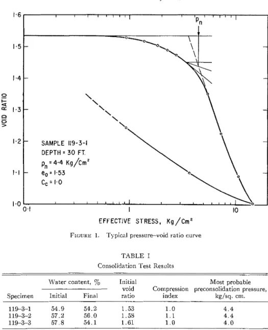
Three one-dimensional consolidation tests were performed on specimens enclosed in teflon-coated rings, 20 sq. cm. in area and 2 cm. high. Under an initial pressure of approximately 0.5 lcg/sq. cm. the specimens tended to swell when water was added so the pressure was increased immediately to a t least 0.75 kg/sq. cm. and this was sufficient to prevent swelling. The results of the three tests are given in Table I ; Figure 1 sholvs a typical pressure-void ratio curve. The most probable preconsolidation pressure is 4.4 kg/sq. cm.
(4.5 tons/sq. ft.).
*Head, Soil Mechanics Section, Division of Building Research, National Research Council, Ottawa.
227
228 C A N A D I A N GEOTECHNICAL JOUKNAL I I I 1 I , , , 'pn' I ' " 1 1 \
-
-
-
'\ - \ \ \ ' 0-
SAMPLE 119-3-1 DEPTH = 3 0 FT. pn = 4-4 ~g/crn' - e, = 1.53 Cc = 1.0 1 I I 1 l 1 1 l 0.1 I 10 EFFECTIVE STRESS, ~g /cm2FIGURE 1. Typical pressure-void ratio curve TABLE I
Consolidation Test Results
Water content, % Initial Most probable
void Compression preconsolidation pressure,
Specimen Initial Final ratio index kg/sq. cm.
All strength tests were performed on cylindrical specimens approximately
8 cm. in height and 3.6 cm. in diameter.
Unconjined Compression and Unconsolidated Undrained Triaxial Tests
These tests, carried out a t a rate of strain of lyo/min., gave consistent results a s shown in Table 11. T h e average of six tests shows the compressive strength t o be 1.7 kg/sq. cm., the undrained shear strength 0.85 kg/sq. cm. T h e soil specimens had a n average water content of 54.1 per cent. T h e failure strain in every case was just under 2 per cent.
TABLE I1 Conlpression Test Results
- -- -
Compressive Pore pressure
Water content, 0/;, strength a t failure Cell pressure Strain a t
- (01
-
03)f g 1 c failure Strain rate,Specimen Initial Final kg/sq. cm kg/sq. cm kg/sq. cm ef% %/hr.
Unconfined compression 1.70 1.69 1.76 I!~~consolidated-undrained triaxial 1.63 1.59 1 . 7 3 Consolidated-undrained triaxial 50.6 2.01 1.35 46.1 2.43 2.21 42.1 2.95 2.85
230 CANADIAN GEOTECHNICAL JOURNAL
Consolidated Undrained Tests
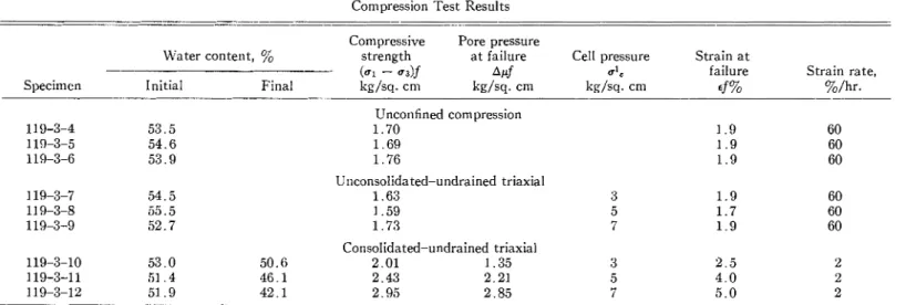
Three consolidated undrained tests were carried out a t a rate of strain of 2Y0/hr. The results are listed in Table I1 and the stress-strain and pore water pressure relationships are shown in Figure 2. Tlle Mohr stress circles a t failure for these tests are shown in Figure 3. T h e failure envelope indicates a cohesion intercept in terms of effective stresses, c' = 0.6 lig/sq. cm. and a 4' = 9".
3.5 I 1 I I I I - N E 3.0
-
0 \ rn Y LT a-
- 0 I I I I I i 0I
2 3 4 5 6 7 STRAIN, '10FIGURE 2. Relation between stress, pore water pressure, and strain for consolidated-undrained tests
Consolidated Drained Tests with A x i a l Stress Increasing
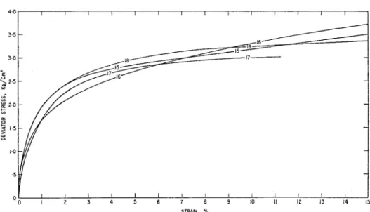
Consolidated-drained tests on four specimens strained a t rates varying from
iyo
to 2y0/hr. are listed in Table 111. Stress-strain curves for the four specimens are shown in Figure 4 up to a strain of 15 per cent. None of these tests was strained past 20 per cent and specimen 17 was strained only to 11 per cent. Some difficulty was experienced with specimen 17 and the result is therefore not averaged with the other three tests. On Figure 3, the average Mohr stressCHA~VFORD: WISNIPEG CLAY 231
EFFECTIVE STRESS, uq/CrnZ
EFFECTIVE STRESS, Kg/crnZ
F ~ c r : ~ e 3. Stress circles a t failure
circles a t strains of 10 and 20 per cent are shown. T h e stress circle, even a t 20 per cent strain, falls below the envelope for the consolidated undrained tests. This stress circle might have expanded to the envelope under further strain but it was noticed that a t 20 per cent the specimen was severely distorted.
Speciments 26 and 27 (Table 111) \?-ere completely immersed in distilled water for 4 hr. before testing. T h e ends \\-ere then retrimmed and each was weighed and measured before they were installed in the triaxial cell. Specimen 26 was then consolidated overnight under a cell pressure of 1 kg/sq. cin. and
a back pressure on the pore water of 0.85 lcg/sq. cm. Specimen 27 was con- solidated for 3 days under a cell pressure of 1.4 kg/sq. cin. and a back pressure of 0.9 kg/sq. cm. Each specimen was then strained axially under drained conditions a t 0.4 per cent per hr.
Consolidated Drained Tests with Lateral Stress Decreasing
The results of five of these controlled stress tests are shown in Table 111.
Test specimen 19 \?-as consolidated under a cell pressure of 7.3 lcg/sq. cm. The lateral stress was then decreased in decrements to G, 5, 4.5 and 4 kg/sq. cm. while the vertical stress was maintained relatively constant except during the last decrement when it was dropped t o 6.8 lcg/sq. cm. This \\;as not inten- tional but was the final computed axial stress taking into account area correc- tion. T h e time-deflection curves for the specimen under each decrement are shown in Figure 5; the Mohr stress circles for each loading decrement are also shown inset in this figure in relation t o the failure envelope from Figure 3. The failure stress circle falls slightly below the failure envelope.
Specimens 20, 22 and 23 were each consolidated under an effective stress of :3 kg/sq. cm. After consolidation, the lateral stress was decreased suddenly to 1 lcg/sq. cm. while the vertical stress was held more or less constant. Sample 20 failed during the night a t more than G hr. and less than 20 hr. after the deviator stress was applied. Specimen 23 failed 13B hr. after the deviator stress
TABLE 111
Drained Compression Test Results
-- .- -
Water content,
yo
Consolidation
End of (ul - u3)f pressure u13f u l ~
Specimen Initial consol. Final kg/sq. cm. kg/sq. cm. kg/sq. c ~ n . kg/sq. cm. Remarks
-
Consolidated-drained triaxial with axial stress increasing
110-3-1 6 54.8 42.2 37.8 4.16 7 . 3 7 . 3 11.46 strain a t f %/hr
110-3-18 54.1 43.5 40.3 3.27 7 . 3 7 . 3 10.57 strain a t $%/hr
110-3-15 53.8 43.3 41.5 3.57 7 . 3 7.3 10.87 strain a t 1 %/hr
119-3-17 54.0 42.7 41.7 3.02 7 . 3 7.3 10.32 strain a t 2%/hr
119-3-26 53.3 - 57.3 0.71 0.15 0.15 0.86 3.3% strain a t failure
110-3-27 53.3 56.6 54.8 1.08 0 . 5 0 . 5 1.58 3. 9y0 strain a t failure
Consolidated-drained triaxial with lateral stress decreasing
119-3-19 53.5 42.9 42.5 2 . 8 7.3 4.0 6 . 8
119-3-20 57.5 54.5 55.3 1.95 3 . 0 1 . 0 2.95
119-3-22 52.8 53.0 51.2 2.05 3.0 0.9 2.95
119-3-23 53.7 53.5 52.2 1.03 3 . 0 1.0 2.03
CRAWFOI<D: W I N N I P E G CLAY 233
I I I I I I I I I I I I t I 1
1 2 3 4 5 6 7 8 9 1 0 1 1 1 2 1 3 1 4 1 5
STRAIN. %
FIGUI<E 4. Stress-strain curves for drained tests-axial stress increasing
SPECIMEN 119- 3- 19
5 . 0
LOAO l
EFFECTIVE STRESS, Kg/cm'
TIME, HOURS
234 CANADIAN GEOTECHNICAL JOURNAL
was applied. Specilnen 22 had not failed after 224 hr. and so the lateral stress was decreased to 0.8 kg/sq. cm. I t then failed in 5 minutes. Each of these three specimens failed rapidly after about 2 per cent of axial strain.
Specimen 24 was consolidated under an effective stress of 1.5 kg/sq. cm. After consolidation, the axial stress was increased t o 2 kg/sq. cm. and the lateral stress was decreased t o 0.5 kg/sq. cm. Less than 1 per cent deflection occurred under this loading in 2 hr. The axial stress was then increased t o 2.2 kg/sq. cnl., the specimen deflected a further 1 per cent in 25 minutes and then failed suddenly.
All of the tests reported were made on specimens obtained from a depth of 30 ft. Most of the triaxial tests were made with cell pressures less than the preconsolidation pressure. This was done because the working effective stress range for most stability problems will be below 1.5 kg/sq. cm.
I t is of interest t h a t the Mohr failure envelope for consolidated-undrained tests (c' = 0.6 kg/sq. cm.,
4'
= 9') is confirmed to a reasonable degree byconsolidated-drained tests in which failure is induced by decreasing lateral stress. In the low stress range the drained strength is slightly greater than the
CU envelope b u t this can be attributed t o precompression. The failure envelope is compared in Figure 3 with t h a t reported by Mishtak (c' = 6.5 lb./sq. in. and
4'
= 12', Figure 5).One of the most important factors t o be investigated is the influence of time or strain rate on strength. In an attempt t o accelerate possible time-dependent softening, two specimens (26 and 27) were immersed for several hours before testing. As illustrated in Figure 3, this pretreatment caused a considerable reduction in strength under low stresses. These particular tests should be considered only t o indicate the effect of stress release with unlimited water supply. Because the supply of soil from the block was exhausted, no further tests of this nature were possible.
Tests on another block of soil from the same depth but from the opposite side of the test trench had an average compressive strength of 1.4 kg/sq. cm. Specimens immersed in de-aired distilled water for 20 hr. increased quite uni- formly in water content from 65 t o 74 per cent. I n similar specimens, tested after immersion, the compressive strength had decreased t o about 0.4 kg/sq. cm.
T h e tests reported here indicate a slightly greater shear strength in the working stress range (both total and effective stresses) than those described by Mishtak. A t higher effective stresses the opposite is true. The difference is probably due t o variation in rates of loading.
If taken a t face value these tests show a n even greater discrepancy between laboratory values and the strength required for stable slopes as reported by Mishtak. His values were approximately double the required values for test
CIIAWFORD: WINNIPEG CLAY 235 trench stability and several times the required values for the long term stability of river banks.
A few tests have shown a substantial reduction in strength when the soil is allowed t o swell. This feature imposes a restriction on the acceptability of tests carried out a t effective stress levels greater than those expected in a practical problem and in which the soil element is not permitted t o swell as it could in nature. Further tests of this nature are greatly needed.
This paper is a contribution from the Division of Building Research of the National Research Council, Canada and is published with the approval of the Director of the Division.
MISHTAK, J., 1964. "Soil Mechanics Aspects of the Red River Floodway." This JOURNAL I , no. 3: 133-146.