Publisher’s version / Version de l'éditeur:
ASTM Special Technical Publication, 193, pp. 41-53, 1958-03-01
READ THESE TERMS AND CONDITIONS CAREFULLY BEFORE USING THIS WEBSITE.
https://nrc-publications.canada.ca/eng/copyright
Vous avez des questions? Nous pouvons vous aider. Pour communiquer directement avec un auteur, consultez la
première page de la revue dans laquelle son article a été publié afin de trouver ses coordonnées. Si vous n’arrivez pas à les repérer, communiquez avec nous à PublicationsArchive-ArchivesPublications@nrc-cnrc.gc.ca.
Questions? Contact the NRC Publications Archive team at
PublicationsArchive-ArchivesPublications@nrc-cnrc.gc.ca. If you wish to email the authors directly, please see the first page of the publication for their contact information.
NRC Publications Archive
Archives des publications du CNRC
This publication could be one of several versions: author’s original, accepted manuscript or the publisher’s version. / La version de cette publication peut être l’une des suivantes : la version prépublication de l’auteur, la version acceptée du manuscrit ou la version de l’éditeur.
Access and use of this website and the material on it are subject to the Terms and Conditions set forth at
The use of a field vane apparatus in sensitive clay
Eden, W. J.; Hamilton, J. J.
https://publications-cnrc.canada.ca/fra/droits
L’accès à ce site Web et l’utilisation de son contenu sont assujettis aux conditions présentées dans le site LISEZ CES CONDITIONS ATTENTIVEMENT AVANT D’UTILISER CE SITE WEB.
NRC Publications Record / Notice d'Archives des publications de CNRC:
https://nrc-publications.canada.ca/eng/view/object/?id=d4c142fe-0e78-4db8-be01-8548e8ed9e68 https://publications-cnrc.canada.ca/fra/voir/objet/?id=d4c142fe-0e78-4db8-be01-8548e8ed9e68
S e r
TH1
N21r2 no. 52
c . 2
NATIONAL
RESEARCH
COUNCIL
C A N A D A
BLDG
DIVISION OF BUILDING RESEARCH
THE U S E O F A FIELD VANE APPARATUS
IN
SENSITIVE
CLAY
BY
W.
J.EDEN A N D
J. J.HAMILTON
REPRINT FROM AMERICAN SOCIETY FOR TESTING MATERIALS SYMPOSIUM ON I N
-
PLACE SHEAR TESTING OF SOIL BY THE VANE METHOD. A. S. T. M.SPECIAL TECHNICAL PUBLICATION NO. 193. 1957. P . 4 1
-
53.RESEARCH P A P E R NO. 52
O F T H E
DIVISION O F BUILDING RESEARCH
N R C 4490
OTTAWA
MARCH 1958
P R I C E 2 5 C E N T S
This p u b l i c a t i o n i s b e i n g d i s t r i b u t e d by t h e D i v i s i o n o f Building Research of t h e National Research Council a s a c o n t r i b u t i o n towards b e t t e r b u i l d i n g i n Canada. It should n o t be reproduced i n whole o r i n p a r t , without permission of t h e ori- g i n a l p u b l i s h e r . The D i v i s i o n would be g l a d
t o
b e of a s s i s t a n c e i n o b t a i n i n g such permission.P u b l i c a t i o n s of t h e Division of Building Research may be o b t a i n e d by m a i l i n g t h e a p p r o p r i a t e r e m i t t a n c e , ( a 3ank, Express, o r Post Off i c e Money Order o r a cheque made payable a t par i n Ottawa, t o t h e Receiver General of Canada, c r e d i t National Research c o u n c i l ) t o t h e N a t i o r a l Research Council,
Ottawa. Stamps a r e not a c c e p t a b l e .
A coupon system has been in-troduced t o
make payments f o r p u b l i c a t i o n s r e l a t i v e l y simple. Coupons a r e a v a i l a b l e i n denominations of
5,
25, and9
c e n t s , and may be o b t a i n e d by making a re- m i t t a n c e a s i n d i c a t e d above. These coupons may be used f o r t h e purchase of a l l National Research C o u n c i l p u b l i c a t i o n s i n c l u d i n g s p e c i f i c a t i o n s of t h e Canadian Government S p e c i f i c a t ions Board.Autl~orized Reprint f r o m the Copyrighted Symposium on In-Place Shear Testing of
Soil by tlie Vane hletliod
Special Tecl~nical Publication No. 193
Publ~shed by the
American Society for Testing hfaterials
1957.
ANALjJ""
L G ~T H E USE OF A FIELD VANE APPARATUS I N SENSITIVE CLAY*
BY W.
J.
EDEN' AND J. J. HAMILTON'The extremely sensitive deposits of post-glacial marine clay in the St. Law- rence lowlands have presented major difficulties in obtaining adequate undis- turbed samples for a reliable determination of shear strength. To overcome this problem, a simple field vane apparatus was devised which was readily adaptable to existing drilling equipment. This paper describes the apparatus and outlines the method of testing that has been used in the field. Shear strength values obtained are compared with those obtained from tube samples from several test holes in Leda clay. The influence of such factors as the area ratio of the vane and rod friction are discussed along with its use as a measure of sensitivity. I t is concluded that the field vane device offers a more reliable criterion for shear strength of the clay than determinations made from tube samples. Advantages and restrictions on its use are also considered.
Extensive deposits of extremely sensi- tive post-glacial Marine clay occur in the St. Lawrence and Ottawa Valleys. I t is commonly referred to as Leda clay. Investigations by Eden and Crawford
( I ) ~ have shown the Leda clays to have a moisture content in excess of the liquid limit and to be slightly precon- solidated. T o overcome the problems of obtaining detailed information on varia- tions in the deposit and of obtaining tube samples which would yield reliable shear strength determinations, a field vane apparatus was developed which was readily adaptable to existing test drilling equipment. This paper describes the apparatus, the procedure used for
*
Presented a t the Sixtieth Annual Meeting of the Society, June 16-21, 1957.Assistant Research Officer, Junior Research Officer, respectively, Division of Building Re- search, National Research Council of Canada, Ottawa Canada.
? T h e boldface numbers in parentheses refer to the list of references appended to this paper, see p. 53.
testing, and evaluates tests using the field vane compared t ) results obtained
from tube samples. Five sites were in- vestigated from which tube samples were obtained and at which continuous vane tests were conducted. T h e tube samples were obtained using a 3-in. diameter stationary piston sampler of the following critical dimensions as defined by Hvorslev (2): 24 in. in length inside diameter 2.8 in.; Kerf ratio 17.3
per cent; and inside clearance 1.2 per cent. At each of the five sites, a compre- hensive testing program was undertiken to gain a good indication of the geotech- nical properties of the deposit.
Two requirements in the operation of the vane equipment influenced its orig- inal design. These requirements were: (a) that the vane and torque measuring apparatus could be used in conjunction with a standard soil sampling drill rig,
to facilitate its use in boreholes, for soil sampling, and (b) that it could be used as a portable apparatus along with hand-operated augering equipment in areas where equipment access is difficult or impossible.
To comply with the first requirement, the diameter chosen for the vane was 2.80 in., since this size allows easy pas- sage through standard NX casing. Pre- vious investigations by Cadling and Odenstad (3) indicated that the ratio of vane length to diameter should be two, and therefore the height (or length) of vane was set a t 5.60 in.
To reduce the possibility of the vane catching on the casing and to improve its driving qualities, it was provided with conical points a t both ends. The vane has a standard A rod male coup- ling a t the upper end of its tapered shaft. The shaft was tapered in an attempt to minimize the area ratio (defined as the ratio of the average cross-sectional area of the vane to the cross-sectional area of cylinder sheared) of the vane and yet maintain the strength necessary to de- velop full design strength of the vane blades (Fig. l(a)).
Two vanes were designed, constructed, and tested. Both vanes had the same height and diameter dimensions, the principal difference being the blade thicknesses. The result of this difference in design was that the area ratio of the second-vane was considerably less than that of the first. The original vane was designed to test shear strengths up to 4
tons per sq ft and had an area ratio of 25 per cent. As work in sampling of sensitive soils indicated that disturbance was related to the area ratio of the sam- pler, it was decided to investigate the effect of varying the area ratio on shear- ing strength measured with the field vane apparatus. Consequently, the sec- ond vane was designed with an area ratio
of 10.2 per cent and capable of testing shearing strengths up to 1 ton per sq ft. The torque was applied to the drill rods through a worm gear drive mech- anism which allowed close control on the rate of angular rotation of the drill rods. The worm gear drive and crank were mounted on a frame which can be bolted to the frame of a drill rig or bolted to a reaction truss which can be anchored to the ground when used as a portable apparatus (Fig. l(b) and (6)).
Since the rotational strain in the cylinder of soil being sheared is not necessarily the same as the angular rotation of the drill rods a t ground sur- face (at least until the applied torque equals the resisting torque due to the maximum soil shearing strength), there is in effect a controlled rate of stress application until ultimate shear occurs (which results in an approximately con- trolled rate of strain). When the applied torque equals the resisting torque of the soil cylinder being sheared, the rate of strain in the soil equals the applied rate of strain a t ground surface and controlled rate of strain conditions exist. As shear progresses, the shearing resistance of the soil cylinder usually decreases and the rate of strain increases until the excess energy stored in the drill rod is dissipated to reestablish the applied and resisting torque equilibrium condition.
The torque drive allows controlled rate of angular rotations of 6 deg per min by turning the crank a t the rate of one revolution per second. This is easily accomplished and therefore good test control is maintained.
The applied torque is determined by means of a dynamometer which measures the tangential force applied to the gear sector which turns the drill rod. The axial reaction of the worm gear shaft is transmitted to this dynamometer where deflection readings are taken. Reference
44 S ~ P O S I U M ON VANE SHEAR TESTING OF S o n
to a calibration curve gives the force applied a t the known pitch radius of 13 in. By multiplying the tangential force by the pitch radius, the applied moment is determined.
The method of determining the shear formula, that is, the formula linking applied torque and the actual shearing strength measured by the vane, involved making the same assumptions as Cadling and Odenstad (3). These assumptions are :
( a ) The surface of rupture is a circu- lar cylinder surrounding the vane, with the diameter D and the height H of this cylinder equal to those of the vane, and
(b) The stress distribution a t the maximum torsional moment,
M,,,
,
is uniform across the whole surface of the cylinder, including its end surfaces.The shear formula takes the form:
T = S,K . . . (1)
where:
T = maximum applied torque,
S, = maximum or ultimate soil shearing strength, and
K = the vane constant, depending upon the physical dimensions of the vane.
Actually,
K = cylinder area times its moment arm plus cone areas times their moment arms.
For the dimensions of the NRC vane: K = 85 cu in. or 0.0492 cu ft.
Since, T = Fd where:
F = force applied on gear sector meas- ured by the dynamometer lb, and d =
gear sector pitch radius, in. (13 in.)
Fd
then, S, = -
K
where :
F is measured in pounds.
I t will be noted that no attempt has been made in this formula to correct for the effect of the resistance of "friction" that the soil offers against rotation on that portion of the vane rod below the bottom of the washed and cased hole. Since this is a variable, dependent upon the sensitivity of the soil, no simple relationship exists which would allow including a correction for this factor in this formula. The effect of "rod friction" will be further discussed later in this paper.
During the investigations, it was found that small losses in the apparatus due to friction in the bearings of the drill chuck or in the thrust bearing of the portable setup, rendered the original dynamometer calibration curve inaccu- rate, especially a t higher shearing strengths. T o eliminate this source of error, the apparatus was calibrated in simulated field test conditions through- out the desired test range. This was accomplished by a relatively simple moment arm pulley, and weight ar- rangement which allowed dynamic load- ing of the apparatus.
T o evaluate the amount of torsion that occurred in the vane rod and there- fore to study the actual stress-strain characteristics of the soil, i t was found necessary to calibrate for the angle of twist in the rods for any moment applied. I t was found that the measured and the theoretical values agreed closely and that a straight-line relationship existed, giv- ing the equation:
8 = 0.0448R.. . . .
where:
and for S, measured in Ib per sq f t the 9 = angle of twist in degrees Per foot equation becomes : of rod, and
R = dynamometer reading times 100.
stress-strain curves were derived from the test data.
Since the torque rods which turn the vane are not isolated by a casing, the test procedure must be such as to keep rod friction to a minimum. The follow- ing procedure was used in the tests reported here except for those where variations have been noted. First, a casing, large enough to pass the vane, is driven 2 ft short of the depth at which the test is to be undertaken. The casing is cleaned with a rotating washing bit. The vane is inserted into the casing and lowered to the bottom of the casing. Then, depending on the resistance of the soil, the vane is pushed into the soil until the bottom of the vane is 2 ft below the casing shoe. As the vane is advanced, care must be taken to insure that no torque is applied to the rods. In stiff soils it may be necessary to advance the vane by means of the hydraulic feed of the core drill. With the Leda class, the vane can usually be advanced by the weight of two men.
With the vane in position and the drill chuck loose, the handle of the mechanism is turned in order to obtain the inherent friction of the gear drive and the resistance of the drill rod spindle. The chuck is then tightened on the rods, and the test proceeds. The handle of the mechanism is turned a t 60 turns per min, which yields an angular rotation of the vane rods of 6 deg per mill. The dynamometer dial is read every 10 revolutions of the handle so that a stress-displacement diagram can be plotted if desired. After the maximum reading is obtained, the chuck is loosened, and the vane is rotated four revolutions as quickly as possible. After the fourth revolution is completed, the chuck is re- tightened, and the remolded strength determination proceeds 1 min after
completing the fourth revolution. The remolded strength is determined in the same manner as the undisturbed test.
Again the chuck is loosened and the vane is advanced 1 ft, and undisturbed and remolded strengths are determined. This process is repeated every foot until the vane tip is 11 ft below the bottom of the casing. The vane is withdrawn from the drill hole, the casing is advanced and washed a further 10-ft increment. Then vane tests are conducted for another 10 ft. In this manner both undisturbed and remolded strengths can be determined in 1-ft increments throughout the depth of the clay stratum.
The only way in which this procedure differs from vanes with a casing is that in all tests a length of drill rod varying from 1 to 10 f t is subjected to friction from the remolded clay upon the drill rod. With the extra sensitive Leda clay, the rod friction is insignificant in un- disturbed tests.
Rod friction can be evaluated by in- serting a drill rod fitted with a conical point into the hole and repeating the same procedure as for the remolded test. With the rod friction test, it is important to conduct the test at an interval of exactly one minute after remolding, as it has been found the Leda clays regain strength rapidly with time.
kfeasurements made to date indicate that rod friction varies from 0.35 lb to
2.5 lb per ft of drill rod.
Test results from five sites are pre- sented in Figs. 2 to 6. I n each case, con- tinuous vane tests were conducted in one boring, while 3-in. diameter tube sa~nples were obtained from another hole adja- cent to the first.
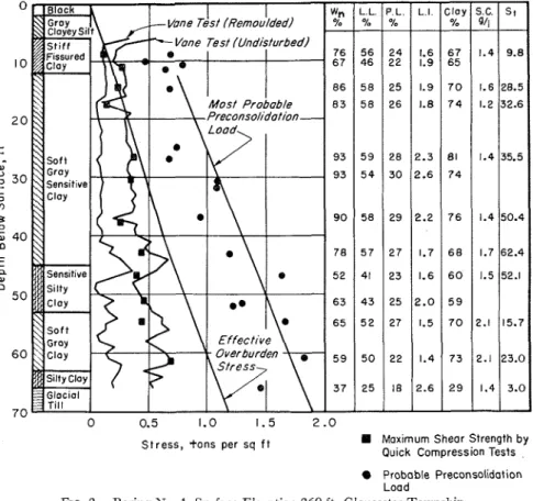
Boriftg No. I (Fig. 2) was located 11 miles southeast of the center of Ottawa in an extensive level plain where the
groundwater never falls more than 4 ft some Norwegian clays described by below the surface. Bjerrum (4).
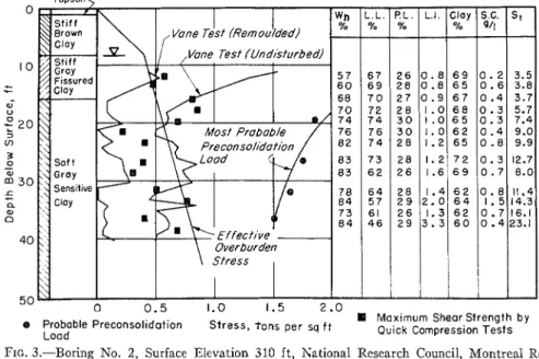
Boring No. 2 (Fig. 3 ) vvae located in Boring No. 3 (Fig. 4) was located in the eastern outskirts of Ottawa on a site the center of Ottawa, a t the site of the
0 0.5 1.0 1.5 2.0
Stress, t o n s per sq f t Maximum Shear Strength by Quick Compression Tests Probable Preconsolidation Load
FIG. 2.-Boring No. 1, Surface Elevation 260 ft, Gloucester Township.
W,= Natural water content, in per cent. L.L. = Liquid limit, in per cent.
P.L. = Plastic limit, in per cent. L.I. = Liquidity Index.
S.C. = Salt concentration, in grams per liter. St = Completely remoulded scnsitivity.
featured by frequent outcrops of bedrock National Museum previously reported by with intervening valleys filled with clay. Crawford ( 5 ) . Here the clay also had an Here the depth of clay was extremely extensive fissured crust.
variable, and the seasonal variation in Boring No. 4 (Fig. 5) was located near groundwater is from the surface to a the Upper Beauharnois Lock of the St. depth of 9 ft. The clay is fissured to a Lawrence Seaway, about 110 miles east depth of 20 to 25 f t as is the case vvith of Ottawa. This boring is located beside
EDEN AND HAMILTON ON USE IN CLAY
0 0 . 5 1.0 1.5 2 . 0
8 Moxlmum Shear Strength by Probable Preconsol~dot~on Stress, tons per sq f t
Lood Quick Compression Tests
PIG. 3.-Boring N o . 2, Surface E l e v a t i o n 310 ft, N a t i o n a l Research Council, M o n t r e a l R o a d Laboratories, Ottawa.
, "
0 0.5 1.0 1.5 2 . 0 2.5 Maximum Shear Probable Stress, t o n s per sq f t
Preconsolidation S t r e n g t h by Quick Lood Compression Tests
0 0.5 1.0 1.5 2.0
I Mox~rnurn Sheor Strength
Probable Preconsol~dot~on S t r e s s , t o n s per sq f t
Lood by Qulck Cornpress~on Tests
FIG. 5.-Boring No. 4, Surface Elevation 146.5 ft, Beauharnois, Quebec.
Proboble Preconsolidotion S t r e s s , t o n s per sq f t Quick Compression Tests Lood
the dike of the existing power canal. The construction of the dike in 1930 raised the level of the groundwater and changed the effective stresses on the clav stratum. This probably accounts for the precon- solidatioil shown in Fig. 5. Here the fissured crust extends below the depth of the original groundvriater level. The field vane tests were taken a t intervals of 13 f t in this boring.
Boring No. 5 (Fig. 6) was situated near Hawkesbury, Ontario, 60 miles east of Ottawa. This was the site of a large landslide (500,000 cu yd) which occurred in December, 1955. The clay was covered by a mantle of sand gener- ally from 8 to 10 ft thick, although it was only 4 to 5 ft at this borehole.
From each boring, except No. 3, the following properties were determined in relation to depth: natural water content,
W, Atterberg limits, L.L. and P.L., liauiditv index. L.I.. which is defined as , d
w,
-'P.L.the ratio of grain size in L.L. - P.L.'
terms of the per cent clay sized particles (less than 0.002 mm), sensitivity, S t as measured by the laboratory vane ap- paratus (expressed as the ratio of un- disturbed to remolded strengths), the pore water salt concentration (S.C.) (the amount of soluble salts in the Dore water of the clay expressed in grams per liter), unit weight, preconsolidation pressure, and unconfined or triaxial quick strengths. The results are plotted or tabulated in the form of average results for a 2-ft s a m ~ l e . The results of uncon- fined or triaxial quick results are plotted beside the diagram of vane strengths and are the maximum values obtained from a particular sample tube. In boring No. 3, no measures were made of sensi-
tivity or salt concentration.
I t is apparent from an inspection of the results of the five borings that the
strengths measured by the field vane equals or exceeds the maxinlum values of those determined in the laboratory from tube samples. The cluestion arises which method yields the more reliable data. I t should be remembered that both field vane and laboratory tests yield data ~vhicll constitute the result of a method of applying shear stresses to the clay; hence neither may represent the true shear strength under a particular set of field conditions.
The authors consider the field vane data to be more reliable than the labora- tory test methods for the shear strength of Leda clay for the following reasons:
(a) Field vane tests have proven more consistent than laboratory determina- tions, as is evident from the logs of the five borings. The fact that wide varia- tions occur in laboratory strength deter- minations within a sample tube and from one tube to another points to serious limitations in the method of sampling. The vane tests, on the other hand, are not affected to the same extent by dis- turbance, since the tests are conducted i?z silu. At Beauharnois, both the 25 and 10 per cent area ratio vanes gave very close comparison in the two adjacent boreholes. This would indicate that, in Leda clay, the most serious disturbance arises from the relief of stresses in the clay when the soil is removed from its natural environment.
(b) In two instances of landslides in Leda clay, the vane gave results close to those indicated by analysis of the slope failure, for example, those tabulated by Meyerhof ( 6 ) . I n the case of the Nicolet landslide in November, 1955, the esti- mated factor of safety based on field vane test results reported by Hurtubise and Rochette (7) was 1.1. At the Hawkes- bury landslide, Meyerhof (6) has esti- mated the shear strength to be about 800 lb per sq ft for a safety factor of 1.0. I t can be seen from Fig. 6 that this is close to the strength indicated by the
field vane. Although neither case has undisturbed strength to the remolded been reported to date in sufficient detail strength. Results presented in this paper to present conclusive evidence, the field were determined with a laboratory vane vane has in both cases proved to be apparatus. A determination was first fairly reliable. I n the case of the Hawkes- made on a cylinder of undisturbed clay
Liquidity Index
FIG. 7.-Relation Between Sensitivity and Liquidity Index.
bury slide, the vane strengths are defi- extracted from a sample tube. The clay nitely more reliable than those conducted was then completely remolded by a on tube sam~les. mechanical mixer. allowed to stand 1
min, then the remolded strength was
USE OF REMOLDED TESTS AS A determined.
MEASURE OF SENSITIVITY Both undisturbed and remolded
The sensitivities of Leda clay are strengths were determined by the field commonly 20 and sometimes exceed 100. vane, and hence a "field sensitivity" Sensitivity is defined as the ratio of the measure (ratio of undisturbed to re-
molded field vane strengths) was made in all five borings. I t was found that determinations conducted in the labora- tory on completely remolded samples were much higher than the results given by the field vane. Moreover, there was no consistent relationship between field sensitivity and the sensitivity as meas- ured in the laboratory. A study was, therefore, made of the results of sensi- tivity determinations.
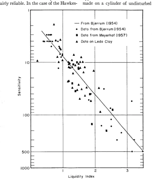
Bjerrum (4) has indicated a relation- ship between liquidity index and sensi- tivity. Figure
7
gives this relationship along with data presented by Bjerrum (4) and Meyerhof (6) together with re- sults from the five borings. I t can be seen that the determinations on Leda clay are in line with results from Norway and elsewhere. I t was concluded, there- fore, that the techniques used with the laboratory vane were coinparable to those used in Norway and that the field tests were not a reliable indication of sensitivity.The investigation was pursued further by attempting to simulate the field vane test with the laboratory vane test. First, the undisturbed strength was determined for a cylinder of soil extracted from a sample tube. The laboratory vane was then rotated quickly four revolutions. The strength of the remolded surface was then determined after 1 min rest. Finally, the sample was completely re- molded with a mechanical mixer, and the completely remolded strength was de- termined. The results of this investi- gation are presented in Table I along with the corresponding field sensitivities. From these test results it was im~ossi- ble to correlate either field sensitivity with the completely remolded sensitivity or with the partially remolded sensitivity measured by rotating the laboratory vane.
Skempton (8) was successful in ob- taining the same remolded strengths by field and laboratory methods. The clay
a t Grangemouth as reported by Skemp- ton and Northey (9) had an average value of sensitivity of 4.3, which is con- siderably less than for the Leda clays. There are two factors that have con- tributed to the discrepancies between the various test methods reported in Table I.
First, the field vane tests a cylinder of soil approximately 8 in. high and yields
TABLE I.-COMPrlRISON O F T H R E E SENSITIVITY MEASUREMENTS. (Samples 62-7 to 62-21 from Hawkesbury, boring No. 5 and samples 76-2 t o 76-13 from Beaullarnois, boring No. 4.)
average results for this height. The laboratory determinations were made on a cylinder of soil 36 in. high extracted from a tube 2 f t long. I n addition, the
Sample
xumber
"
laboratory vane is 13 in. high and hence i t is possible that the laboratory test is conduted on a strata with significantly different properties than shown by the average values for a 2-ft tube or by the field vane test. The second factor is that
Depth, f t Liqui- dity Index Comple- t e ' ~ Remo-
;:$-
tivity Field Sensl- tivity --- Sensi- tivity by R?ta-2
:
;
:
-ratory VaneLeda clay appears to stiffen or regain some of its strength significantly with time. Studies of this feature of Leda clay are not sufficiently advanced to give any other data. I t may be that hardening takes place more quickly on a remolded surface than in a completely remolded body.
Figure 7 shows that there is poor corre- lation between sensitivity and liquidity index. This would suggest that one should not attach too much significance to single values for sensitivity. I t also suggests that when presenting values for measures of sensitivity it is very im- portant to state the test method used and to note the time interval between the completion of the remolding process and the start of the strength determina- tions.
The authors do not wish to discredit the value of the remolded test but wish to suggest that the field sensitivity is no more than an indication of the sensitivity of the clay. Remolded field vane tests are valuable in pointing up changes in strata and are a good control on the ap- paratus against defective tests due to encountering a stone or poor functioning of the apparatus.
1. The results of the five site investi- gations reported indicate that the field vane apparatus provided a reasonably reliable indication of the shear strength of a sensitivity clay. For the Leda clay studied in this investigation, the authors consider the vane to give more reliable data than those obtained by conventional piston sampling and reasonably careful laboratory techniques.
2. The field vane offers considerable advantages in economy over tube sam- pling and laboratory testing. This is an important consideration where variations in soil properties are sought over a site
with a common geological history. The authors 117ould not, however, recommend that the field vane be used in the absence of other data on a clay stratum. I t is a tool with which variations in a stratum can be detected with little expenditure and should in all cases be supported by data on the other properties of the clay so that a comprehensive evaluation can be made of the clay deposit.
3. Based on the investigation of the five borings, the field sensitivity cannot be related to laboratory sensitivity de- terminations with any confidence. A
better measure of sensitivity appears to be in the relation between sensitivity and the liquidity index.
4. The remolded field vane test is useful in indicating changes in strata and provides a good control on the test- ing technique and apparatus. I t was found that the time element is impor- tant in remolded tests.
5. The apparatus reported in this paper has an element of error introduced by friction between the uncased portion of the drill rods and the remolded clay. With the highly sensitive clays reported in this paper, the rod friction is not sig- nificant. However, with similar appara- tus used in less sensitive clays, evalua- tions should be made of rod friction to guard against any discrepancies.
6. Based on a limited investigation a t boring No. 4, the difference between using field vanes with area ratios of 25 and 10 per cent is not significant.
7. The field vane described in this paper is readily adaptable to existing drilling equipment. It requires no special vane housing or casing and the rate of strain can be controlled within reasonable limits by the worm gear drive mecha- nism.
The authors wish to express their appreciation of the assistance given
them by their colleagues of the Soil Mechanics Section, Division of Building Research of The National Research Council of Canada, in the design and use of this apparatus and in the laboratory investigations undertaken. Boring No. 4 a t Beauharnois was conducted with the kind of cooperation and assistance of the
St. Lawrence Seaway Authority of Canada. Grateful acknowledgment is also made to R. F. Legget for continued encouragement in this study and with whose approval this paper is published as a contribution from the Division of Building Research, National Research Council of Canada.
REFERENCES
(1) W. J. Eden and C. B. Crawford, "Geotech- National Museum Building," Proceedings,
nical Properties of Leda Clay in the Ottawa 3rd International Conference on Soil Me- Area," Proceedings, 4th International Con- chanics and Foundation Engineering, Vol. ference on Soil Mechanics and Foundation 1, pp. 338-345 (1953).
Engineering, London (1957) (in press). (6) G. G. Meyerhof, "The Mechanism of Flow (2) M. J. Hvorslev, "Subsurface Exploration and Slides in Cohesive Soils," Gioteclrniqt~e, Vol.
Sampling of Soils for Civil Engineering 7, No. 1, pp. 41-49 (1957).
Purposes," The Engineering Foundation, (7) J. E. Hurtubise and P. A. Rochette, "Causes New York, N. Y. (1949). of Landslides as Revealed by Study of
(3) Lyman Cadling and Sten Odenstad, "The Nicolet Disaster," Roads and Engifzeering
Vane Borer: An Apparatus for Determin- Construction, Vol. 95, No. 3, pp. 82-89 ing the Shear Strength of Clay Soils Di- (1957).
rectly in the Ground," Proceedings, No. 2, (8) A. W. Skempton, "Vane Tests in the Alluvial Royal Swedish Geotechnical Inst., Stock- Plain of the River Forth near Grange- holm (1950). mouth," GEotechnique, Vol. 1, No. 2, pp. (4) L. Bjerrum, "Geotechnical Properties of 111-124 , London (1948).
Norwegian Marine Clays," G6otechniq1te, (9) A. W. Skempton and R. D . Northey, "The Vol. 4, No. 2, pp. 49-69 (1954). Sensitivity of Clays," Giotechniqz~e, Vol. 3, (5) C. B. Crawford, "Settlement Studies on the No. 1, pp. 30-53 (1952).
C ~ K. B. WOODS.'-I might mention that we used apparatus similar N to the author's in an attempt to evaluate some of the banded sediments on the lower reaches of the St. Lawrence this last summer and we have been well pleased with the performance of the equipment and the data obtained.
A