HAL Id: hal-01225782
https://hal.archives-ouvertes.fr/hal-01225782
Submitted on 9 Nov 2015
HAL is a multi-disciplinary open access
archive for the deposit and dissemination of
sci-entific research documents, whether they are
pub-lished or not. The documents may come from
teaching and research institutions in France or
abroad, or from public or private research centers.
L’archive ouverte pluridisciplinaire HAL, est
destinée au dépôt et à la diffusion de documents
scientifiques de niveau recherche, publiés ou non,
émanant des établissements d’enseignement et de
recherche français ou étrangers, des laboratoires
publics ou privés.
Investigations on an All-Tunable Fiber Ring Resonator
Khaldoun Saleh, Arnaud Fernandez, Olivier Llopis
To cite this version:
Khaldoun Saleh, Arnaud Fernandez, Olivier Llopis. Investigations on an All-Tunable Fiber Ring
Resonator. Optics Communications, Elsevier, 2016, 359, pp. 261-267. �hal-01225782�
Investigations on an All-Tunable Fiber Ring Resonator
K. Saleh*, A. Fernandez, O. Llopis
CNRS, LAAS, Université de Toulouse, 7 Avenue du Colonel Roche, 31077 Toulouse, France *Now at FEMTO-ST Institute (UMR CNRS 6174), 25030 Besançon, France
Corresponding author: khaldoun.saleh@femto-st.fr
Abstract
The architecture of an all-tunable optical fiber ring resonator is described in detail in this paper. This architecture has been firstly modeled using an original CAD approach. The simulation results demonstrate a total control of both the absolute frequency and the free spectral range of the final optical resonance comb generated by the optical resonator. The different experimental setups used to characterize the tunable resonator are described and the obtained results proving the concept are also provided.
Keywords: fiber ring resonator; tunable optical filters; frequency reference; microwave photonics; CAD of microwave optical systems
1. Introduction
Tunability is a desired feature in any optical filter [1]. This also applies to the fiber ring resonator (FRR) case due to the high optical quality factor (QOpt) that can be obtained and to the simplicity in its fabrication [2]. Indeed, the FRR is a very useful element for many applications as it can be used as a high selectivity add-drop optical filter, a high resolution gyroscope, a fiber laser etc. We can particularly mention the phase noise performance that can be achieved for microwave signals generated by an optoelectronic oscillator (OEO) when a high QOpt FRR is used as the frequency stability element in the oscillator setup [3]. Besides the importance of achieving high spectral purity for the generated microwaves, the tunability is also greatly desired in OEOs. For that reason, numerous studies have been performed to tune the oscillation frequency in different OEO’s architectures [4, 5, 6].
Certainly, tuning the FRR’s frequency response is possible by changing the resonator’s temperature or by using the effect of polarization and birefringence in the resonance loop [7]. On the one hand, the FRR’s response to the temperature is too weak and it is also very slow. In a previous work, [2], we have performed a detailed study on this matter. It has been found, for example, that the FSR response to the temperature in a 20m-long FRR is equal to |70𝐻𝑧|/𝐾. This means that a temperature variation of ∆𝑇 = 1.4 × 10⁵𝐾 is
theoretically required to tune the FRR’s frequency response by a full FSR (FSR ≈ 10 MHz in a 20m-long FRR), which is clearly impractical to achieve. On the other hand, the effect of polarization and birefringence is limited and could be sensitive to external perturbations.
In this paper, we first give a brief description of the FRR and later on we present our theoretical and experimental investigations on a particular architecture of the FRR. This architecture is principally based on the enclosure of a phase shifter and a tunable optical coupler (forming a Sagnac mirror) at the same time in a double coupler add-drop FRR. While some research works studying separately similar architectures were reported in the literature [8, 9, 10, 11], to our knowledge, no detailed study has been performed to show the effect of the combination of both the phase shifter and the tunable optical coupler on the double coupler add-drop FRR’s response. In the present work, our investigations show that such combination allows a complete tuning of the absolute frequency of the generated final optical resonance comb (ORC) and of its free spectral
range (FSR) as well. In addition, the results of a study performed on the possibility of tuning independently both of these characteristics of an ORC are also addressed.
2. Fiber ring resonator
The architecture of the double-direct-coupled FRR, considered in our studies, is shown in Fig. 1(a). This FRR is fabricated using two low loss two-by-two directional optical fiber couplers (C1 and C2) linked together
with a single-mode fiber loop. The resonator generates a transverse single ORC with microwave spacing called FSR. The FSR is given by FSR = c/nL, where (L) the fiber loop length, (n) is its refractive index and (c ~ 3.108 m/s) is the light speed in free space. The Q
Opt of this resonator particularly depends on the couplers’ coupling coefficients (κ1 for C1 and κ2 for C2) and on the overall losses in the resonator architecture: couplers’
excess loss (γ1,2), splices’ loss (αs) and fiber linear loss (αf).
Fig. 1. (a) Architecture of the double-direct-coupled FRR (a phase-shifter is inserted to control the phase delay inside the FRR’s loop. (b) ADS model of the FRR
3. Absolute frequency tuning using an optical phase-shifter
As already reported in [8], it is possible to tune the absolute frequency of an ORC generated by a FRR by inserting an optical phase-shifter (PS) within the FRR’s loop [see Fig. 1(a)]. The PS enables the control of the
Output 3 (transmission) Output 2 (transmission) Output 1 (absorption) Input Laser carrier C1 C2 Phase shifter FSR
(a)
(b)
phase delay inside the ring loop and, therefore, the control of the phase matching condition. An additional phase-shift added inside the FRR’s loop (ΔφPS) will lead to a proportional absolute frequency shift (ΔfOpt; fOpt being the optical resonant frequency) in the ORC as follows, [8]:
2
2
PS PS Optc
f
FSR
nL
From the above relation, we can clearly notice that when an additional 2π rad phase-shift is added to the optical signal inside the FRR’s loop, the resonant frequency will shift by one complete FSR. In order to simulate the response of such FRR architecture, we have used an upgraded version of a model of the FRR developed in a previous work [12]. This FRR model is based on an original approach using electronic design software (ADS from Agilent), typically used for microwave systems’ design. With this FRR’s model [depicted in Fig. 1(b)], we have been able to simulate the transmission response of a 20m-long FRR including a phase-shifter. Consequently, the abovementioned frequency tuning technique has been confirmed by changing ΔφPS from 0 to 2π while monitoring the FRR’s responses (see Fig. 2; for clarity’s sake, the presented results are for a change in ΔφPS’s value by π). Furthermore, we have found that such a tuning technique does not modify the FRR’s transmission characteristics (insertion loss (IL), QOpt, etc…).
Fig. 2. Transmission spectrum at the third output of a 20m-long FRR simulated, using an ADS model, while changing ΔφPS’s value by π
rad. An absolute frequency shift of the ORC by one half of the FSR is obtained
The abovementioned theory on the optical absolute frequency shift has been experimentally confirmed using a narrow linewidth laser and the wavelength scanning technique [13]. This wavelength scanning technique consists of a frequency fine-tuning of a narrow linewidth (~1 kHz) Koheras fiber laser to explore the FRR’s ORC by recording the FRR’s response on a photodiode followed by an oscilloscope. In our experimental setup, we have used a 23m-long FRR including a PS (abbreviated by FRR-PS) and a second 20m-long FRR as a spectator to witness the absolute frequency shift in the FRR-PS’s ORC (see Fig. 3). The results are depicted in Fig. 4 and they confirm that when an additional phase-shift ΔφPS = π is added inside the FRR-PS’s loop, its ORC shifts by FSR/2.
S21
magni
tude (dB)
Fig. 3. Experimental setup used to detect the absolute frequency shift in a FRR-PS’s ORC. RUT: resonator under test; C3dB: 3dB directional optical coupler; PD: photodiode
Fig. 4. Absolute frequency shift by FSR/2 in the FRR-PS’s ORC (in yellow) occurred when an additional phase-shift ΔφPS = π was added
inside the 23m-long FRR-PS’s loop. The second 20m-long FRR (in green) has been used as a spectator ring resonator to witness this absolute frequency shift
Output 3 (transmission) Input C1 C2 23m-long FRR (RUT) Output 3 (absorption) Input C1 20m-long FRR (spectator) Function generator Piezoelectric transducer
PD
PD
C3dB Koheras laser Oscilloscope 1 2 1’ 2’ 23m-long FRRAmpl
itud
e
(a.u
.)
Time (a.u.)
Reference Reference 23m-long FRR 20m-long FRR 20m-long FRR4. Free spectral range tuning using a variable optical coupler
A fiber loop mirror (FLM), or a Sagnac reflector [14], is a device made by connecting the ports on one side of a two-by-two fibred directional optical coupler. This FLM is usually used in its simplest form as a reflecting device [15]. In that case, the input optical signal is split so that two counter-propagating waves are formed in the fiber loop, which then return to recombine (interfere) at the coupler. Since the optical paths for both counter-propagating waves in the loop are the same, the reflectivity of the FLM will be only determined by the coupling ratio of the optical coupler (if the thermal effects and the polarization rotation inside the fiber are disregarded).
In our case, the same effect has been used to tune the ORC’s FSR. This has been achieved in a configuration based on a classical FRR architecture including a FLM inside its loop (abbreviated by FRR-FLM). The FLM, of a length LFLM, has been made by connecting the ports on one side of a tunable optical coupler (TC) [see Fig. 5(a)]. A similar architecture to this FRR-FLM has been studied in [9, 10], where analytical expressions have been derived for a tunable single-direct-coupled ring resonator. Also, in [11], the effect of the Sagnac phase-shift by the rotation of the Sagnac loop on the single-direct-coupled ring resonator’s response has been studied. In our studies, however, the case of an all-tunable double-direct-coupled FRR is considered and investigated in detail. As we will see later this section, this has allowed us to point out many important differences in the characteristics of the second and third outputs of the FRR-FLM. Moreover, the use of a tunable coupler seems to be a robust way to benefit from the Sagnac effect in the FRR-FLM.
In the FRR-FLM that we have designed and studied, we have found that the optical resonance can experience a split leading to the creation of a new ORC. This split value (Δs), or what we can call the new ORC’s absolute frequency shift from the main ORC, was depending on the TC’s coupling coefficient (κTC). By tuning κTC from 0 to 100 %, we were able to adjust Δs from zero to one complete FSR in the FRR-FLM. Here it is noteworthy that the FSR for both main and new ORCs in the FRR-FLM is the same. This FSR is given by FSRFRR-FLM = c/n(LFRR+LFLM), where LFRR is the FRR’s length excluding the FLM.
Based on our FRR’s ADS model, we have developed a model of the FRR-FLM, with an 18m-long FRR and a 2m-long FLM [see Fig. 5(b)]. We have considered a 0.5 dB/km fiber loss (Af) because polarization maintaining fibers have been used in order to get a stable polarization behavior of the optical carrier inside the FRR-FLM [3]. The excess losses for the three couplers used were considered as the following: γ1 = γ2 = γTC = 0.03 dB (all these values can be technically achieved). Moreover, an optimal optical coupling has been found for couplers C1 and C2 (κ1= κ1= 8%), allowing to obtain the best achieved transmission characteristics for the FRR-FLM (i.e. low IL, high QOpt, etc…) [3]. The optical transmission spectrum at both second and third outputs of the FRR-FLM has been simulated while changing κTC’s value from 1 to 100 %. For clarity’s sake, in Fig. 6 we only show the simulation results obtained for κTC = 1% and for κTC = 50%. From these results we can notice that the main ORC will remain fixed while the new ORC is uniformly shifted when changing κTC’s value. This particularly interesting FRR-FLM’s behavior has not been reported in [9, 10]. In [9, 10], the authors predict that each ORC will experience an equal but opposite frequency shift which also depends on the coupling coefficient κTC but spans a value from 0 to ±FSR/2 when κTC’s value varies from 0 to 100 %. Our simulation results show that a frequency shift by FSRFRR-FLM/2 is observed for the new ORC when κTC’s value is equal to 50 %. This observed behavior is crucial for many applications if one needs to keep one ORC fixed while tuning the other. On the other hand, if one takes into account the amount of the frequency split reported in [10] in function of κTC’s value, the reported results agree with the results obtained using our model: a frequency split that is equal to a complete FSR is obtained when κTC is equal to 100 %.
Aside from that, the results in Fig. 6 show that the combs at the FRR-FLM’s second and third outputs seem to have different characteristics. For that reason, we have compared both outputs’ characteristics versus κTC’s value, particularly regarding the main and new resonances’ full width at half maximum (FWHM), IL and worst-case out-of-band rejection (see Fig. 7).
Fig. 5. (a) Architecture and (b) ADS model of the FRR including a fiber loop mirror (FRR-FLM). A phase shifter can be inserted into the fiber loop mirror in order to get an all-tunable FRR (TFRR; see section 6)
The simulation results presented in Fig. 7(a) show that, at both outputs, the FWHM is the same for the main and the new ORC. However, they show that a narrower FWHM can be obtained at the FRR-FLM’s third output on a wider range of κTC’s variations. This FWHM is in the range of 345 kHz, resulting in a QOpt of 5.6x10⁸ at a laser wavelength λ
l = 1.55 µm. Likewise, the results in Fig. 7(b) show that, for both outputs, the transmission loss is the same for the main and the new ORC. On the other hand, a constant transmission loss can be obtained at the FRR-FLM’s second output versus κTC (transmission loss = 8.6 dB), which is not the case at the FRR-FLM’s third output. Indeed, the transmission loss at the third output varies from 8 dB to 9.1 dB versus κTc, which is still acceptable if we take into account the behavior of the FWHM and the worst-case out-of-band rejection of the resonances at the third output. Fig. 7(c) results show that, for both outputs, the worst-case out-of-band rejection is the same for the main and the new ORC. However, a higher out-of-band rejection can be obtained at the FRR-FLM’s third output on a wider range of κTC’s variations.
Output 3 (transmission) Input
C
1C
2 Output 2 (transmission) Output 1 (absorption)Fiber loop mirror Tunable
coupler
LFRR LFLM
(b)
(a)
Fig. 6. Optical transmission spectrum at both (a) second and (b) third outputs of the FRR-FLM simulated, using an ADS model, while changing κTC’s value. ↑ and↓ notations indicate an increasing or a decreasing κTC’s value
-50 -45 -40 -35 -30 -25 -20 -15 -10 -5 0 S21 magni tude (dB ) Normalized frequency (MHz) 1% 50% (KTC=50%) 5,1 MHz = (FSR/2) Fixed resonance Moving resonances (Tunable new ORC)
Fixed resonance (200 THz) Fixed comb (FSR=10,2 MHz) (K↓) (K↑) -31 -28 -25 -22 -19 -16 -13 -10 -7 -4 S21 magni tude (dB ) Normalized frequency (MHz) 1% 50% Fixed comb (FSR=10,2 MHz) (KTC=50%) 5,1 MHz = (FSR/2) Fixed resonance Moving resonances (Tunable new ORC)
Fixed resonance (200 THz) (K↓) (K↑)
(a)
(b)
Fig. 7. Transmission characteristics of the FRR-FLM, at both second and third outputs, for the main and the new ORC, simulated versus κTC’s value: (a) FWHM, (b) transmission loss and (c) worst-case out-of-band rejection
343 344 345 346 347 348 349 0% 20% 40% 60% 80% 100% FW HM (k Hz ) KTC(%)
Out2 - Main ORC Out3 - Main ORC Out2 - New ORC Out3 - New ORC
Out2 Out3 7.6 8 8.4 8.8 9.2 0% 20% 40% 60% 80% 100% T ransmi ssion loss (dB ) KTC(%)
Out2 - Main ORC Out2 - New ORC Out3 - Main ORC Out3 - New ORC Out2 Out3 0 5 10 15 20 25 0% 20% 40% 60% 80% 100% W orst -case rejection (dB) KTC(%)
Out2 - Main ORC Out3 - Main ORC Out3 - New ORC Out2 - New ORC Out2
Out3
(a)
(b)
5. Experimental results for a FRR-FLM
In order to experimentally confirm the aforementioned theoretical results, we have fabricated a FRR-FLM with some optical devices available at our laboratory. To this purpose, we have firstly characterized a polarization-maintaining variable-ratio optical coupler. This TC’s coupling coefficient was adjustable by two different means: a fast tuning, by means of a micrometric screw, and a fine tuning that is remotely controlled using a piezoelectric actuator. The main drawback of this device was its high excess loss [~20% (~1 dB)]. Moreover, the TC’s outputs were not well equilibrated and the TC was not hysteresis-free.
Here, it is noteworthy that this FRR-FLM was made for a single test. Therefore, fiber connectors were used to connect the different optical devices in the FRR-FLM instead of splicing them. Moreover, the input and output couplers of the FRR part in the FRR-FLM had the following characteristics: κ1 = κ2 = 30 % (no 8% couplers were available at the laboratory to achieve an optimal coupling in the FRR-FLM) and γ1 = γ2 = 0.1
dB. As a result, the fabricated FRR-FLM had very high transmission loss [see Fig. 5(a)]. This FRR-FLM was 7m-long (LFRR = 5 m and LFLM = 2 m), resulting in a theoretical FSRFRR-FLM of about 29 MHz.
Once fabricated, the 7m-long FRR-FLM has been characterized using a microwave frequency domain characterization technique (see the illustration in Fig. 8). To be able to use this technique, the laser carrier must be first stabilized onto the center of one of the FRR-FLM’s optical modes. This is achieved using the Pound-Drever-Hall laser stabilization technique [16]. Later on, the laser carrier is modulated by means of a frequency-shifter modulator (FSM) driven by a sweeping radio frequency (RF) signal delivered by a microwave vector network analyzer (VNA). As a result, the obtained sweeping single modulation sideband (MSB) will explore the different optical modes of the FRR-FLM. Later on, the beat note of the laser carrier and this optical MSB on a fast photodiode will transcribe the FRR-FLM’s transmission characteristics in the RF domain on a given frequency bandwidth. This is done by measuring the S21 transmission parameter on the VNA. More details on this microwave frequency domain characterization technique can be found in [17].
Fig. 8. Illustration of the microwave frequency domain characterization technique. This illustration shows the importance of using a FSM to modulate the laser carrier in order to generate a single sweeping MSB (rather than two MSBs if a classical linear amplitude modulation of the optical carrier is used) and therefore accurately transcribe the transmission characteristics of a TFRR (or a FRR-FLM) in the RF domain on a given frequency bandwidth
In order to correctly characterize the FRR-FLM in the microwave frequency domain, it is essential to use the FSM. In point of fact, the optical resonances belonging to the main and the new ORC in the FRR-FLM are not equidistant regarding each other (see the illustration in Fig. 8). Therefore, if a classical linear amplitude modulation of the optical carrier is used, this will result in a deformation of the RF response. This is because, in that case, two MSBs are generated, that will not overlap at the same time with two optical resonances
Output 3 (transmission)
1 2 3 4 5 6 7
Δs
Port-1
Vector network analyzer
Port-2 Laser Sweeping single MSB Laser carrier Sweeping RF signal Photodetector S21 magnitude RF Second MSB 1 2 3 4 5 6 7 FSM Main ORC New ORC Δs
Optical spectrum at the third output of a TFRR Input
belonging each to a different ORC of the two ORCs generated by the FRR-FLM. On the contrary, the FSM produces only one optical MSB besides the optical carrier. Consequently, it is possible to stabilize the laser carrier onto one of the optical resonances of the main ORC (ideally) where the single optical MSB will therefore properly explore the other resonances of the two ORCs generated by the FRR-FLM and accurately transcribe them in the microwave frequency domain.
Fig. 9. Absorption output of a 7m-long FRR-FLM characterized using the microwave frequency domain characterization technique
Aside from that, the transmission loss was always high, thus preventing a correct description of the FRR-FLM’s transmission characteristics. Yet, we were still able to describe the FRR-FRR-FLM’s absorption characteristics using our microwave characterization bench because we were able to detect more optical power at the absorption port of the FRR-FLM [the FRR-FLM’s first output; see Fig. 5(a)]. The S21 transmission parameter measurements are presented in Fig. 9. These results are in very good agreement with the theory as they confirm a total FSRFRR-FLM of 31 MHz and, particularly, a frequency shift in the new ORC by half of the FSRFRR-FLM when κTC’s value is around 50%. The observed difference in the absorption resonances’ depths is likely due to the non-equilibrated outputs of the variable optical coupler we were using.
Likewise, the 7m-long FRR-FLM has been characterized in the optical domain using a narrow linewidth laser and the wavelength scanning technique [13]. Because of the high transmission loss issue, an optical amplifier had been added at the FRR-FLM’s third output and we were therefore able to measure the transmitted signal while changing κTC’s value (κTC = 1%, 30%, 70 % and 87 %). The measurements are depicted in Fig. 10 and they show a qualitatively good agreement with our theoretical predictions on the new ORC’s tunability versus κTC in a FRR-FLM. The amplitude deformation in the transmitted signal is most probably due to the non-equilibrated outputs of the variable coupler we were using.
Finally, we can establish that these different theoretical and experimental studies strongly confirm the feasibility of an all-tunable FRR. Obviously, the 7m-long FRR-FLM that we have experimentally characterized was a non-optimized test-resonator used only to validate what our ADS models predicted on the FRR’s tunability. Such an all-tunable FRR is certainly very advantageous for many applications in the microwave photonics field (e.g. narrow bandwidth tunable filter, tunable OEO, etc…), particularly if the resonator characteristics can be improved in terms of losses.
-30 -25 -20 -15 -10 -5 0 10.13 10.14 10.16 10.17 10.18 10.20 10.21 S21 ma gn itu de (dB) Frequency (GHz) K-TC around 1 % K-TC around 50 % 16.7 MHz (~FSR/2) FSR = 31.1 MHz KTC~1% KTC~50%
Fig. 10. Transmitted optical signal measured at the third output of the 7m-long FRR-FLM, using the laser wavelength scanning technique, for different κTC’s values: 1%, 30%, 70 % and 87 %. The 2.6 s timescale (or visualization window) on this graphic represents a
96 MHz laser frequency scanning range
6. All-tunable FRR
The simulation results of section 4 and the experimental results of section 5 are very interesting as they predict, together with section 3’s simulation and experimental results, that an all-tunable FRR (TFRR) can be designed if we combine the tunable coupler effect with the phase-shifter effect in the same FRR. This TFRR architecture therefore includes a FLM and a PS as illustrated in Fig. 5(a). Here, it is noteworthy that our model predicts exactly the same TFRR’s transmission characteristics either when the PS is inserted inside the FLM’s loop or inside the FRR’s loop.
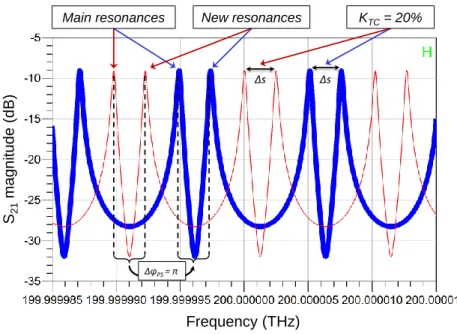
The optical transmission spectrum at the third output of a 20m-long TFRR has been therefore simulated using an ADS model. The results are presented in Fig. 11 and they show that a tuning of the new ORC’s absolute frequency is obtained by changing the coupling coefficient of the tunable coupler. Also, independently, a uniform tuning of both the new and main ORCs’ absolute frequencies is obtained by changing the phase-shift added by the phase-shifter.
Unfortunately such TFRR structure has not been experimentally tested. This was due to the high insertion losses introduced by the PS inside the TFRR. Still, the theoretical and experimental results in this article proves that if one is able to design a TFRR with low loss devices or technology (e.g. a phase shifter and a tunable optical coupler in integrated ring resonators), a complete tunability of the resonator can be obtained as expected in Fig. 11. 0 5 10 15 20 25 30 35 40 0.0 0.2 0.4 0.6 0.8 1.0 1.2 1.4 1.6 1.8 2.0 2.2 2.4 2.6 Ampli tude (mV) Time (s) K around 1% K around 30% K around 70% K around 87% 1% 1% 30% 30% 70% 70% 87% 87% ~ FSR ~0.93 FSR ~0.66 FSR ~0.3 FSR
Fig. 11. Optical transmission spectrum at the third output of a 20m-long TFRR, simulated using an ADS model. A tuning of the new ORC’s absolute frequency is obtained by changing the coupling coefficient of the tunable coupler. Independently, a uniform tuning of both the new and main ORCs’ absolute frequencies is obtained by changing the phase-shift added by the phase-shifter
7. Conclusion
In this paper, the optical fiber ring resonator (FRR) tunability has been theoretically studied in detail and we have been able to demonstrate a full tunability of the FRR response. This has been achieved in a particular resonator architecture based on the addition of an optical phase-shifter and a fiber loop mirror inside the FRR’s loop. In this architecture, the absolute frequency and the free spectral range of the optical resonance comb generated by the resonator could be both changed independently. This all-tunable FRR has been modeled and a large part of the theoretical results were later on qualitatively validated through different experimental tests. Such an all-tunable FRR can be certainly advantageous for many applications in the microwave photonics field. Our ongoing researches are currently focused on the full experimental characterization of such all-tunable FRR.
Acknowledgements
This work has been supported by the French national research agency (ANR) and the “Direction Générale de l’Armement” (DGA), French MoD procurement agency, under the project ANR-11-ASTR-0029 MINOTOR.
References
1. D. Sadot, E. Boimovich, Tunable optical filters for dense WDM networks, IEEE Communications Magazine 36 (1998) 50-55.
Main resonances New resonances KTC= 20%
ΔφPS= π S21 mag ni tud e (dB) Frequency (THz) Δs Δs
2. K. Saleh, A. Bouchier, P. H. Merrer, O. Llopis, G. Cibiel, Fiber ring resonator based opto-electronic oscillator: phase noise optimisation and thermal stability study, Proc. SPIE 7936 RF and Millimeter-Wave Photonics (2011) 79360A.
3. K. Saleh, O. Llopis, G. Cibiel, Optical scattering induced noise in fiber ring resonators and optoelectronic oscillators, J. Lightw. Technol. 31 (2013) 1433-1446.
4. I. Ozdur, D. Mandridis, N. Hoghooghi, P.J. Delfyett, Low noise optically tunable opto-electronic oscillator with fabry–perot etalon, J. Lightw. Technol. 28 (2010) 3100-3106.
5. A. Savchenkov, V. Ilchenko, W. Liang, D. Eliyahu, A. Matsko, D. Seidel, L. Maleki, Voltage-controlled photonic oscillator, Opt. Lett. 35 (2010) 1572-1574.
6. J. Maxin, G. Pillet, B. Steinhausser, L. Morvan, O. Llopis, D. Dolfi, Widely tunable opto-electronic oscillator based ona dual-frequency laser, J. Lightw. Technol. 31 (2013) 2919-2925.
7. F.E. Seraji, F. Asghari, S.A. Yekrangi, Tunability of optical filter based on fibre-optic ring resonator using polarisation and birefringence effects in the resonator loop, Ukrainian journal of physical optics 11, (2010) 185-192.
8. D. Sadot, Ultra‐fast tunable fiber‐loop optical filters for dense WDM applications, WDM Technology and Applications IEE Colloquium (1997) 13/1‐13/5.
9. C. Vazquez, S. Vargas, J.M.S. Pena, P. Corredera, Tunable optical filters using compound ring resonators for DWDM, IEEE Phot. Technol. Lett. 15 (2003) 1085-1087.
10. C. Vazquez, S.E. Vargas, J.M.S. Pena, Sagnac loop in ring resonators for tunable optical filters, J. Lightw. Technol. 23 (2005) 2555- 2567.
11. F.E. Seraji, Fatemeh Asghari, Tunable optical filter based on Sagnac phase-shift using single optical ring resonator, Optics & Laser Technology 42 (2010) 115-119.
12. K. Saleh, P.H. Merrer, A. Ali-Slimane, O. Llopis, G. Cibiel, Study of the noise processes in microwave oscillators based on passive optical resonators, Int. J. Microw. Wir. Technol. 5 (2013) 371-380.
13. O. Llopis, P. H. Merrer, A. Bouchier, K. Saleh, and G. Cibiel, High-Q optical resonators: characterization and application to stabilization of lasers and high spectral purity microwave oscillators, Proc. SPIE 7579 Laser Resonators and Beam Control XII (2010) 75791B.
14. T. Birks, P. Morkel, Jones calculus analysis of single-mode fiber Sagnac reflector, Appl. Opt. 27 (1988) 3107-3113.
15. S. Feng, Q. Mao, L. Shang, J. W.Y. Lit, Reflectivity characteristics of the fiber loop mirror with a polarization controller, Opt. Commun. 277 (2007) 322-328.
16. E. Black, An introduction to Pound-Drever-Hall laser frequency stabilization, Am. J. Phys. 69 (2001) 79–87.
17. P. Merrer, K. Saleh, O. Llopis, S. Berneschi, F. Cosi, G. Nunzi Conti, Characterization technique of optical whispering gallery mode resonators in the microwave frequency domain for optoelectronic oscillators, Appl. Opt. 51 (2012) 4742-4748.