HAL Id: hal-00317212
https://hal.archives-ouvertes.fr/hal-00317212
Submitted on 1 Jan 2004
HAL is a multi-disciplinary open access
archive for the deposit and dissemination of
sci-entific research documents, whether they are
pub-lished or not. The documents may come from
teaching and research institutions in France or
abroad, or from public or private research centers.
L’archive ouverte pluridisciplinaire HAL, est
destinée au dépôt et à la diffusion de documents
scientifiques de niveau recherche, publiés ou non,
émanant des établissements d’enseignement et de
recherche français ou étrangers, des laboratoires
publics ou privés.
EMMA - the Electric and Magnetic Monitor of the
Aurora on Astrid-2
L. G. Blomberg, G. T. Marklund, P.-A. Lindqvist, F. Primdahl, P. Brauer, L.
Bylander, J. A. Cumnock, S. Eriksson, N. Ivchenko, T. Karlsson, et al.
To cite this version:
L. G. Blomberg, G. T. Marklund, P.-A. Lindqvist, F. Primdahl, P. Brauer, et al.. EMMA - the Electric
and Magnetic Monitor of the Aurora on Astrid-2. Annales Geophysicae, European Geosciences Union,
2004, 22 (1), pp.115-123. �hal-00317212�
Annales
Geophysicae
EMMA – the Electric and Magnetic Monitor of the Aurora
on Astrid-2
L. G. Blomberg1, G. T. Marklund1, P.-A. Lindqvist1, F. Primdahl2,3, P. Brauer2, L. Bylander1, J. A. Cumnock1,4, S. Eriksson1,5, N. Ivchenko1, T. Karlsson1, A. Kullen1, J. M. G. Merayo2, E. B. Pedersen6,7, and J. R. Petersen2,3
1Alfv´en Laboratory, Royal Institute of Technology, Stockholm, Sweden 2Ørsted DTU, Technical University of Denmark, Lyngby, Denmark 3Danish Space Research Institute, Copenhagen, Denmark
4Also at University of Texas at Dallas, Richardson, TX, USA 5Now at University of Colorado, Boulder, CO, USA
6TERMA Electronics AS, Lystrup, Denmark 7Now at Ericsson Telebit A/S, Viby J., Denmark
Received: 30 December 2002 – Revised: 26 April 2003 – Accepted: 28 May 2003 – Published: 1 January 2004
Abstract. The Astrid-2 mission has dual primary objectives.
First, it is an orbiting instrument platform for studying au-roral electrodynamics. Second, it is a technology demon-stration of the feasibility of using micro-satellites for innova-tive space plasma physics research. The EMMA instrument, which we discuss in the present paper, is designed to pro-vide simultaneous sampling of two electric and three mag-netic field components up to about 1 kHz. The spin plane components of the electric field are measured by two pairs of opposing probes extended by wire booms with a sepa-ration distance of 6.7 m. The probes have titanium nitride (TiN) surfaces, which has proved to be a material with excel-lent properties for providing good electrical contact between probe and plasma. The wire booms are of a new design in which the booms in the stowed position are wound around the exterior of the spacecraft body. The boom system was flown for the first time on this mission and worked flawlessly. The magnetic field is measured by a tri-axial fluxgate sensor located at the tip of a rigid, hinged boom extended along the spacecraft spin axis and facing away from the Sun. The new advanced-design fluxgate magnetometer uses digital signal processors for detection and feedback, thereby reducing the analogue circuitry to a minimum. The instrument character-istics as well as a brief review of the science accomplished and planned are presented.
Key words. Ionosphere (auroral ionosphere). Magne-tospheric physics (magnetosphere-ionosphere interactions). Space plasma physics (instruments and techniques)
1 Introduction
Astrid-2 is a Swedish micro-satellite launched on 10 Decem-ber 1998 into an 83◦ inclination circular orbit at 1000 km
Correspondence to: L. G. Blomberg
(Lars.Blomberg@alfvenlab.kth.se)
altitude. It remained operational until 24 July 1999 when the spacecraft ceased to telemetre data to the ground. The orbital plane regresses 360◦ relative to the Sun in approxi-mately 7 months, so during the lifetime of the spacecraft the orbit covered all local times. To facilitate the inclusion of adequate instrumentation on a space and mass constrained micro-satellite, significant new instrument development was necessary. Holback et al. (2001) describe the Langmuir probe instrument and Norberg et al. (2001) describe the par-ticle detectors and UV imagers. Overviews of the Astrid-2 mission are given by Blomberg et al. (1999) and Marklund et al. (1997b; 2001a). Here we describe the electric and mag-netic field instrument EMMA.
The primary quantities measured by EMMA are two com-ponents of the electric field and the full vector magnetic field. The electric sensors are of the biased double-probe type and the magnetic sensors use the flux-gate technique. In addition to measuring the electric field by current-biasing the elec-tric probes, they may also be used to estimate plasma density and temperature by means of sweeping the bias to obtain a current-voltage characteristic. From this, information about the coupling between the probe and the plasma may be de-rived as well. Sampling is done at 16, 256, or 2048 samples per second. EMMA is equipped with 12 MB semiconduc-tor memory for ssemiconduc-torage of data from times without ground station contact and also for use with the highest sampling rate where the data throughput exceeds the capacity of the telemetry link.
The EMMA instrument worked very well during its seven months of operation. A wealth of scientific data was col-lected and significant progress on its interpretation has al-ready been made, as evidenced by several alal-ready published papers. In the present paper the design and capabilities of the EMMA instrument are described. We also briefly review some results obtained as well as the potential for future re-search.
116 L. G. Blomberg et al.: EMMA – the Electric and Magnetic Monitor of the Aurora on Astrid-2
2 Scientific Objectives and Results
The EMMA instrument, together with the other instruments on board Astrid-2, allows for a number of scientific topics to be addressed. Below is a list of examples of topics, studied or planned for future study.
– Sources of the Cross-Polar Potential Drop. The
cross-polar potential drop arises from the solar wind’s interac-tion with Earth’s magnetic field. EMMA has provided new and valuable data that may deepen our understand-ing of the interaction mechanisms (e.g. Eriksson et al., 2001).
– Electric Fields and Currents in the Nightside
Convec-tion Throat. Enhanced electrojet activity is often asso-ciated with an auroral bulge in the nightside ionosphere. Astrid-2 data have demonstrated that current continuity across the bulge region is not necessarily maintained by polarisation electric fields, as in the Cowling channel model, but rather by local field-aligned currents flowing in both directions (Marklund et al., 2001b).
– Transpolar Aurorae. The high-inclination orbit of Astrid-2 puts it in an ideal position for studying trans-polar auroral arcs. A thorough investigation, com-bining Astrid-2 data with Polar UVI and DMSP data is underway. Initial results on the configuration of plasma flows and field-aligned currents in transpolar arcs are presented by Blomberg and Cumnock (submit-ted manuscript, Adv. Space Res., 2002).
– Global Mapping of E, jk, B. To understand the
fun-damental relationship between the ionospheric electric field and the field-aligned currents on a global scale, statistical surveys based on data from the same plat-form are needed (e.g. Blomberg et al., 1992). Such pic-tures are normally not found in the literature. EMMA data were recently used to ascertain the Weimer 2K ionospheric electric field model (Eriksson et al., 2002). EMMA data have also been used as a complement to the Danish Ørsted satellite for mapping of the geomagnetic field (Merayo et al., 2002).
– Waves and Pulsations up to 1 kHz. With a maximum
sampling rate of the field instruments of 2048 s−1wave frequencies up to the local proton gyrofrequency are covered. Thus, a multitude of pure wave as well as wave-particle interaction phenomena may be studied. Ivchenko and Marklund (2001) discuss initial results.
– Cusp Topology and Dynamics. Astrid-2 passes through
the cusp regularly whenever the orbital plane has a noon-midnight orientation. Using the particle and field instruments on board will allow for detailed studies of the low-altitude signatures of the polar cusp. Initial re-sults were presented by Keith et al. (2001).
– Ion Clouds and Ion Injection. Høymork et al. (2001)
studied dense ion clouds in the inner magnetosphere and
discussed their possible relation to substorm ion injec-tion. Further study of the particle characteristics and the plasma flows associated with these events will shed light on the ion injection mechanisms.
– Spacecraft-Plasma Interaction. Any spacecraft disturbs
the surrounding plasma to an extent that depends on the spacecraft design and how it is operated, as well as on the properties of the plasma it traverses. The spacecraft charges electrically, which creates an electrostatic bar-rier around it. Since the spacecraft moves at 7 km/s it leaves a wake behind it. Understanding these effects more thoroughly is important for a complete under-standing of the instrument’s performance. Initial results on the interaction of Astrid-2 with the plasma environ-ment based on EMMA and LINDA data were presented by Ivchenko et al. (2001).
– Electrodynamics of Aurora and Black Aurora. A
dis-covery by the Freja spacecraft (Marklund et al., 1994; 1997a) illustrates the complexity of field-aligned accel-eration processes. An anti-symmetry exists between the electric field structures in the upward field-aligned cur-rent region associated with auroral particles and those in the downward current region. Freja demonstrated the existence of upward acceleration of electrons in these regions, leading to the formation of ionospheric density cavities and associated strong transverse elec-tric fields. The upward acceleration region is typically found at lower altitudes than the auroral acceleration re-gions, and EMMA can contribute significant new obser-vational data to shed additional light on the processes operating.
– Fine-Structure of Electric Fields and Field-Aligned
Cur-rents. Sharp gradients in the electric and magnetic field data are frequently observed. These may be associated with localized very strong field-aligned currents. This phenomenon was studied by Ivchenko and Marklund (2002).
– Sub-Auroral and Equatorial Electric Field Structures.
Strong poleward directed electric fields are commonly observed at sub-auroral latitudes in the pre-midnight sector. They are believed to be associated with clo-sure of field-aligned currents through the mid-latitude trough, an ionospheric region of depleted plasma den-sity and, thus, low conductivity. For an overview of observational results, see Karlsson et al. (1998). Recent work, based on Astrid-2, is discussed by Figueiredo (2001) and by Figueiredo et al. (submitted manuscript, Ann. Geophys., 2002).
– Physics of Transverse Ion Heating. Transverse ion
heat-ing is thought to be an important mechanism for ion outflow from the upper atmosphere. The heating often takes place at fairly low altitude, and so, Astrid-2 is in a good position to measure in situ the fields, waves, and particle properties associated with the heating process.
Table 1. Summary of measured quantities
Quantity Range Resolution Bits Sample rate (s−1) E (2 components) ±5 V/m 0.03 mV/m 16 16, 256, 2048 B (3 components) ±62 µT 0.12 nT 20 16, 256, 2048
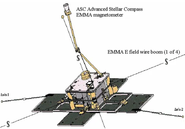
Fig. 1. EMMA sensor locations.
– E − B Correlation and its Scale Size Dependence.
Electric and magnetic fields associated with static struc-tures in the ionosphere are often correlated. The elec-tric field maps, at least partially, upwards along the geo-magnetic field, and the field-aligned current produces a transverse magnetic disturbance field. Assuming com-plete mapping of the electric field the height-integrated ionospheric conductivity may be inferred from the ra-tio of the magnetic to the electric field. At least for large-scale sizes the electric field normally maps well between different altitudes. Studying the degree of cor-relation for smaller scale sizes may yield additional in-formation about the ionosphere-magnetosphere interac-tion processes.
3 Instrument design
EMMA is designed to measure two components of the elec-tric field and three components of the magnetic field simul-taneously with high bit resolution and variable time resolu-tion (see Table 1). The instrument box contains eight printed
circuit boards, holding the electronics for the electric sen-sors, for the fluxgate sensen-sors, for sampling and digitizing of all electric and magnetic sensor signals, for the boom motor control, as well as for the LINDA instrument (Holback et al., 2001). EMMA also has a 12 MB data memory for temporary storage of data either when outside of ground-station contact or when sampling at a data rate exceeding the capacity of the telemetry link.
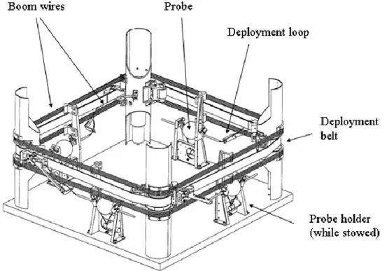
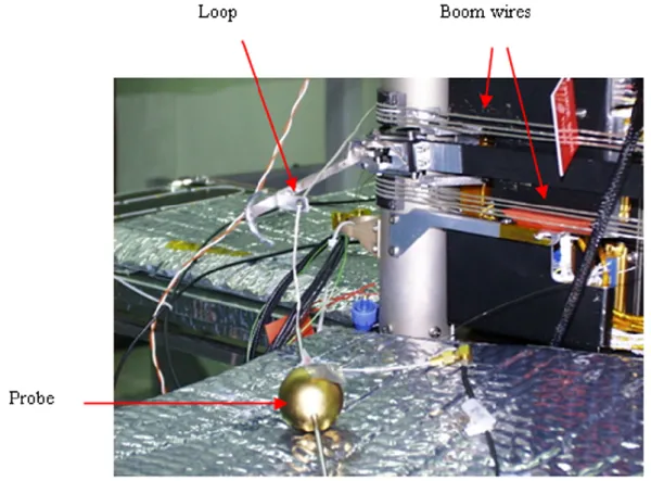
Four spherical sensors located in the spin plane and ex-tended away from the spacecraft using wire booms measure two components of the electric field (see Fig. 1). The deploy-ment system for the wire booms is of a new design where the wire in the stowed configuration is wound around the perime-ter of the spacecraft body. Each wire runs through a small loop, which is attached to a belt driven by a stepper motor. During boom deployment the stepper motor moves the belt up to 2 mm per second. As the belt moves the wires are un-wound from the spacecraft body. In the deployed configura-tion the centre of each probe is located 3.35 m from the centre of the spacecraft. The deployment mechanism is illustrated in Fig. 2.
118 L. G. Blomberg et al.: EMMA – the Electric and Magnetic Monitor of the Aurora on Astrid-2
Fig. 2. EMMA wire boom mechanisms.
The total mass of the boom system including the deploy-ment mechanisms is less than 2 kg, compared to about 14 kg for four conventional mechanisms. For Astrid-2, the booms were fairly short, but there are no fundamental reasons why the new design could not allow for considerably longer boom lengths with only a slight increase in mass. In addition, there are variations of the design that may prove even more vi-able for longer booms. Thus, even though long and low-mass wire booms were not flight tested before the Astrid-2 launch, the successful in-flight performance proved that a significant reduction of the mass of future boom systems is attainable without compromising reliability. Figure 3 shows the boom system in the stowed position. A more detailed description of the low-mass wire boom system is found elsewhere (Hell-man, 1996).
The sensors each have a mass of 100 g, a diameter of 35 mm, and a titanium nitride (TiN) surface. TiN has proved to have excellent surface properties, providing clean electri-cal contact between the probe and the surrounding plasma. This is evidenced, for example, by an almost complete lack of hysteresis in the current-voltage characteristic of the probes. TiN is used also for the LINDA probes on Astrid-2, as well as on the Cassini mission (e.g. Kurth et al., 2001) and is likely, due to its superior properties compared to more traditional coatings such as DAG-213 or vitreous carbon, to become a new standard for probe surface material in space. Figure 4 shows one of the four EMMA probes.
Before sampling, the probe signals are amplified by amplifiers located inside the spacecraft body. Ideally, pre-amplifiers should be mounted as close to the sensor as possi-ble. Often the pre-amplifiers are mounted inside the spherical
sensors, but with the relatively short boom length on Astrid-2 this is not necessary, resulting in a reduction of complex-ity without loss of instrument performance. The signals also pass through low-pass filters designed to suppress aliasing from the sampled signals. The filtering is the same for all (electric and magnetic) sensor signals. The signals from the four electric field probes are sampled individually as volt-ages with respect to the satellite body, and are telemetred individually to the ground. This allows for computational reconstruction of the satellite potential with full time reso-lution, which helps with identifying rapid fluctuations in the plasma density, as well as time intervals, where one or more of the probes are saturated due to spacecraft charging. Each of the four probes can be fed with individually set bias cur-rents, in order to optimize the quiescent point on the current-voltage characteristic, or equivalently, to minimize the con-tact impedance between probe and plasma to make the mea-surement as insensitive as possible to variations in the ambi-ent plasma density or temperature. Low contact impedance provides for as clean as possible a measurement of the probe potential with respect to the plasma. The bias current can be selected either in the range ±40 nA in 20 pA increments or in the range ±450 nA in 220 pA increments. In addition, the bias currents of one or more probes may be stepped through an adjustable sequence of values (known as a current sweep) at an adjustable rate, in order to register the current-voltage characteristics of the probe with respect to the plasma. This is useful for gaining information needed both for optimizing the choice of bias current and for determining plasma and probe properties, such as density, temperature and photoe-mission characteristics.
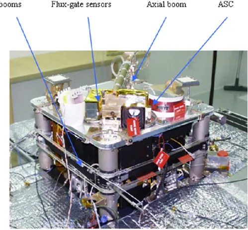
Fig. 3. The Astrid-2 platform.
The fluxgate sensors are located at the end of a 0.9 m long rigid boom extending axially from the platform on the side facing away from the Sun (see Fig. 3). The three sensors are nominally orthogonal to each other, and the sensor unit is co-located with the ASC (Advanced Stellar Compass) cam-era head, in order to optimize the attitude determination of the sensor axes (Jørgensen, 2000; Jørgensen et al., 2003). The fluxgate measurements are based on a principle first de-scribed by Piil-Henriksen et al. (1996), and the sensor design is developed from the one used in the Ørsted mission (Brauer et al., 2000). The raw fluxgate sensor signals are digitally sampled and then three DSPs (Digital Signal Processors) are used to perform the field extraction and the generation of the feedback currents for the sensors, driven by three digital-to-analogue converters (DAC). The excitation frequency is 8 kHz, and the excitation circuit uses parametric amplifica-tion to reduce power consumpamplifica-tion. The algorithms executed by the DSPs form the core of the magnetometer. A more thorough description of the magnetometer is given by Peder-sen et al. (1999). More technical details on EMMA are found in Blomberg et al. (2003).
The ASC was an add-on experiment in an attempt to ob-tain an early test flight of the Ørsted core instruments. It got a number of good star sky pictures, and it provided attitude information for limited periods. Because of the challenges involved in adapting the Ørsted (three-axis stabilized) ASC
to the spinning Astrid-2 platform, an alternative method for attitude determination was developed in parallel at ˚Alborg University, Denmark (Bak, 1999), in part based on the Ørsted attitude control algorithms. The method uses magnetometer data only to build a dynamical model of the spacecraft spin and orientation in space. The method has proved to work well, routinely providing spacecraft attitudes at the 0.1◦ ac-curacy level, compared to the ASC attitudes acquired, as well as based on a statistical analysis. Magnetometer calibrations were performed on an instrument level at the “Magnetsrode” test facility of the Institute of Geophysics and Meteorology, Technical University of Braunschweig, Germany, in the lab-oratory at DTU and at the Danish Meteorological Institute’s Magnetic Observatory at Brorfelde, Denmark (Brauer et al., 2000). The final satellite-level magnetic calibration was per-formed at the Swedish Geological Survey’s Magnetic Obser-vatory at Lov¨o near Stockholm, Sweden. The operating and near-flight configured satellite was exposed to the monitored Earth’s field in about 60 different directions, and a scalar cal-ibration was performed. Taking a local field gradient into account and compensating for the DAC’s non-linearities, the overall standard deviation of the individual data points was 1.3 nTrms. This includes all the perturbations from the
satel-lite and the remaining non-linearities in the sensor and the DACs. At the quasi-DC to 16 Hz filtered output and in a
120 L. G. Blomberg et al.: EMMA – the Electric and Magnetic Monitor of the Aurora on Astrid-2
Fig. 4. The EMMA electric field probe and deployment mechanism.
below 50 pTrms (Pedersen et al., 1999). Tests at Lov¨o
con-firmed the very low magnetic perturbations from the satellite by sequentially power cycling the subsystems. The maxi-mum perturbation came from the transmitter, and it proved to be 4 nT at the boom-deployed magnetometer sensor (Merayo et al., 1998). In flight, when the field changes rapidly over the full scale range, the instrument’s performance was limited by the 1–2 nT ADC-non-linearities. The Earth’s field modelling residuals were less than 5 nTrms, comparing favorably to the
Ørsted modelling residuals of 2–3 nTrms, stemming mainly
from the non-modelled magnetospheric perturbations (Mer-ayo et al., 2002). Technical information on the instrument’s noise and stability performance can be found in this paper and in references therein.
The electric field measurements are more difficult to cali-brate since they are strongly dependent on the local plasma environment. However, for the quasi-static field and for a spacecraft in a low Earth orbit, the dominant component of the measured field is the field induced by the spacecraft mo-tion. The accuracy is, therefore, primarily determined by the accuracy with which this induced field can be subtracted, which, in turn, depends primarily on the accuracy of the atti-tude determination. With an attiatti-tude knowledge of 0.1◦, the induced field is known to be within approximately 0.5 mV/m. The uncertainty added by the electronics is smaller. A pos-sible DC offset in the differential voltage between opposing probes can be calibrated away since the spacecraft is spin-ning. Thus, the quasi-static electric field is normally
accu-rate to well within 1 mV/m. The frequency response of the analogue electronics depends on the plasma impedance. For example, with a plasma impedance of 100 M in parallel with 2.2 pF, the 3 dB cutoff is at 6 kHz. With decreasing plasma impedance the cutoff frequency increases and vice versa. The frequency response is well within 3 dB, up to the maximum sampling frequency of 2048 samples/s for most expected plasma impedances.
The ASC camera was also operating during the magne-tometer calibration, and whenever the star sky was within the camera FOV, the boresight direction and the rotation about the boresight were determined in celestial coordinates. The intercalibration resulted in an angular pointing accuracy of 6 arc s between the output of the magnetometer sensor unit and the local magnetic field (Merayo, 1999; Merayo et al., 1998).
The EMMA data memory consists of 12 MB of RAM for temporary storage of the measured samples and is needed for data recording when the satellite is not in contact with either of the ground stations or when the highest sampling rate is used. The memory is operated as a FIFO, which makes it a transparent telemetry queue that grows, shrinks, or is idle, depending on the sampling rate and on whether the teleme-try stream is switched on or not. Part of the memory is used to hold LINDA data. Depending on the operational mode of LINDA, some fraction of the memory may be allocated as a buffer for LINDA data compression. Also stored in memory are data from the attitude sensors, as well as selected
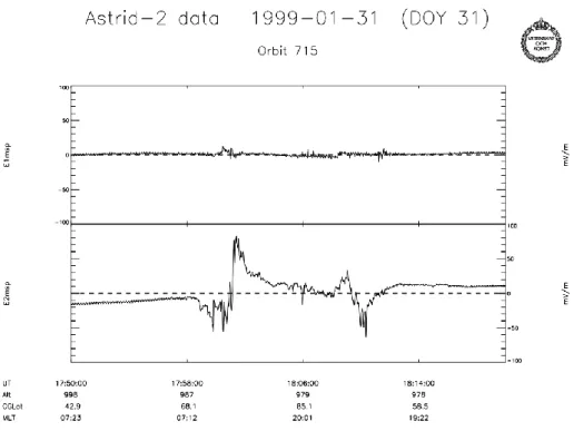
house-Fig. 5. Electric field data from a Northern Hemisphere polar pass showing the normal two-cell convection pattern with a dawn-to-dusk
directed polar cap electric field.
Table 2. Summary of typical EMMA data memory capacity
Sampling rate 16 s−1 256 s−1 2048 s−1 Memory capacity 8 h 30 min 4 min
keeping and status data from EMMA, LINDA, and the ASU (Astrid-2 System Unit).
A typical memory allocation is 8 MB for stored EMMA data, 2 MB for stored LINDA data, and a 2 MB temporary data area for LINDA data used for on-board processing and data compression. Assuming 8 MB for EMMA and that the housekeeping data rate has been set low, approximate num-bers for the time periods for which data can be held in mem-ory are given in Table 2.
4 Operational modes and instrument performance
EMMA can be operated in a variety of different modes. In electric field mode (high-impedance mode), the sensors are biased with a known current (which may be zero, also known as keeping the sensor floating) and their electric potentials with respect to the spacecraft body are measured. By tak-ing the difference in potential between oppostak-ing probes and dividing by their separation distance, the component of the electric field along the line-of-sight between the sensors is obtained. The potentials with respect to the satellite body of the four electric sensors are sampled in synchronism with the three orthogonal flux-gate sensors at either 16, 256, or
2048 samples per second. All four potentials are teleme-tred to ground which makes possible some interferometry, as well as estimation of the satellite potential by taking the aver-age of the potentials of two or more probes. Another mode, mainly used for diagnostics, since it overlaps with the pur-pose of the LINDA instrument, is one where one of the four probes is operated in density mode, biased with a fixed volt-age and the current running to it being measured. Since this is an auxiliary mode, the existing ADC (analogue-to-digital converter) normally used for housekeeping data is used for the current sampling rather than adding extra hardware, and thus, no housekeeping data sampling is performed when the instrument is running one probe in density mode.
Current sweeps may be performed in a highly flexible way. Sweeping is done by stepping either the current or the voltage through a sequence of known values while measur-ing the other quantity. The result of a sweep is a current-voltage characteristic for the probe-plasma coupling, which may provide information on plasma density, plasma temper-ature, photoelectron temperature (if the sensor is sunlit), etc. Parameter tables may be uploaded which govern the current level stepping, and both the duration of the sweeps and their repetition frequency are individually adjustable. The sweep-ing may rotate between the probes or the same probe may be swept at each instance. Since the probe-plasma coupling is capacitive there is a minimum duration per current level for the measurement to make sense. Also, it is desirable that a sweep can be completed within a fraction of a satellite spin. Sweeping is normally not performed at the lowest sampling rate (16 s−1).
122 L. G. Blomberg et al.: EMMA – the Electric and Magnetic Monitor of the Aurora on Astrid-2
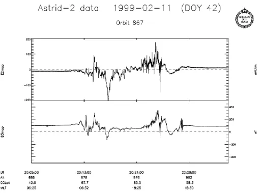
Fig. 6. Electric and magnetic field data from a polar pass through a transpolar auroral arc.
The rate of telemetring housekeeping data can be adjusted in binary steps from 1/4 s upward. Normally, the house-keeping data rate is selected so that the amount telemetred is some reasonably low fraction of the amount of science data. The time needed to dump the data memory to the ground is roughly 14 minutes, assuming there is 10 MB’s worth of stored data and neglecting possible new data stored in mem-ory while dumping. This is close to the length of a long ground station passage.
Figure 5 shows despun electric field data from a polar pass. E1msp and E2msp are both spin plane components. E1msp is along the projection of the magnetic field onto the plane and E2 is perpendicular to B, positive in the duskward direc-tion. The electric field induced by the spacecraft motion has been subtracted, so the plotted components refer to an iner-tial frame of reference. E1msp is seen to be small, which is to be expected for the quasi-parallel electric field at 1000 km altitude. E2msp shows auroral electric fields on either side of the polar cap and a duskward electric across the polar cap, consistent with a normal auroral oval and a two-cell convec-tion pattern.
Figure 6 shows the duskward electric field (E2msp) and the sunward residual (IGRF subtracted) magnetic field (B3msp) for a polar pass through a transpolar auroral arc. Gradients in the sunward magnetic field indicate field-aligned current sheets. The region 1 and region 2 current systems are clearly seen, as well as a current system associ-ated with the transpolar arc. Current densities of the order of a few µA/m2are inferred. Co-located with the arc, and connected to the local current system, we also see sunward plasma convection. These data were obtained during a fairly
unique transpolar arc event lasting at least five hours, dur-ing which Astrid-2 recorded signatures of several different field-aligned currents and associated plasma flow configu-rations in both hemispheres. More details are presented by Blomberg and Cumnock (submitted manuscript, Adv. Space Res., 2002).
5 Summary
EMMA is the electric and magnetic field instrument for the Astrid-2 micro-satellite. It measures two components of the electric field and three components of the magnetic field at sampling rates up to 2048 s−1. Novel technology was
de-veloped in order to fit the instrument into the tight micro-satellite envelope. Most notably, a new wire boom system was flown, significantly reducing the mass compared to con-ventional systems, and the magnetometer was a highly digi-talized flux-gate instrument.
EMMA, as well as other instruments on Astrid-2, have al-ready provided material for several studies of the processes associated with the aurora, as evidenced by a number of pa-pers that have already appeared in the literature, as well as several studies underway.
In conclusion, Astrid-2 and EMMA have demonstrated the feasibility of double-probe electric field measurements on micro-satellites. In addition, lessons on how to make fu-ture micro-satellite missions even more successful have been learned. Ample data for further study exist.
Acknowledgements. Topical Editor T. Pulkkinen thanks two
References
Bak, T.: Spacecraft Attitude Determination - A Magnetometer Approach, Ph.D. Thesis, ˚Alborg University, Denmark, August 1999.
Blomberg, L. G., Lindqvist, P.-A., and Marklund, G. T.: Viking Observations of Electric Fields, in: Proc. of Symp. “Study of the Solar-Terrestrial System,” Killarney, 16–19 June 1992, ESA SP-346, 269, 1992.
Blomberg, L. G., Marklund, G. T., Lindqvist, P.-A., and Bylander, L.: Astrid-2: An Advanced Auroral Microprobe, “Microsatel-lites as Research Tools,” COSPAR Colloquia Series Vol. 10, El-sevier, 1999, 10, 57, 1999.
Blomberg, L. G., Marklund, G. T., Lindqvist, P.-A., Primdahl, F., Brauer, P., Bylander, L., Cumnock, J. A., Eriksson, S., Ivchenko, N., Karlsson, T., Kullen, A., Merayo, J. M. G., Pedersen, E. B., and Petersen, J. R.: The EMMA instrument on the Astrid-2 micro-satellite, TRITA-ALP-Astrid-2003-01, Astrid-2003.
Brauer, P, Risbo, T., Merayo, J. M. G., and Nielsen, O. V.: Flux-gate Sensor for the Vector Magnetometer Onboard the Astrid-2 Satellite, Sensors and Actuators, A Physical, 81, 184, 2000. Eriksson, S., Blomberg, L. G., Ivchenko, N., Karlsson, T., and
Marklund, G. T.: Magnetospheric response to the solar wind as indicated by the cross-polar potential drop and the low-latitude asymmetric disturbance field, Ann. Geophys., 19, 649, 2001. Eriksson, S., Blomberg, L. G., and Weimer, D. R.:
Compar-ing a Spherical Harmonic Model of the Global Electric Field Distribution With Astrid-2 Observations, J. Geophys. Res., 10.1029/2002JA009313, 2002.
Figueiredo, S.: Investigation of Subauroral Electric Fields in the Earth’s Ionosphere Based on Astrid-2 Data, Royal Institute of Technology, Division of Plasma Physics Internal Report, ALP-2001-101, 2001.
Hellman, H.: Design of Wire Boom System for a Satellite, Royal Institute of Technology, Division of Plasma Physics Internal Re-port, ALP-1996-101, 1996.
Holback, B., Jacksen, A., ˚Ahl´en, L., Jansson, S.-E., Eriksson, A. I., Wahlund, J.-E., Carozzi, T., and Bergman, J.: LINDA the Astrid-2 Langmuir probe instrument, Ann. Geophys., 19, 601, 2001.
Høymork, S. H., Yamauchi, M., Ebihara, Y., Narita, Y., Norberg, O., and Winningham, J. D.: Dense ion clouds of 0.1–2 keV ions inside the CPS-region observed by Astrid-2, Ann. Geophys., 19, 621, 2001.
Ivchenko, N. and Marklund, G.: Observation of Alfv´enic activity at 1000 km altitude, Ann. Geophys., 19, 643, 2001.
Ivchenko, N. and Marklund, G.: “Current Singularities” Observed on Astrid-2, Adv. Space Res., 30, 1779, 2002.
Ivchenko, N., Facciolo, L., Lindqvist, P.-A., Kekkonen, P., and Hol-back, B.: Disturbance of plasma environment in the vicinity of the Astrid-2 microsatellite, Ann. Geophys., 19, 655, 2001. Jørgensen, J. L.: In orbit performance of a fully autonomous star
tracker, ESA SP-425, 103, ESTEC, Noordwijk, The Netherlands, 2000.
Jørgensen, J. L., Denver, T., Betto, M., and Van den Braembussche, P.: The PROBA star tracker performance, in: Small satellites for Earth observation, edited by R¨oser, H. P., Sandau, R., and Valenzuela, A., 201, Wissenschaft und Technik Verlag, Berlin, 2003.
Karlsson, T., Marklund, G. T., Blomberg, L. G., and M¨alkki, A.: Subauroral Electric Fields Observed by the Freja Satellite, a Sta-tistical Study, J. Geophys. Res., 103, 4327, 1998.
Keith, W. R., Winningham, J. D., and Norberg, O.: A new, unique signature of true cusp, Ann. Geophys., 19, 611, 2001.
Kurth, W. S., Hospodarsky, G. R., Gurnett, D. A., Kaiser, M. L., Wahlund, J.-E., Roux, A., Canu, P., Zarka, P., and Tokarev, Y.: An overview of observations by the Cassini radio and plasma wave investigation at Earth, J. Geophys. Res., 106, 30 239, 2001. Marklund, G. T., Blomberg, L. G., F¨althammar, C.-G., and Lindqvist, P.-A.: On Intense Diverging Electric Fields Associ-ated With Black Aurora, Geophys. Res. Lett., 21, 1859, 1994. Marklund, G., Karlsson, T., and Clemmons, J.: On Low-Altitude
Particle Acceleration and Intense Electric Fields and their Rela-tionship to Black Aurora, J. Geophys. Res., 102, 17 509, 1997a. Marklund, G., Blomberg, L., Bylander, L., and Lindqvist, P.-A.:
Astrid-2, A Low-Budget Microsatellite Mission for Auroral Re-search, in: Proc. of 13th ESA Symposium on European Rocket and Balloon Programmes and Related Research, ¨Oland, Sweden, 26–29 May 1997, ESA SP-397, 387, 1997b.
Marklund, G. T., Blomberg, L. G., and Persson, S.: Astrid-2, an advanced microsatellite for auroral research, Ann. Geophys., 19, 589, 2001a.
Marklund, G., Karlsson, T., Eglitis, P., and Opgenoorth, H.: Astrid-2 and ground-based observations of the auroral bulge in the mid-dle of the nightside convection throat, Ann. Geophys., 19, 633, 2001b.
Merayo, J. M. G.: Magnetic Gradiometry, Ph.D. Thesis, Institute of Automation, Technical University of Denmark, 1999.
Merayo, J. M. G., Brauer, P., Risbo, T., Pedersen, E. B., Petersen, J. R., and Primdahl, F.: Astrid-2 EMMA Magnetic Calibration, Final Report, Institute of Automation, Technical University of Denmark, Lyngby, Denmark, 1998.
Merayo, J. M. G., Brauer, P., Primdahl, F., Jørgensen, P. S., Risbo, T., and Cain, J.: The spinning Astrid-2 satellite used for model-ing the Earth’s magnetic field, IEEE Trans. Geoscience Electron-ics and Remote Sensing, 40, 898, 2002.
Norberg, O., Winningham, J. D., Lauche, H., Keith, W., Puccio, W., Olsen, J., Lundin, K., and Scherrer, J.: The MEDUSA electron-and ion spectrometer electron-and the ultraviolet PIA photometers on Astrid-2, Ann. Geophys., 19, 593, 2001.
Pedersen, E. B., Primdahl, F., Petersen, J. R., Merayo, J. M. G., Brauer, P., and Nielsen, O. V.: Digital fluxgate magnetometer for the Astrid-2 satellite, Meas. Sci. Technol., 10, N124, 1999. Piil-Henriksen, J., Merayo, J. M. G., Nielsen, O. V., Petersen, H.,
Raagaard Petersen, J,. and Primdahl, F.: Digital detection and feedback fluxgate magnetometer, Meas. Sci. Technol., 7, 1, 1996.