HAL Id: hal-02411073
https://hal.archives-ouvertes.fr/hal-02411073
Submitted on 16 Dec 2019HAL is a multi-disciplinary open access
archive for the deposit and dissemination of sci-entific research documents, whether they are pub-lished or not. The documents may come from teaching and research institutions in France or abroad, or from public or private research centers.
L’archive ouverte pluridisciplinaire HAL, est destinée au dépôt et à la diffusion de documents scientifiques de niveau recherche, publiés ou non, émanant des établissements d’enseignement et de recherche français ou étrangers, des laboratoires publics ou privés.
2D core calculation based on the method of dynamic
homogenization
A. Galia, I. Zmijarevic, R. Sanchez
To cite this version:
A. Galia, I. Zmijarevic, R. Sanchez. 2D core calculation based on the method of dynamic homoge-nization. International Conference on Mathematics and Computational Methods applied to Nuclear Science and Engineering (MandC 2019), Aug 2019, Portland, United States. �hal-02411073�
2D CORE CALCULATION BASED ON
THE METHOD OF DYNAMIC HOMOGENIZATION
Antonio Galia, Igor Zmijarevic and Richard Sanchez∗
DEN-Service d’´etudes des r´eacteurs et de math´ematiques appliqu´ees (SERMA), CEA, Universit´e Paris-Saclay, F-91191, Gif-sur-Yvette, France
[email protected], [email protected], [email protected]
ABSTRACT
Three-dimensional deterministic core calculations are typically based on the two-step ap-proach, where the homogenized cross-sections of an assembly type are pre-calculated for different physical parameters using the critical-leakage model, and then interpolated to the actual state in the reactor. On the other hand, direct transport calculations, mostly based on the method of characteristics, have recently been applied, showing a prohibitive computational time for routine design purposes, due to the current machine capabilities. Because of this, a simplified transport solution, the so called 2D/1D Fusion method, has been developed achieving very precise results but still remaining expensive in the context of multiphysics and core depletion calculations. In the present work, we propose a method of Dynamic Homogenization (DH) as an alternative technique for three-dimensional core calculations which can lie between the two approaches, the classical and the direct one, in terms of precision and performance. The aim of the present work is to present pre-liminary analysis and tests of the DH technique for two-dimensional configurations. The NEA ”PWR MOX/UO2 Core Transient” Benchmark was chosen to perform the calcula-tions and compare the different approaches.
KEYWORDS: Core Calculations, Dynamic Homogenization, Domain Decomposition, PWR, APOLLO3 R
1. INTRODUCTION
The two-step calculation scheme has been widely used for core modeling and design thanks to its effectiveness in obtaining fast results at different core configurations. The first step of this approach consists of ”off-line” 2D calculations for each assembly type, that are typically performed with the method of characteristics (MOC) on fine spatial and energy mesh with high order angular dependency, to produce a library of homogenized cross-section that are calculated for different physical parameters, such as burnup, moderator density, fuel temperature, etc. At this stage, the surrounding environment of the assembly is not known, so conservative conditions are imposed at the boundaries, as if the motif was repeated to infinity (the so called infinite lattice calculation). However, it is possible to adjust the spectrum of condensation by introducing the critical-leakage model, whereupon the neutron flux is written as the product of a macroscopic distribution in space,
∗
the solution of the Laplace equation, Eq. (1), and a periodic fundamental flux, that is the transport solution within the motif.
∇2φ(r) + B2φ(r) = 0 (1)
The real number B2 of Eq. (1) is the buckling of the macroscopic distribution φ(r), and it is searched iteratively in such a way that the keff of the assembly is equal to one. The so called
”critical” buckling is then used in the Bn equations to find the fundamental spectrum and then
compute the leakage rate for each energy group, which is typically assumed homogeneous in space. The flux resulting from the heterogeneous transport equation with imposed homogeneous leakage, is finally used to homogenize cross-sections. Nevertheless, for reflector homogenization a different approach has to be used, since no multiplication occurs and vacuum conditions are imposed on at least one boundary. In litterature there is a large number of procedures that have been adopted, like 1D models, 2D calculations with one fuel assembly next to a reflector ”assembly”, or one row of 8 or 9 fuel assemblies next to each others including the reflector at the end, or even bigger motifs of 5x5 assemblies containing a reflector layer surrounding the core. Once the cross-sections have been homogenized in space and condensed in energy, an equivalence technique between the fine-transport and the low-order operators is applied. One of the most common techniques is the SuPerHomogenization (SPH) proposed by Kavenoky [1] and later refined by H´ebert [2], that modifies the homogenized cross-section so as to preserve the reference reaction rates and, therefore, the reference total leakage for each coarse zone of homogenization. Another widely used technique is the homogenization via Flux Discontinuity Factors (FDF) analysed by Koebke [3,4], Smith [5] and Sanchez [6]. In this case the reference net currents are preserved at each side of the coarse zone and, consequently, the reference reactions rates in it. It has been shown that using equivalence parameters improves significatively the quality of the solution of the two-group diffusion core calculation [5,7], and typical pin power errors found in litterature are reduced from around 10-12% to roughly 5-7% with respect to a reference calculation of a typical LWR at nominal conditions.
One of the main source of these errors is due to the fact that no enviroment is considered at the homogenization stage. The assemblies that are the most sensitive to this approximation are those at the peripheral area next to the reflector and those next to other types of assembly such as the UOx-MOx or Rodded-Unrodded intefaces. Another source of error might arise because the coarse discretization of the core operator is inadequate to describe the physics of the problem. For in-stance, in 2011 Grundmann and Mittag [8] have computed the NEA PWR UO2/MOX Benchmark [9] using the code DYN3D with a simplified P3 operator, 8 energy groups, with and without SPH
equivalence, showing better results with respect to nodal two-group diffusion models adopted by the benchmark participants, halving the standard deviation of the assembly power relative error, with a peak of pin power error of around 7-8%.
On the other hand, many attempts were made in the past to take into account the information of the environment at the homogenization stage. They can be divided into three families: the straightforward approach, the cross-section correction approach, and the iterative core-assembly technique. The straightforward approach consists of running colorset calculations, combining each type of assembly in the core, to homogenize with a realistic environment. This approach can be expensive, especially if one has to consider all the possible combinations of assembly types. The second approach is to approximate the environment effect by correcting the homogenized nuclear data. Rahnema et al [10,11], used a linear perturbative method to recalculate the homogenized cross-sections at different current-to-flux ratio boundary conditions, where the latter is computed
at the core calculation, and the perturbative coefficients with the help of several off-line assembly calculations, so that in the iterative process of cross-section correction, no lattice calculation need to be performed. With a similar philosophy of off-line cross-section generation, Clarno et al. [12] used energy, angle, and space dependent albedos to simulate the presence of the neighbors of different type. Another approach adopted by Palmtag for UOx-MOx interfaces [13] consists of using only core quantities, such as the leakage and the spectral index of an assembly, to estimate the correction. More recently, a modern calculation scheme belonging to the third family was explored by Takeda et al. [14]. It consists of an iterative process between core and lattice calculation, where the core macro currents are used to compute the albedo boundary conditions that are imposed at the assembly level in the next iteration. This approach is computationally more expensive but it does not require any off-line branch calculation. However, each lattice calculation is independent of the others because it only depends on core quantities, which entails that the spectrum of the neighbor assemblies cannot be properly taken into account.
The method that we propose takes the exact fine distribution in energy, space and angle from the neighboring assembly, which is then normalized by the partial core macro-current, so as to pre-serve assembly exchanges. Each assembly has then different boundary conditions that account for its position in the core and for the isotopic content of the neighboring assemblies: both sources of gradients in a reactor. The calculations are then more expensive but the results are expected to have a better quality than the classical approach. The method was proposed by P. Mondot and R. Sanchez in 2003 [15] and tested for simple cases in 1D problems. In 2014, D. Colameco et al. ex-tended the application to 2D configurations, introducing in the iterative process an equivalence by discontinuity factors [16]. They obtained good agreement against reference transport calculation for a 2x2 cluster of UOx and MOx assemblies with reflection boundary conditions. The method was also adopted for Pebble Bed Reactors by M. Grimod et al. in 2015 [17], with a further approx-imation on the interface exchange: an isotropic angular flux to avoid angular dependencies. In this work, the method is described in detail and tested in a PWR core configuration with different types of assemblies and burnup. Finally, a comparison with direct transport (considered as reference) and the classical two-step approach is shown.
2. DYNAMIC HOMOGENIZATION APPROACH
The Dynamic Homogenization is an iterative process between assembly and core calculations. In the context of the Domain Decomposition Method (DDM) and for 2D configurations, it can be seen as a mirror image of a coarse nonlinear acceleration of a transport calculation. Let D be the global geometrical domain, Γ = ∂D its boundary and ND the number of subdomains, which
comprise fuel and reflector ”assemblies”. The global core transport problem becomes then a set of coupled sub-problems (Eq. (2)) that can be solved in parallel by iterating on the fluxes entering (ψin,i) and exiting (ψout,j) the subdomains at their interfaces with neighbors:
Liψi = Hiψi+ 1λFiψi, r ∈ Di, ψin,i= ψout,j, rs∈ Γij = Γi∩ Γj, ψi = βiψi+ ψin,i, rs∈ Γi∩ Γ, (2) where D = S
i=1,NDDi is the partition of the core into i = 1, ND assemblies, Di and Γi are,
respectively, the domain and the boundary of assembly i and Γij = ΓiT Γjis the interface between
scattering and fission production. Each assembly calculation is solved with imposed multiplication constant λ, and fixed incoming boundary sources ψin,i. The first one, being an integral parameter
of the whole domain, is determined at the core level using Eq. (3):
λn+1C = λnChw, FCΦ
n+1i
hw, FCΦni
, (3)
where C stands for coarse, F for production operator, Φ for scalar flux, w for a weight function and n for the n-th outer coarse core iteration.
Transport calculations via DDM may have a slow convergence since a third iteration loop arises, so the Spatial Domain Decomposed Coarse Mesh Finite Differences (SDD-CMFD) method is typ-ically used as coarse operator for its effectiveness in accelerating non-linear direct MOC transport methods [18,19] and 2D/1D Fusion methods [20]. THE SDD-CMFD is a finite differences diffu-sion solver with corrected diffudiffu-sion coefficient to preserve transport currents.
At each iteration of the outermost loop, the transport fluxes on the fine mesh are rescaled to the coarse scalar flux using Eq. (4):
ψr,h,gn+1 = ψr,h,gn+1/2 Φ n+1 R,G P g∈G P r∈Rφ n+1/2 r,g , (4)
where r,h,g are respectively the fine region, the angular moment and the energy group index and, R and G are the coarse region and coarse energy group of the CMFD solver, n is the iteration index, φ the transport scalar flux, Φ the coarse scalar flux and ψ the angular transport flux. This is the classical acceleration equation for CMFD, but in the context of spatial domain decomposition, the outgoing anguar fluxes of a subdomain are also accelerated with a rescaling factor. This factor has been calculated in different ways, such as the ratio of coarse-to-transport scalar fluxes [21] (P0
approximation), or as the ratio of coarse-to-transport partial currents [22] (DP0approximation), or
using a P1 approximation [23] that allows to update the flux with a different ratio per direction.
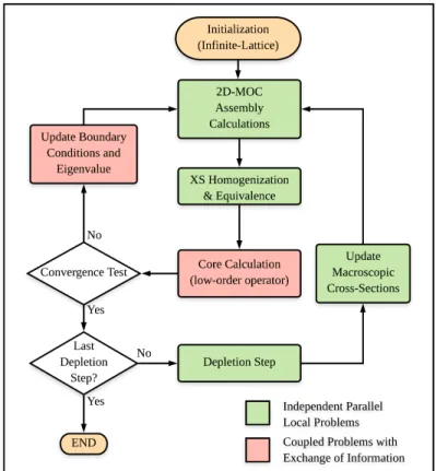
The second equation of the problem in Eq. (2) corresponds to the angular flux continuity condition that has to be imposed by a method of domain decomposition for the local transport solution. In the DH approach instead, even if the iterative calculation scheme is quite similar to a direct transport calculation (Fig. 1), the angular fluxes are not continuous at the boundaries and the discontinuity is introduced by the ratio of coarse-to-transport partial currents. The incoming angular flux ψin,
in fact, is equal to the product of the flux ψout leaving the neighboring assemblies at the previous
iteration, which gives the fine distribution in space, energy and angle, and a current normalization factor as in Eq. (5): ψing (r, Ω) |n+1Γ ij = ψ g out(r, Ω) |nΓij × JG in(~r) |ncore P g∈G R | n · Ω | ψgout(r, Ω)dΩ |n Γij ∀g ∈ G, (5)
where n denotes the outer transport iterations on the interface currents, n the unit vector normal to the interface and g and G the fine (transport) and coarse group. Note that the incoming fluxes are normalized so as to preserve the macroscopic coarse currents Jin entering the assemblies and that
the current normalization factor is not equal to one at the convergence of the iterative process. Because of this boundary approximation, the transport solution in DH does not correspond to the exact direct transport solution, since the former depends on the low-order operator. The coarse currents depend only on the homogenized cross-sections per macro-group and macro-region, and
have a faster convergence than the fine transport angular interface fluxes. Introducing the discon-tinuities at the interfaces eases the constraints of the transport problem and allows to preserve the eigenvalue from the low-order operator. Entailing that one might use rough angular fluxes at the interfaces between assemblies. The convergence test of Fig. 1 checks the following quantities and criteria at two successive global iterations n:
• Eigenvalue λC: |λnC − λn+1C | < 10 −5;
• Fission Integral Frper transport region r: max(|1 − Fn
r
Frn+1|) < 10
−4;
• Incoming Flux ψs,d,g− per boundary surface s, direction d and group g: k1 − ψ
−,n s,d,g
ψs,d,g−,n+1k2 < 10 −4.
Moreover, another difference with respect to the direct scheme is that the fission source iteration loop is computed and accelerated locally at the assembly level. Nonetheless, the 3D configurations will be analysed in future work, and the similitudes with direct transport via DDM will vanish, since the assembly calculations are still performed in 2D transport using an approximation to take into account the axial leakage. Note that only static calculations are considered in this work and depletion calculation in the external loop of Fig. 1 is not studied.
Figure 1: Dynamic Homogenization calculation scheme.
3. APPLICATION AND COMPARISON
The problem that we have analyzed was inspired by the NEA PWR MOX/UO2 Core Transient Benchmark [9], adopting some simplifications in order to have smaller data library to process for
preliminary calculations. We have considered only two types of assemblies instead of four, the UOx with 4.5% enrichment and the MOx with an average content of Pu-fissile of 4.3%. Both assemblies have been irradiated at infinite-lattice conditions to obtain the necessary macroscopic cross-sections at three burnup states: fresh fuel at 0 GWd/t, once-burned at 20 GWd/t and twice-burned at 35 GWd/t. The core layout is shown in Fig. 2. The UOx assembly contains guide tubes, fuel pins with and without IFBA (Integral Fuel Burnable Absorber). The MOx assembly contains guide tubes with and without WABA pins (Wet Annular Burnable Absorber), and a three-zone MOx fuel with 5.0%, 3.0% and 2.5% fissile Pu (in respectively the interior, periphery and corner positions). Hot Zero Power conditions have been considered to evaluate nuclear data.
Figure 2: Core layout of NEA Benchmark [9].
It contains two types of assembly (UOx, MOx) and three burnup (0, 20, and 35 GWd/t).
Three cases are compared: reference transport (DIRECT), Two-Step, and DH approach. The direct transport calculation has been performed using the IDT standalone solver of the code APOLLO3 R
developed at CEA, which is a multigroup discrete ordinates short characteristics solver. The source iterations are carried out by cell sweeping, where the Coarse Mesh Finite Differences method (CMFD) is used as acceleration for the outer iterations and the Boundary Projection Acceleration (BPA) for the inners [24–26]. A parabolic Nodal Expansion Method (order 2) for diffusion (NEM) [7] has been used for the coarse core calculation in the two-step scheme and in the DH approach, in order to compare the results using the same coarse operator. The reference calculation was per-formed in 172 energy groups with transport corrected P0 scattering. The pin-wise homogenization
from 172 to 2 groups is done using a volume-flux weighting function according to Eq. (6). x stand for reaction type, r and R respectively for fine transport and coarse region, g and G respectively for the transport and the coarse energy group, V the volume and Φ the scalar flux. The SPH equiva-lence is applied to the two-step and DH calculation using Eq. (7), where τ is the reference reaction rate to be preserved, C stands for coarse and n is the iteration index. The convergence of fixed point iterations in the DH approach requires in average 5 to 10 more iterations than the classical one because of the open boundary conditions, but we have checked that the method converged for all fuel assemblies.
Σhx,R,G= τx,R,G VRΦ¯R,G = P r∈R P g∈GΣx,r,gVrΦr,g P r∈R P g∈GVrΦr,g , (6)
Σeq,n+1x,R,G = τx,R,G VRΦC,nR,G
. (7)
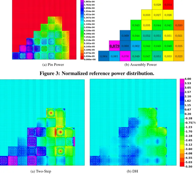
However, the reflector cross-sections are homogenized by the two approaches in two different ways. For the two-step scheme, we have run a separate calculation of a 9x1 cluster of assemblies, where the last assembly contains the reflector and is homogenized into two media (one for the iron and one for the water) that were used at the second step for the whole reflector surrounding the core. The equivalence was then applied and it was verified that it converged. In the DH approach, there is no need to run separate calculations, since the environment is known, and the reflector cross-sections were homogenized into a 17x17 grid geometry, with the same mesh size of a fuel assembly. In this case, we have observed that the equivalence was not converging, probably due to the increase in the number of degrees of freedom. Both direct and DH calculation were performed in a parallel environment for space domain decomposition with MPI libraries and 40 processors for 40 subdomains. The reference power per pin and per assembly is represented in Fig. 3 after normalization such that the power of one eighth of the core is equal to one. The distribution of relative errors calculated using Eq. (8) is shown for the two approaches in Fig. 4 and Fig. 5. The errors extrema and root mean square (Eq. (8)) are shown in Table 1.
ei = Pi − Pi ref Pi ref , RMS = s PNpins i e2i Npins . (8)
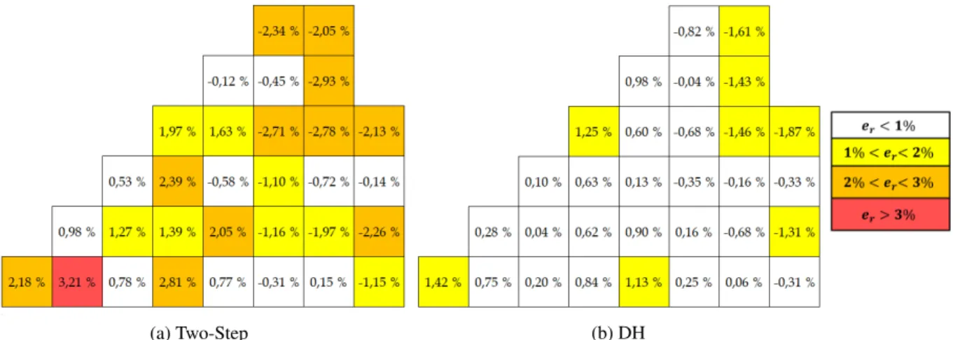
In the two-step scheme the errors at the interface with the reflector can be higher if not well mod-eled and the error peak is found at the interface with a MOx assembly. This is caused by the fact that at the reflector homogenization stage, the assembly next to the reflector contained UOx fuel, which has a different spectrum. Also, an increase of the errors was seen not only at the UOx-MOx interfaces, but also for the UOx-UOx with different burnup. In particular, fresh UOx assemblies containing IFBA present are sensitive to the environment information. As expected, in the DH approach the error peaks introduced by the infinite lattice approximation were eliminated, and an improved solution in the assemblies close to the reflector was found. However, this region of the reactor is still the most difficult to treat, since it strongly depends on the reflector properties that might not be well modeled by 2-group diffusion. In Table 2, calculation run-times and number of iterations are presented. The MOSC operator has been accelerated by SDD-CMFD with different energy meshes of condensation (2, 6, 26 and 172 groups). The first two energy meshes gave the lowest run-time, so the other two are not compared with DH. The gain of run-time in DH over the direct approach is mainly due to the lesser number of global iterations (10 instead of 16), and secondly by the computational cost of the coarse operator. We have observed that the nodal so-lution after 5 iterations does not change significantly, which means that cross-sections are closed to the converged values, but the process needs 5 more iterations to converge the transport quanti-ties. On the other hand, SDD-CMFD requires more iterations per global one, because even if the homogenized cross-sections do not change very much, the matrix coefficients depend also on the homogenized partial currents and surface fluxes per coarse region.
4. CONCLUSIONS
In this work we have applied an innovative homogenization method for a core calculation that pre-serves assembly exchanges. Preliminary calculations show results of better quality with respect to the classical two-step approach, eliminating the typical error peaks at the interface between differ-ent assembly types and improving the reflector response, where typically two-step fails. Besides
Method keff k−kref max(ei) min(ei) RMS
Two-Step 0,97201 -51 pcm 6,4% -5.8% 1,14% DH 0,97221 -31 pcm 3,2% -3,6% 0,57% Table 1: Comparison of Two-Step and DH methods against reference.
Method N. global iterations Run-Time DIRECT-CMFD2g 16 22,3 min DIRECT-CMFD6g 16 23,6 min
DH 10 9,3 min
Table 2: Comparison of run-time calculation (40 parallel process).
(a) Pin Power (b) Assembly Power
Figure 3: Normalized reference power distribution.
(a) Two-Step (b) DH
(a) Two-Step (b) DH
Figure 5: Assembly Power Relative Errors in case of Two-Step and DH methods. avoiding the infinite lattice approximation and leakage model, the DH approach has several advan-tages such as follow: (i) no need for a flux reconstruction, since the transport solution is locally available; (ii) no need for a multiparametrized cross-sections library and, therefore, no need for in-terpolation of homogenized data, since the assembly transport calculation can be performed at the actual core conditions. Moreover, (iii) the depletion calculation can be performed using transport fluxes at the pin-level and imposing the assembly power density from the actual power distribu-tion. Another advantage of the method is (iv) the possibility to homogenize the reflector using a heterogeneous geometry and taking into account the real environment of the core. The DH method exhibts a higher convergence rate with respect to a direct calculation for 2D configurations, halving the wall-clock time. This is promising for 3D core calculations via DH where no 3D transport is performed.
REFERENCES
[1] A. Kavenoky. “The SPH homogenization method.” Procedings of a Specialists’ Meeting on Homogenization Methods in Reactor Physics(1978).
[2] A. H´ebert. “A Consistent Technique for the Pin-by-Pin Homogenization of a Pressurized Water Reactor Assembly.” Nucl Sci Eng, volume 113(3), pp. 227–238 (1993).
[3] K. Koebke. “A New Approach to Homogenization and Group Condensation.” IAEA-TECDOC, (231), p. 303 (1980).
[4] K. Koebke and L. Hetzelt. “On the Reconstruction of Local Homogeneous Neutron Flux and Current Distributions of Light Water Reactors from Nodal Schemes.” NNucl Sci Eng, volume 91, pp. 123–131 (1985).
[5] K. Smith. “Assembly homogenization techniques for light water reactor analysis.” Progress in Nuclear Energy, volume 17(3), pp. 303 – 335 (1986).
[6] R. Sanchez. “Assembly homogenization techniques for core calculations.” Progress in Nu-clear Energy, volume 51(1), pp. 14 – 31 (2009).
[7] R. Sanchez, G. Dante, and I. Zmijarevic. “Diffusion Piecewise Homogenization via Flux Discontinuity Ratios.” Nucl Eng Technol, volume 45(6), pp. 707 – 720 (2013).
[8] U. Grundmann and S. Mittag. “Super-homogenisation factors in pinwise calculations by the reactor dynamics code DYN3D.” Ann Nucl Energy, volume 38(10), pp. 2111 – 2119 (2011).
[9] T. Kozlowski and T. J. Downar. “PWR MOX/UO2 Core Transient Benchmark (Final Re-port).” NEA/NSC/DOC(2006)20, volume 6048 (2007).
[10] F. Rahnema and E. M. Nichita. “Leakage corrected spatial (assembly) homogenization tech-nique.” Ann Nucl Energy, volume 24(6), pp. 477 – 488 (1997).
[11] Rahnema, Farzad, Mckinley, and Michael. “High-order cross-section homogenization method.” Ann Nucl Energy, volume 29, pp. 875–899 (2002).
[12] K. T. Clarno and M. L. Adams. “Capturing the Effects of Unlike Neighbors in Single-Assembly Calculations.” Nucl Sci Eng, volume 149(2), pp. 182–196 (2005).
[13] S. Palmtag and K. Smith. “Two-group spectral corrections for MOX calculations.” Proc of the Int Conf on the Physics of Nuclear Science and Technology, volume 1 (1998).
[14] T. Takeda and K. K. Y. Fujita. “Leakage Dependent SPH Factor for PWR Whole Core Trans-port Calculation.” Int Conf of the Physics of Reactors Nuclear Power: A Sustainable Re-source(September 2008).
[15] P. Mondot and R. Sanchez. “An iterative homogenization technique that preserves assem-bly core exchanges.” International conference on supercomputing in nuclear applications SNA’2003(2003).
[16] D. Colameco, B. Ivano, D. Beacon, and K. Ivano. “Iterative Transport-Diffusion Methodol-ogy for LWR Core Analysis.” SNA+MC 2013, volume 41 (2014).
[17] M. Grimod, R. Sanchez, and F. Damian. “A dynamic homogenization model for pebble bed reactors.” Nuclear Science and Technology, volume 52, pp. 932 – 944 (2015).
[18] K. Smith and J. Rhodes. “Full Core, 2-D, LWR Core Calculations with CASMO-4E.” Pro-ceedings of PHYSOR 2002(October 2002).
[19] B. Kelley and E. Larsen. “CMFD acceleration of spatial domain-decomposed neutron trans-port problems.” International Conference on the Physics of Reactors 2012, PHYSOR 2012: Advances in Reactor Physics, volume 1, pp. 715–727 (2012).
[20] Y. S. Jung, C. B. Shim, C. H. Lim, and H. G. Joo. “Practical numerical reactor employing direct whole core neutron transport and subchannel thermal/hydraulic solvers.” Ann Nucl Energy, volume 62, pp. 357 – 374 (2013).
[21] R. Lenain, E. Masiello, F. Damian, and R. Sanchez. “Coarse-Grained Parallelism For Full-Core Transport Calculations.” PHYSOR 2014: The Role of Reactos Physics toward a Sun-stainable Future(2014).
[22] S. Stimpson, B. Collins, B. Kochunas, and T. Downar. “Boundary Acceleration Techniques for CMFD-Accelerated 2D-MOC.” PHYSOR 2014: The Role of Reactos Physics toward a Sunstainable Future(2014).
[23] B. Kochunas, B. Kelley, S. Stimpson, E. Larsen, and T. Downar. “Application of the SDD-CMFD Acceleration Method to Parallel 3-D MOC Transport.” PHYSOR 2014: The Role of Reactos Physics toward a Sunstainable Future(2014).
[24] R. Sanchez, I. Zmijarevic, and M. Coste-Delclaux. “APOLLO2 Year 2010.” Nucl Eng Tech-nol, volume 42(5) (October 2010).
[25] E. Masiello, R. Sanchez, and I. Zmijarevic. “New Numerical Solution with the Method of Short Characteristics for 2-D Heterogeneous Cartesian Cells in the APOLLO2 Code: Numer-ical Analysis and Tests.” Nucl Sci Eng, volume 161(3), pp. 257–278 (2009).
[26] Y. S. Ban, E. Masiello, R. Lenain, H. G. Joo, and R. Sanchez. “Code-to-code comparisons on spatial solution capabilities and performances between nTRACER and the standalone IDT solver of APOLLO3 .” Ann Nucl Energy, volume 115, pp. 573 – 594 (2018).R
![Figure 2: Core layout of NEA Benchmark [9].](https://thumb-eu.123doks.com/thumbv2/123doknet/12988246.378980/7.918.286.624.285.546/figure-core-layout-of-nea-benchmark.webp)