HAL Id: hal-02485129
https://hal.archives-ouvertes.fr/hal-02485129
Submitted on 19 Feb 2020HAL is a multi-disciplinary open access archive for the deposit and dissemination of sci-entific research documents, whether they are pub-lished or not. The documents may come from teaching and research institutions in France or
L’archive ouverte pluridisciplinaire HAL, est destinée au dépôt et à la diffusion de documents scientifiques de niveau recherche, publiés ou non, émanant des établissements d’enseignement et de recherche français ou étrangers, des laboratoires
using Metal Hydrides
Maxime Botzung, Serge Chaudourne, Christian Perret, Michel Latroche,
Annick Percheron-Guegan, Philippe Marty
To cite this version:
Maxime Botzung, Serge Chaudourne, Christian Perret, Michel Latroche, Annick Percheron-Guegan, et al.. Development and Simulation of a Hydrogen Storage unit using Metal Hydrides. 18e Congrès Français de Mécanique, Aug 2007, Grenoble, France. �hal-02485129�
Development and Simulation of a Hydrogen Storage unit using Metal
Hydrides
BOTZUNG Maximea, CHAUDOURNE Sergea, PERRET Christiana, LATROCHE Michelb, PERCHERON-GUEGAN Annickb, MARTY Philippec.
a
Affiliation: CEA Grenoble, DRT/ LITEN/ DTH, 17 rue des Martyrs 38054 Grenoble, [email protected]
b
Affiliation: CNRS, CMTR-ICMPE-UMR7182, 2 - 8 rue Henri Dunant 94320 Thiais Cedex, [email protected]
c
Affiliation: CEA, Equipe LEGI-GRETh, 17 rue des Martyrs, 38054 Grenoble Cedex, [email protected]
Abtract :
This paper presents a hydrogen storage system using metal hydrides for a Combined Heat and Power (CHP) system. Hydride storage technology has been chosen due to project specifications: high volumetric capacity, low pressures (< 3.5 bar) and low temperatures (< 75°C: fuel cell temperature).
During absorption, heat from hydride generation is dissipated by fluid circulation. An integrated plate-fin type heat exchanger has been designed to obtain good compacity and to reach high absorption/desorption rates. At first, the storage system has been tested in accordance with project specifications (absorption/desorption 3.5/1.5 bar). Then, the hydrogen charge/discharge times have been decreased to reach system limits.
System design has been used to simulate thermal and mass comportment of the storage tank. The model is based on the software Fluent. We take in consideration heat and mass transfers in the porous media and a convective flow for cooling/heating the system during absorption/desorption. The hydride thermal and mass behaviour has been integrated in the software.
The heat and mass transfers experimentally obtained have been compared to results calculated by the model.
Résumé :
Dans cet article est présenté un stockage d’hydrogène sur Hydrures métalliques intégré à un système de cogénération.
Le choix du stockage d’hydrogène s’est orienté vers les hydrures afin d’obtenir une bonne capacité volumique avec des pressions faibles (< 3.5 bar) et des températures adaptées aux piles à combustibles (< 75°C).
Pendant l’absorption, l’hydrure métallique dégage de la chaleur qui est dissipée par une circulation de fluide. Un échangeur à plaques et ailettes permet d’obtenir une bonne compacité avec des temps de chargement/déchargement rapides. Le système a été testé à débit constant puis à pressions constantes (absorption/désorption 3.5/1.5 bars).
Les géométries ont été maillées afin de simuler les transferts thermiques et massiques. On prend donc en compte un écoulement convectif couplé à une disparition massique et un apport de chaleur dans un milieu poreux. Cette simulation est basée sur le logiciel Fluent auquel est couplé le comportement de l’hydrure métallique. Les valeurs expérimentales obtenues ont ensuite été comparées aux valeurs résultant du modèle.
1 Introduction
Hydrogen storage represents a technological challenge to be solved for a commercial development of energy converters using hydrogen. Among the different hydrogen storage means (compressed gas, liquid hydrogen, adsorption and absorption in solids) reversible metal hydrides are considered as a safe and volume efficient hydrogen storage medium, offering low pressure and high energy density. In the present work, a metal hydride buffer tank will be used in connection with a hydrogen production unit to supply a 40 kW stationary proton exchange membrane fuel cell. The production unit will provide hydrogen gas at a pressure of 3.5 bar while the fuel cell is supplied with gas at 1.5 bar. In between, the storage tank will be used as a buffer working at an average temperature of 75 °C. For this study, LaNi5 substituted derivatives
(AB5-type compounds) were chosen as hydrogen storage materials to reach the needs of the
specific application.
The aim of this study is to test a Metal Hydride tank based on plate fin technology. The results of theses tests will help building a tool able to simulate the behaviour of the Metal Hydride tank.
2 Presentation
The design of the CHP system requires 5 kg hydrogen storage but in a first step, only a 0.1 kg prototype has been built and tested. According to the weight capacity of the alloy, the tank should contain 10 kg of hydride.
The Metal Hydride tank must fulfill the following conditions: ¾ Storage of 1.12 Nm³ H2 (100 g) in 10 kg of Metal Hydride.
¾ Absorption in 15h with 3.5 bars (Flow rate H2: 75 NL/h) at 75°C.
¾ Desorption in 9h with 1.5 bars (Flow rate H2: 125 NL/h) at 75°C.
The study of AB5: Iosub (2006) compounds led to the development of a composition adapted to
the project needs. The hydride composition is
La
0.90Ce
0.05Nd
0.04Pr
0.01Ni
4.63Sn
0.32 . The absorption and desorption pressures of the hydride at 75 °C (2 and 1.85 bar respectively) are the most adapted to the specifications. The reversible storage capacity (0.95 %wt) has been optimized to our work conditions and chemical kinetics is fast.3 Design of the Metal Hydride tank (MH tank)
To decrease the hydrogen charging/discharging time, the heat exchange capability has to be improved. A rectangular design has been chosen to obtain a good compacity with an integrated plate fin type heat exchanger which is an efficient heat exchanger.
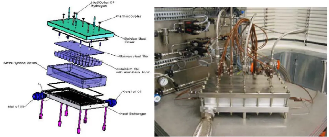
The various components of the plate fin type MH tank are shown in Figure 1. The metallic powder is filled into the Metal Hydride Vessel with Aluminium Fins and Aluminium Foam to improve the heat transfer. The heat exchanger and the MH vessel have been made with aluminium according to its high thermal conductivity. The coolant flows from Inlet of Oil to Outlet of Oil through 12 square pipes in the Heat Exchanger.
A Stainless steel filter has been introduced in the MH tank. This filter avoids MH transfer into hydrogen pipes (Inlet/Outlet of Hydrogen) and prevents the powder from escaping from the tank. The MH tank can be moved and can be subjected to vibrations (inside a car). In addition, the pressure drop of hydrogen within the MH powder layer is reduced because the MH layer is small. The Stainless Steel cover contains 6 groups of 3 thermocouples to measure the temperature at various levels inside the Metal Hydride bed (MH bed).
Fig 1- Expanded view (left) of the Metal Hydride tank (right).
The heat transfer characteristics in the Metal Hydride are measured by using thermocouples. Several thermocouples (TC) have been introduced in the Metal Hydride vessel at different heights (Figure 2).
3 thermocouples at various heights inside
the MH bed
Aluminium Foam & Metal hydride (MH bed)
Fig 2- Repartition of the three thermocouples at different levels inside the MH bed.
Another effect to be taken into account is the powder volume expansion during hydrogen absorption . In fact, when hydrogen reacts with the alloy, it occupies cristallographic sites within the cell leading to an expansion of of the metallic matrix.
Accordingly, the metallic powder can expand 12% of its initial volume. If the expansion effect is not taken into account, it may generate stress which can cause damages on the MH tank. In order to limit the stress in the tank, a void space has been designed. This void space represents 20% of the total metal powder volume.
The filling of the MH vessel with the Metal Hydride powder has been done inside , a glove box under argon in order to avoid contamination of the powder by oxides or water.
This system has been designed to identify the thermal behaviour of the Metal Hydride Storages systems. The aim is to use the heat from the fuel cell to desorb hydrogen and the test bench can simulate the fuel cell behaviour.
4 Results
4.1 Constant Flow rate
Thereafter, absorption/desorption characteristics of the metal hydride tank will be given and the heat and mass transfers in the storage vessel will be presented.
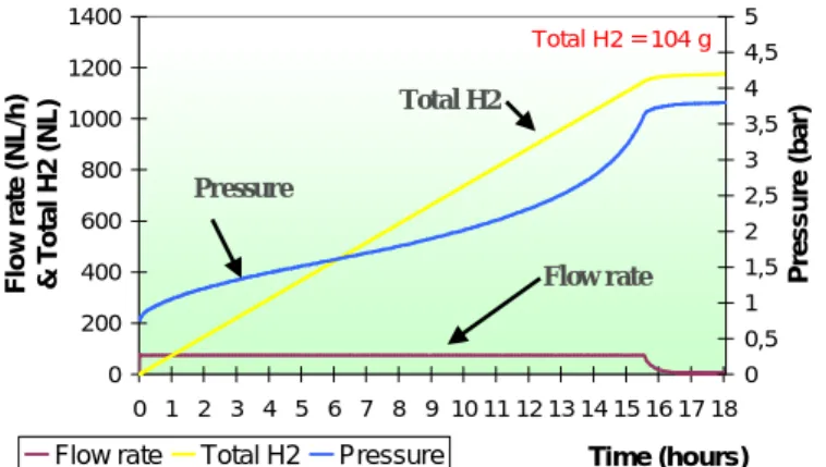
In Figure 3, the absorption curve for a full charge is shown. The H2 flow rate is imposed at 125
NL/h. During absorption, the pressure increases from the equilibrium pressure (0.7 bar at 65°C) up to the set point pressure (3.5 bar). The Total H2 uptake is linear during 15h30.
0 200 400 600 800 1000 1200 1400 0 1 2 3 4 5 6 7 8 9 10 11 12 13 14 15 16 17 18 Time (hours) Flow rat e ( N L /h) & T o ta l H2 ( N L ) 0 0,5 1 1,5 2 2,5 3 3,5 4 4,5 5 P ress ure ( b ar)
Flow rate Total H2 Pressure
Total H2 = 104 g
Total H2
Pressure
Flow rate
Fig 3- Absorption cycle with a flow of 125 NL/h H2 (brown curve), a fluid circulation at 65°C
and a total H2 uptake of 104g (yellow curve).
The MH tank results with constant flow rate are:
¾ Storage of 1.12 Nm³ H2 (100 g) in 10 kg of Metal Hydride.
¾ Absorption of 1.15 Nm³ H2 (104 g) in 15h30 (Flow rate: 75 NL/h) at 65°C.
¾ Desorption of 1.33 Nm³ H2 (119 g) in 10h48 (Flow rate: 125 NL/h) at 85°C.
4.2 Constant Pressure
The total absorption/desorption rates are faster if the absorption/desorption pressures are constant while the flow rate varies. Figure 6 shows the charging characteristics of the plate fin type MH-tank. The hydrogen supply pressure is imposed at 3.5 bar. The cooling fluid rate is set at 10m³/h at 20°C. In the constant pressure mode, the amount of hydrogen charged (Total H2)
reaches 100 g of hydrogen in 20 minutes (90% of the effective storage capacity). The MH tank results with constants pressures are:
¾ Storage of 1.12 Nm³ H2 (100 g) in 10 kg.
¾ Absorption in 20 min (Pressure: 3.5 bar) at 20°C. ¾ Desorption in 1h50 (Pressure: 1.5 bar) at 75°C.
The temperature of the fluid coolant and the different temperatures of the thermocouples in the MH bed during absorption are given in Figure 6. Theses temperatures are measured from the centre of the system (blue ring in Figure 3). During the first step of absorption, a strong increase of temperatures in observed in the MH bed. Once the imposed pressure has been reached (3.5 bar), the temperature starts to decrease down to cooling fluid temperature.
5 Simulation 5.1 The model
To simulate the absorption/desorption cycle, a compressible flow (H2) has been taken in account
with the continuity equation associated to a mass source term which is negative during absorption and positive during desorption. The momentum conservation equations have been used for a porous-media modelled by the addition of a momentum source term to the standard fluid flow equations. This source term is composed of two parts: a viscous loss term (Darcy) and an inertial loss term. Energy equation is used with an energy source term which is positive during absorption and negative during desorption. The effective thermal conductivity in the porous medium is computed by FLUENT as the volume average of the fluid conductivity and the solid conductivity. At the end, to regulate the temperature during absorption/desorption, a cooling/heating fluid in the square pipes is modelled as a laminar or a turbulent convective flow.
5.2 The hydride behaviour
In order to simulate the system behaviour, the thermal and mass behaviour of the hydride have to be integrated in the Fluent software. Under isothermal conditions, metal hydrides exhibit the pressure-composition behaviour of a phase change. Figure 4 provides an illustration of this relationship for a decomposition of a metal hydride. Composition (% wt weight) is plotted on the x-axis and pressure is plotted on a logarithmic scale on the y-axis. At a given temperature, the metal hydride will absorb or release hydrogen along an equilibrium pressure (Peq), with a
sharp decrease in pressure at low compositions and a sharp increase at high compositions. Named as a pressure-composition-isotherm (PCI), this plot is commonly used to illustrate the thermodynamic behaviour of a metal hydride.
0,1 1 10 0 0,2 0,4 0,6 0,8 1 1,2 % wt (weight) Equ ilib riu m P re s s u re Peq ( b a r)
Exp 25 Exp 65 Exp 75 Exp 85
Calcul 25 Calcul 65 Calcul 75 Calcul 85
Figure 4: PCI curves of the MmNi5-xSnx hydride at 25, 65, 75 and 85 °C.
The analytical expression: Pons (1991) showed below has been used to simulate the PCI curves.
Figure 4 shows differences between experimentations and results of the analytical expression:
(
)
(
(
)
)
n(
(
)
)
m h eq M H M H E M H M H D M H C T B A P − ⎥ ⎦ ⎤ ⎢ ⎣ ⎡ ⎟⎟ ⎠ ⎞ ⎜⎜ ⎝ ⎛ π ⋅ + ⎥ ⎦ ⎤ ⎢ ⎣ ⎡ ⎟⎟ ⎠ ⎞ ⎜⎜ ⎝ ⎛ π ⋅ + ⋅ + − = max max ' ' 2 tan ' ' 2 tan ' ln(
H M)
'=H M−hmwhere A, B, C, D, E, n, m, h/m, (H/M)’max are constants, Peq is the equilibrium pressure.
Th is the hydride temperature and H/M is the Hydrogen on Metal ratio (%weight in Figure 4).
In order to charge a metal hydride, hydrogen pressure must be greater than the equilibrium pressure (Peq) at a given temperature. Likewise, hydrogen gas liberated from a metal can only be supplied at or below the equilibrium pressure. Additionally, the rate of reaction is commensurate with temperature and the difference between hydrogen pressure and equilibrium pressure. Charging/discharging kinetics depends on both temperatures and hydrogen pressures. An analytical correlation: Nasrallah (1995) has been used to simulate kinetics during:
Absorption: ⎟ ⎟ ⎠ ⎞ ⎜ ⎜ ⎝ ⎛ ⎟⎟ ⎠ ⎞ ⎜⎜ ⎝ ⎛ ⋅ − = eq H h a a P P T R E C dt dn 2 ln exp Desorption: ⎟⎟ ⎠ ⎞ ⎜ ⎜ ⎝ ⎛ ⎟⎟ ⎠ ⎞ ⎜⎜ ⎝ ⎛ ⋅ − = eq H h d d P P T R E C dt dn 2 ln exp
where Ca, Ea are absorption constants and Cd, Ed are desorption constants.
Th is the hydride temperature, PH2 is the hydrogen pressure and Peq is the equilibrium pressure.
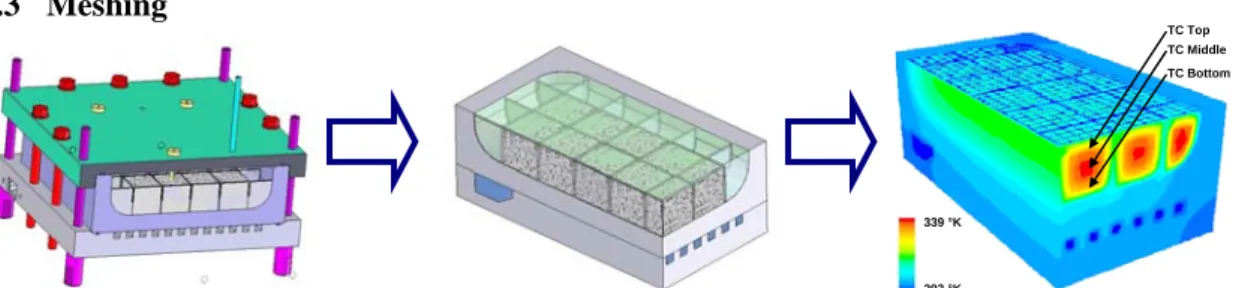
5.3 Meshing 339 °K 293 °K TC Top TC Middle TC Bottom
The design of the tank has been integrated in the Fluent software from SolidWorks and the metal hydride behaviour has been integrated in the numerical tool.
6 Simulation results
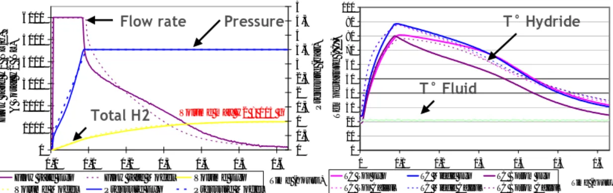
The simulation results are shown in Figure 6. The experimental and simulation results are quite similar so the simulation tool have been validated.
0 1000 2000 3000 4000 5000 6000 0,0 0,1 0,2 0,3 0,4 0,5 0,6 Time (hours)
Flow rate H2 (NL/h) & Total H2 (NL)
0 0,5 1 1,5 2 2,5 3 3,5 4 4,5 5 Pressure (ba r)
Flow rate Exp Flow rate Model Volume Exp Volume Model Pressure Exp Pressure Model
0 10 20 30 40 50 60 70 80 90 100 0 0,1 0,2 0,3 0,4 0,5 0,6 Time (hours) Tem p e ra tur e ( °C )
TC Top Exp TC Middle Exp TC Bottom Exp
TC Top Calcul TC Middle Calcul TC Bottom Calcul
Flow rate Pressure T° Hydride
T° Fluid Total H2 Volume max H2 = 115 g
Figure 6 : Absorption cycle in constant pressure mode (left) and thermal responses inside the MH bed (right). The experimental results are plotted in full lines and the simulation results are
plotted in dotted lines. The Mass Flow meters are limited to 6000 NL/h.
Conclusions
A previous study: Iosub (2006) has led to the development of the composition MmNi5-xSnx for
which the reversible storage capacity was optimized (0.95 wt%) in a narrow pressure range (absorption 3.5 bar, desorption 1.5 bar) at 75°C.
This Metal Hydride has been charged in a Plate–fin type Metal Hydride tank with an effective storage capacity of 1.2 Nm³ (106 g) of Hydrogen.
The important characteristics of the Metal Hydride tank have been analyzed and the obtained performances fulfilled the objectives imposed by a Stationary Cogeneration System.
A numerical tool has been adapted to simulate the thermal and mass behaviour of the hydrogen tank. The simulation has been validated by the experiments done with the storage system. This numerical tool will be used to design future Metal Hydride Storage systems.
References:
Iosub, V., Latroche, M., Joubert, J-M., Percheron-Guégan, A. 2006 Optimisation of MmNi5-xSnx
(Mm=La, Ce, Nd and Pr, 0.27<x<0.5) compositions as hydrogen storage materials. Int J.
Hydrogen Energy, 31, 101-108.
Pons, M. 1991 Heat transfers in the LaNi5 powder coupled with hydrogenation reaction. Thesis from Paris 6 University.
Nasrallah, S.B., Jemni, A. 1995 Study of a two-dimensional heat and mass transfer during absorption/desorption in a metal-hydrogen reactor. Int J. Hydrogen Energy, 20, Issue 1, 43-52.