HAL Id: cea-01235183
https://hal-cea.archives-ouvertes.fr/cea-01235183
Submitted on 28 Nov 2015
HAL is a multi-disciplinary open access
archive for the deposit and dissemination of
sci-entific research documents, whether they are
pub-lished or not. The documents may come from
teaching and research institutions in France or
abroad, or from public or private research centers.
L’archive ouverte pluridisciplinaire HAL, est
destinée au dépôt et à la diffusion de documents
scientifiques de niveau recherche, publiés ou non,
émanant des établissements d’enseignement et de
recherche français ou étrangers, des laboratoires
publics ou privés.
A simulation framework for rapid prototyping and
evaluation of thermal mitigation techniques in
many-core architectures
Tanguy Sassolas, Chiara Sandionigi, Alexandre Guerre, Julien Mottin, Pascal
Vivet, Hela Boussetta, Nicolas Peltier
To cite this version:
Tanguy Sassolas, Chiara Sandionigi, Alexandre Guerre, Julien Mottin, Pascal Vivet, et al.. A
simu-lation framework for rapid prototyping and evaluation of thermal mitigation techniques in many-core
architectures. 2015 IEEE/ACM International Symposium on Low Power Electronics and Design
(ISLPED), Jul 2015, Rome, Italy. �10.1109/ISLPED.2015.7273485�. �cea-01235183�
A Simulation Framework for Rapid Prototyping and
Evaluation of Thermal Mitigation Techniques in
Many-Core Architectures
Tanguy Sassolas
∗, Chiara Sandionigi
∗, Alexandre Guerre
∗, Julien Mottin
†,
Pascal Vivet
†, Hela Boussetta
‡, Nicolas Peltier
‡∗ CEA, LIST, 91191 Gif-sur-Yvette CEDEX, FRANCE - Email: [email protected] † CEA, LETI, Minatec Campus, Grenoble, FRANCE - Email: [email protected]
‡ DOCEA Power, 166 rue du Rocher de Lorzier 38430 Moirans, FRANCE - Email [email protected]
Abstract—Modern SoCs are characterized by increasing power density and consequently increasing temperature, that directly impacts performances, reliability and cost of a device through its packaging. Thermal issues need to be predicted and mitigated as early as possible in the design flow, when the optimization opportunities are the highest. In this paper, we present an efficient framework for the design of dynamic thermal mitigation schemes based on a high-level SystemC virtual prototype tightly coupled with efficient power and thermal simulation tools. We demonstrate the benefit of our approach through silicon comparison with the SThorm 64-core architecture and provide simulation speed results making it a sound solution for the design of thermal mitigation early in the flow.
I. INTRODUCTION
Thanks to technology scaling, SoC designers have been able to pack more and more transistors into the same chip for the great benefit of the end user. Unfortunately, this scaling in size is not equally matched by a scaling in power consumption, resulting in an increase in junction temperature. Such increase has negative impacts on the system reliability through the acceleration of both mechanical (e.g., thermal cycling) and electro-chimical phenomena (e.g., electromigration and neg-ative bias temperature instability). It can also impact system performances as the power budget must be distributed among the processing resources. This means that some resources must be kept powered down for others to work at their peak power consumption; this is referred to as dark silicon. Dynamically balancing the power consumption of processing resources is now a necessity. For many-core architectures, this is often managed by online scheduling techniques. To validate that a system can provide enough processing power while respecting its power and thermal budget, such scheduling techniques shall be developed as early as possible in the flow. Efficient thermal simulation frameworks that take into account the complete behavior of the system are required to enable the development of dynamic thermal mangement.
To be able to develop applications for architectures that are still under design, software designers usually rely on Vir-tual Prototypes (VPs). Accurate VPs are efficient to simulate an architecture’s behavior for small periods of times in the time scale of an application’s length. However, temperature phenomena timescale ranges from an order of magnitude of few milliseconds up to hours. Simulation time of accurate VPs would drastically soar if they were to be used for thermal evaluation. As a result, accurate VPs fail to encompass thermal issues. The challenge consists in realizing the thermal model and analysis of many-core architectures at high abstraction level and in evaluating dynamic thermal management tech-niques early in the design flow.
In this paper, we propose a framework based on a high-level VP executing real-case applications and tightly coupled with modeling and simulation tools for power and temperature. We study the simulation speed reached by this framework and characterize the accuracy of the thermal simulations with physical measures on a 64-core MPSoC architecture. Finally, we illustrate the benefit of our framework for the development of dynamic thermal mitigation schemes on this architecture.
II. RELATED WORK
A considerable amount of research has gone into devel-oping thermal simulation tools. Here, the focus is on tools that allow the evaluation of dynamic thermal management techniques on many-core architectures early in the design flow. Various multiphysics simulation tools, like FloTHERM (Mentor Graphics) and Icepak (ANSYS), have been proposed to realize fine-grain and accurate estimation of thermal effects. Such tools work at too low abstraction level and are charac-terized by long simulation times. The simulation speed is a requirement for the purposes of this paper to execute various thermal management techniques. Hence, higher abstraction levels are considered.
Two of the most popular architecture-level thermal sim-ulators are HotSpot [1] and 3D-ICE [2]. These tools cannot be directly adopted for the evaluation of dynamic thermal management techniques unless adequate extensions are made (for example, to evaluate the thermal impact on power) and the tools are coupled with VPs. Various works have realized such extensions and coupling with other tools. An example of integration of HotSpot in a multi-core simulation environment is found in [3]. This work presents two main drawbacks. First, the estimation of the temperature is typically based on steady-state analysis, that approximates the thermal behavior by its steady-state temperature. It can easily be shown that the use of the steady-state temperature might lead to wrong assumptions about the thermal behavior of an application. The approach is not appropriate for the evaluation of dynamic techniques. The second drawback is related to the number of cores. In fact, most of the works in literature analyzes architectures with few cores and do not extend the analysis to many-core architectures. Hence, the capability of modeling architectures with several cores and the achieved simulation speed are not evaluated. An example of integration of 3D-ICE in a simulation environment is found in [4]. Also this work considers an architecture with few cores and does not extend the analysis to the many-core case.
Few works have looked at a large number of cores. The work presented in [5] is one of the firsts proposing a thermal
Fig. 1. The proposed simulation framework, relying on three tools for thermal, power and functional aspects
modeling approach for many-core architectures. Its aim is the optimization of various design variables (CPU count, pipeline depth, superscalar width, etc.) by taking into account thermal constraints. Steady-state power at the granularity of each core is used to estimate steady-state thermal effects. Again, the drawback of the work with respect to the purposes of this paper is that the approach can not be adopted for dynamic thermal management techniques.
The work closest to the one proposed in this paper has been presented in [6]. It realizes the power and thermal simulation of a multi-core architecture at functional level with the objective of developing thermal mitigation schemes. The main limit with respect to the work proposed in this paper is the lack of validation of the obtained results. Moreover, the focus is on the architecture’s model and no simulation flow is presented. Also when considering the modeling part, the selected architecture is composed of four cores and no evaluation is made about the effort necessary for the modeling of many-core architectures and the achieved simulation speed.
To conclude, with respect to the state of the art, the proposed work presents two main contributions: i) Early eval-uation of dynamic thermal management techniques on many-core architectures and ii) validation of the proposed framework by comparing the results with the ones obtained on silicon.
III. SIMULATION FRAMEWORK
As illustrated in Figure 1, the simulation framework we propose relies on three tools : a thermal modeling tool, Ther-mal Profiler [7], that provides a Dynamic Compact Thermal Model (DCTM) of the system, a power and thermal simulation tool, Aceplorer [7], that provides a power model of the system dependent on its activity, and a functional simulation tool that provides application-dependent activity information to Aceplorer. There is a clear separation between the three aspects of the dynamic thermal behavior of a SoC: functional, power and thermal.
A. Thermal modeling
Thermal Profilertakes as input a geometric description of the complete physical system (die, package, board, environ-ment) using rectangular cuboids of homogeneous materials. The thermal properties (density, 3-axes thermal conductivity and specific heat capacity) of the base material are known. For
every power consumption source of the system, a 2D dissipa-tion surface is assumed. As a result, the physical descripdissipa-tion of dissipating elements is a rectangular shape on a cuboid face. For instance, the power dissipation of a SoC is represented as a set of rectangular shapes, representing the IP floorplanning, on top of a cuboid of silicon. Thermal probes are described as punctual 3D coordinates anywhere in the system.
This physical description is automatically meshed by Ther-mal Profiler to obtain the thermal model of the system as a network of thermal resistances and capacitances. The more accurate the description is, the thinner the mesh and the more complex the resulting network. To be efficiently exploited in designing thermal mitigation schemes, the complexity of the thermal model must be kept as little as possible to improve the simulation speed. As a result, Thermal Profiler integrates a Model Order Reduction (MOR) technique that automatically processes the thermal network and produces a DCTM.
For a fast and efficient reduction, material homogenization techniques shall be used to abstract geometry details while preserving their impact on the system. Thermal Profiler offers a specific homogenization API to select cuboids and merge them altogether. Thanks to it, the user can homogenize details that are far away from observed components while keeping accuracy on close details.
B. Power and thermal simulation
Aceplorer is used both to model the power behavior of the system and to simulate its power and thermal behavior. A component power model is composed of one or more power states which form a Power State Machine (PSM). For every power state, the user provides an analytical model for both static and dynamic consumptions. The analytical model can be dependent on any functional aspect through programmable variables, should it be the DVFS operating point or the number of accesses to a memory. The power model of a system is a hierarchical set of component power models. A DCTM created with Thermal Profiler can be associated to a power model for thermal evaluation. The association consists in declaring which component dissipates on which dissipating area of the physical description. The power model can also take into account the impact of the temperature on the static or dynamic power consumption. As a result thermal runaway phenomena can be observed.
To study the power and thermal behavior of application cases, static scenarios can also be described in the tool. They consist in timed succession of power state changes and pro-grammable variables values set up. To describe more dynamic behaviors, the state changes and the programmable variables can originate from a VP through a specific co-simulation link. The resulting power and temperature can also be sent back to the VP. To efficiently match power components to functional components, a python mapping script is used.
C. Functional simulation
For a timed functional SystemC model using Instruction Set Simulators (ISS), the usual simulation speeds are of the order of a few MISPS (Million Instruction Simulated per Second). For a single core architecture functioning at 1GHz, this means that it requires around 20 minutes to simulate a 1
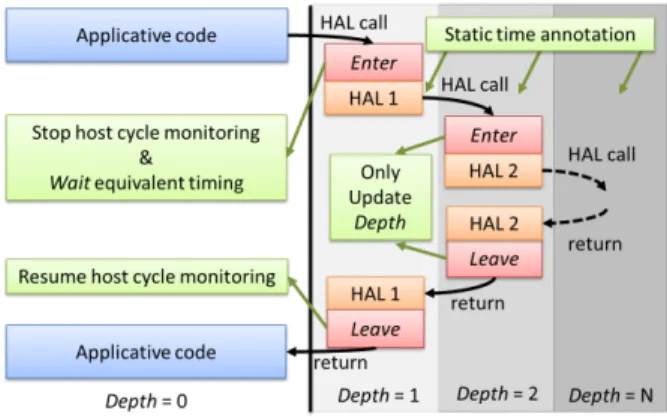
Fig. 2. High-level functional simulator timing annotation method. The applicative code is timed according to host cycles while HAL code is statically timed. The Enter and Leave functions monitor the HAL call depth to apply the correct timing method.
second long scenario. When moving to multi-core platforms, this simulation speed is spread among the processors (at least the active ones). This leads to a drastic increase in functional simulation time, that can reach a few hours for one simulated second. Thus, functional SystemC models are too slow for thermal simulation whose timescale evolves between few mil-liseconds and several hours. For thermal simulation purposes, the accuracy of a VP needs to be traded for simulation speed so as not to impede the overall simulation length. As a result, the functional simulator used in the dynamic thermal mitigation framework is a very abstract one targeting simulation speed at the cost of accuracy. Despite the behavioral timing error introduced by the model on the resulting power consumption, the thermal simulation (which to some extent integrates the power consumption along with time) shall output a correct estimated thermal behavior. Note that our simulator is not meant to replace time-accurate prototypes for performance and validation but rather to complement them for fast thermal evaluation purposes.
The high-level SystemC simulator used in our framework is abstract. All the simulated application and runtime code are executed directly on the x86 host. Every processing element is modeled by an independent SystemC thread that directly integrates the applicative code. The application code being executed natively by the host, its duration is derived from host execution time. The x86 cycles are monitored during the execution using the Read Time Stamp Counter (RDTSC) instruction. The target processor cycles are extrapolated using a rule-of-thumb based on processor’s known Instructions Per Cycles (IPC). The model also takes into account the current DVFS mode in this calculation. All Hardware Abstraction Layer (HAL) functions must be implemented on top of the host operating system. As a result, they must not be monitored like the rest of the applicative code as they do not represent the simulated architecture’s behavior. Instead, for these HAL functions, durations are annotated statically with wait state-ments. To obtain these HAL durations, rough estimations can be used during first design phases but they are to be replaced by more accurate timings obtained from time accurate prototypes such as [8], as was done in this study. Data accesses cannot be accurately taken into account at this level of description. Based on the estimated executed instructions and usual cache miss
rates, the impact of distant memory accesses, whose average latency is known, can be modeled on average.
The implementation of this timing methodology is depicted in Figure 2. Every HAL function is annotated so that it calls a prolog Enter function and an epilogue Leave function. The Enter function is responsible for stopping the host cycle counting and to commit the elapsed time up to this point in the application through a SystemC wait statement. It is necessary to commit the time immediately as HAL functions can implement synchronization mechanisms. All applicative threads must be kept synchronized during HAL. The Leave function is responsible of resuming the host cycle counting. When multiple HAL function calls are nested, only the first HAL calls to Enter and Leave have an effect. An HAL call depth counter is kept per thread to implement this behavior.
The AceTLMConnect SystemC monitoring library [7] is used to monitor and send functional activity data to Aceplorer and retrieve thermal temperature. It enables the monitoring of the simulated processor in terms of instruction counts, data access rates, voltage and frequency variations as well as power state changes. Data access rates monitoring cannot be used with our abstract environment. Synchronization between the SystemC simulator and Aceplorer can occur at the end of every SystemC timed update phase. As application threads execution length can greatly vary between two HAL functions calls, and the SystemC kernel time evolves with the speed of the slowest thread, the instruction counts exchanged corresponds to the proportion of the execution that was performed by all threads. To avoid too frequent simulation synchronizations, and thus power and thermal simulation steps, a minimum simulated time between two synchronizations, MIN SYNCHRO TIME, can be set. Whenever co-simulation synchronizations occur, the state of all processing resources are exchanged, so the time before the next synchronization is reset. This MIN SYNCHRO TIME is ignored for power mode, frequency or voltage change to keep the power and thermal simulation as accurate as possible. Indeed, they have a strong impact on the power consumption of the processing element. The same applies to thermal sensor value read that forces a synchronization with Aceplorer to retrieve an up-to-date value.
IV. STHORM ARCHITECTURAL CASE
To highlight the benefit of our framework for the design and validation of thermal mitigation in many-core architectures, we used the 64-core SThorm architecture [9]. The architecture is a parallel processing accelerator composed of an STxP70 con-trol processor, called Fabric Concon-troller (FC), responsible for dispatching applications to 4 processing clusters sharing 256 KB of L2 memory. Every cluster is composed of an STxp70 controller, or Cluster Controller (CC), which dispatches tasks on 16 STxP70 processors connected to a 256KB local shared memory through a logarithmic interconnect. Efficient proces-sor synchronizations per cluster are enabled through the use of an Hardware Synchronizer (HWS) [10]. This allows the pro-cessor to go to idle mode while waiting for barriers and to be woken up by interrupt. Each cluster has its own frequency is-land and supports DFS (Dynamic Frequency Scaling) between 1 and 430 MHz, therefore the clusters are connected through an Asynchronous Network-on-Chip (ANoC). In terms of thermal monitoring, the architecture embeds an absolute thermal sensor
close to the FC and also contains 32 multi-probe sensors evenly spread on the architecture. These sensors consist of multiple ring-oscillators which can be used as relative thermal sensors [11]. In this section, we present how the SThorm architecture was modeled in our framework in terms of thermal, power and functional descriptions. Finally, we present the real application case and two thermal mitigations schemes that were developed thanks to our framework for the SThorm architecture. A. Thermal model
To generate the thermal model of SThorm, a physical description of the board has been made. The components have been modeled by indicating the position on the board, the geometry and the main material. The package and die of SThorm have been described with a more detailed view. This difference of details in the description of the components allows to reduce the complexity of the thermal model (and consequently the simulation time) while keeping accuracy on the architecture under analysis.
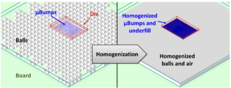
The package of SThorm is composed of nine layers of different materials and it lays on a grid of balls. On top of the package, the die lays on a grid of bumps. Every ball and bump have been described and the homogenization technique has been applied to reduce the complexity of the thermal model, as shown in Figure 3. In the die, also the floorplan of the many-core architecture has been described. The floorplan includes the position of the thermal sensors, necessary to get the temperature at the real sensors’ position.
Fig. 3. Impact of homogenization on the system’s physical description.
B. Power model
For the power model of SThorm, three types of components have been considered: generic IP, memory and processor. Each type of component is characterized by the values of leakage and dynamic power consumption, obtained through power analysis with PrimeTime PX (Synopsys), as done in [12]. The values are provided for three frequencies (10, 100 and 500 MHz) and values for other frequencies are computed by linear interpolation. The impact of the temperature on both leakage and dynamic currents has been modeled as follows: exp(βleak· (T − Tref)) for leakage and 1 + γdyn· (T − Tref)
for dynamic consumption. The βleak and γdyn coefficients
were respectively obtained through exponential and linear regressions from the power characterization data obtained for different temperature corner cases.
A power model has been created for each type of compo-nent. It is composed of power states, specifying leakage and dynamic currents. The power model of a generic IP (which is
any component of SThorm that is not a core or a memory) is the simplest model, since it has a single state. The memory model is composed of a state idle and states for read and write operations. The processor model is composed of a state active, a state stall and three states for low-power modes. The state active takes into account the various instructions and their impact on power.
C. Functional model
Using our high-level virtual prototyping methodology, the STHorm functional model consists of 64 SystemC threads, one per processing STxP70. Every processor contains a processing monitor allowing for the monitoring of its state. The processors are structured in clusters with a DFS functionality and a frequency monitor for power and thermal co-simulation. The HARS runtime was ported on top of an x86 linux, and every HAL function was extended with Enter and Leave functions to allow the timing of the application. A SystemC wait on event was used to model efficiently the wake up on interrupt feature per processor. The FC sensor and multiprobes HAL port were implemented to return the temperature estimated by Aceplorer and obtained via the co-simulation link.
D. Application case and thermal mitigations
To demonstrate the benefit of our approach on a real application case, we ported and parallelized a Human Body Detection and Counting (HBDC) on a SThorm cluster. The application utilizes a mixture of gaussian to determine the background image of a video sequence. Using this background, the application detects moving objects and, using a light-weight classification, determines if the object is a human. The background acquisition phase is performed in parallel using the RTM parallelisation pattern, while the classification is sequential. Due to the architecture of SThorm, only one cluster is used for the application. The other clusters execute con-volution products, which are representative of video pipeline pre-processing phases.
Two thermal mitigation schemes were developed for this ar-chitecture. The mitigation schemes were applied architecture-wise and not cluster-architecture-wise to observe significant changes in temperatures. The first one uses two frequency operating points: a low power frequency of 200 MHz and a nominal fre-quency of 400 MHz. The mitigation monitors the FC temper-ature sensor. If the tempertemper-ature crosses up a high tempertemper-ature threshold Thi of 59◦C, the low power frequency is used. If the
temperature crosses down a low temperature threshold Tlo of
55◦C, the nominal frequency is used. This method is a very basic reactive thermal mitigation scheme.
The second mitigation scheme uses the same monitoring and temperature thresholds but benefits from the wide fre-quency operating points of SThorm. The rationale is to use threshold crossing to lower or increase the used frequency point in a dichotomic fashion. The initial frequency is the nominal 400 MHz. If the FC temperature reaches Thi, then
the frequency is lowered by 400 MHz/2, i.e. it is set to 200 MHz. With this lower frequency, it might reach Tlo, then
the frequency would be increased by 400 MHz/4, i.e. it is set to 300 MHz. When the dichotomic step frequency delta 400 MHz/2n is too small, a 1 MHz delta is used instead.
This process goes on until the used frequency no longer hits any thresholds. This allows to reach the highest frequency that complies with the thermal boundaries. The temperature is expected to bounce between Thi and Tlo while slowly
converging towards a stable temperature. For both techniques the management was applied once every 100 frames.
In the next section, we study the benefit of our framework for the development of these thermal mitigations and in particular the simulation speed and accuracy of the estimated temperature.
V. RESULTS
A. Simulation speed
The simulation time is a key to enable an efficient de-velopment process for thermal mitigation schemes. In our framework, it is separated in two parts: the thermal simulation time and the functional simulation time.
The thermal simulation time is strongly impacted by the complexity of the DCTM used. Our detailed physical descrip-tion leads to a thermal model of 4.8 million nodes, which is too complex to be simulated. Using the homogenization technique, the model requires 7 times less nodes, but it leads to a too high simulation time. Hence, both the homogenization and reduction techniques have been exploited. Table I reports the number of nodes of the explored thermal models. When considering a scenario where all the processing elements execute a convolution product during 3000 s, the simulation time per step is 140 ms and the total execution time is 82 s. This DCTM is used for all subsequent results.
TABLE I. NUMBER OF NODES FOR DIFFERENT THERMAL MODELS
Thermal model Thermal model nodes No homogeneisation / No reduction 4, 883, 130 Homogeneisation / No reduction 664, 446 Homogeneisation & Reduction (DCTM) 888
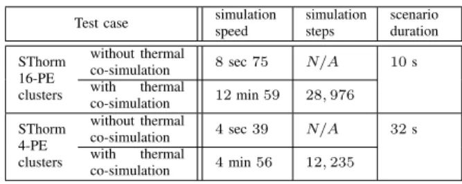
Also the functional simulation time can be a significant source of time waste. Table II shows the impact of the functional model on the overall simulation time. The results are shown for the execution of an HBDC application on the SThorm architecture without any mitigation for the processing of 1500 frames. The high-level model, when used without thermal co-simulation, is extremely fast and represents less than 10 seconds. However, when the thermal simulation is coupled with the functional simulator, the overall execution time reaches 13 minutes. This is due to a strong increase in the number of thermal simulation steps. In fact, to avoid loss of accuracy, one thermal simulation step is necessary whenever the power consumption state of a processor changes. This is highly dependent on the scenario and the complexity of the architecture. The more the processor switches of power state, the longer the simulation. The more processors there are in a given MPSoC architecture, the more likely these processors will switch state. For the HBDC application, we show that reducing the number of processors in SThorm clusters to 4 results in almost 8 times faster overall simulation duration per simulated second. We are currently working for introducing in our framework some constrained loss of accuracy in the power behavior to allow faster thermal simulation when scaling up the processing resources. However, the simulation durations we
reached are acceptable for efficient development of dynamic thermal mitigation schemes.
TABLE II. MANYCORE ARCHITECTURE IMPACT ON THERMAL
SIMULATION SPEED
Test case simulationspeed simulationsteps scenarioduration SThorm
16-PE clusters
without thermal
co-simulation 8 sec 75 N/A 10 s with thermal co-simulation 12 min 59 28, 976 SThorm 4-PE clusters without thermal
co-simulation 4 sec 39 N/A 32 s with thermal
co-simulation 4 min 56 12, 235
B. Silicon qualification
To be able to rely on thermal simulation tools, the user needs to be confident on the accuracy of the obtained results. Consequently, we qualified the accuracy of our models by comparing the temperature obtained through simulation and through physical measures. We used the SThorm on-chip FC sensor located at the center of the die to obtain the reference temperature. This sensor has a tolerance of +/-5◦C. Multi-probe sensors’ results, though relative and noisier, confirm the FC measures and are therefore not shown here. The ambient temperature was measured and the thermal simulation initial conditions were set accordingly. We plan to continue this qualification of the whole die surface through Infra-Red (IR) imaging.
Figure 4 shows the evolution of the SThorm FC tem-perature for a static activity scenario. All the processing elements execute loops of convolution product at 400MHz. This is a peak power consumption scenario, which allows to study simultaneously the temperature range of SThorm and the transient evolution inherent to the packaging. When looking at a long scale view of this measure in log scale (Figure 4a), we show that the absolute temperature error is limited to 5◦C, which is the same tolerance of the FC sensor. As a result in terms of amplitude, the thermal model is as accurate as our measure allows it to be. The main limitation is that the measured temperature may exceed the predicted one. Consequently, pessimistic assumptions could be used as needed. When looking at the transient behavior, best highlighted in linear scale (Figures 4b and 4c), we see that the DCTM modeling is accurate. Indeed, the transient behavior matches both a middle term thermal constant (with an order of magnitude of a few dozens of seconds) and a long term one (a few hundreds of seconds). The first time constant corresponds to the packaging heating time, the second one to the PCB heating time. The board heating time, with an order of magnitude of a few hours, can also be observed in Figure4a. For this time constant, the thermal model reaches the steady state before the measures, but the order of magnitude of the phenomena is preserved. The approximations made during the modeling of the board itself and the measurement conditions did not allow more accurate results.
The silicon qualifications obtained with a static thermal ramp-up scenario provide a good confidence in the amplitude and transient behavior of our thermal model. We now study how this qualification allows the development of dynamic thermal mitigation schemes. In Figure 5, we present the
25 30 35 40 45 50 55 60 65 70 1 10 100 1000 10000 Temperatur e [°C] Time [s] Simulation Measures (a) 25 30 35 40 45 50 55 60 65 70 0 5 10 15 20 Temperatur e [°C] Time [s] Simulation Measures (b) 25 30 35 40 45 50 55 60 65 70 0 100 200 300 400 500 600 Temperatur e [°C] Time [s] Simulation Measures (c)
Fig. 4. Evolution of SThorm die center temperature (Fabric Controller) from boot to steady state with a static scenario where all PEs execute convolution products @ 400 MHz in log scale (4a) and linear scale (4b & 4c).
temperature observed for the FC on board. For these measures, the HBDC application is executed on the 16 processors of one cluster while the other processors execute synthethic benchmarks corresponding to prefiltering steps of a video processing pipeline. The two mitigations schemes presented in IV-D are compared to the baseline execution without any mitigation. The lower temperatures allowed by the mitigation schemes are obtained at the cost of reduced Quality of Service (QoS) in the form of lost frames. Indeed, when the HBDC application is not executed at its nominal speed, it cannot cope with the camera frame rate and misses input frames (Table III). This can impact the tracking of human targets in the application and reduce the detection rate. The dichotomic frequency search reaches a better QoS on the long run as it tends to stabilize its throughput to the thermal conditions.
50 52 54 56 58 60 62 64 0 50 100 150 200 Temperatur e [°C] Time [s] Simple threshold Dichotomic frequency search No mitigation
Fig. 5. Thermal execution profiles for the die center temperature (FC) for
two mitigation schemes on board.
VI. CONCLUSION
In this paper, we presented an efficient framework for the design and validation of thermal mitigation schemes. In particular, this work focused on the specific issues of MPSoC
TABLE III. THERMAL MANAGEMENT QUANTITATIVE RESULTS
Mitigation case Maximal Temperature (◦C)
Skipped Frames No Management 65 None Simple thresholds 59 167/1500 Dichotomic frequency search 57 67/1500
architectures whose power behavior is highly dependent on the processors’ activity. The proposed framework allows fast thermal simulation of a many-core architecture executing a real case application in a few minutes. The thermal modeling homogeneization and reduction techniques used to obtain such simulation speed did not lead to a loss of accuracy in the predicted thermal behavior. Silicon measures on the 64-core SThorm architecture confirmed the accuracy of our framework for both amplitude and time scale. We demonstrated the benefit in terms of both speed and accuracy by using the framework to develop two thermal mitigations for the SThorm architecture. In the future, we plan to further analyze the accuracy of the thermal model using IR imaging on the surface of the SThorm die. With such information, we expect to reduce the temperature sensor inherent error. We also plan to extend the framework deeper in the flow by benefiting from emulation technique to refine the application behavior when RTL models are available.
REFERENCES
[1] W. Huang, S. Ghosh, S. Velusamy, K. Sankaranarayanan, K. Skadron,
and M. Stan, “Hotspot: a compact thermal modeling methodology for early-stage vlsi design,” IEEE Transactions on Very Large Scale Integration Systems, vol. 14, no. 5, pp. 501–513, 2006.
[2] A. Sridhar, A. Vincenzi, M. Ruggiero, T. Brunschwiler, and D. Atienza,
“3d-ice: Fast compact transient thermal modeling for 3d ics with inter-tier liquid cooling,” in IEEE/ACM Int. Conf. on Computer-Aided Design (ICCAD), 2010, pp. 463–470.
[3] M. Monchiero, R. Canal, and A. Gonz´alez, “Design space exploration
for multicore architectures: A power/performance/thermal view,” in Int. Conference on Supercomputing, 2006, pp. 177–186.
[4] M. Sadri, M. Jung, C. Weis, N. Wehn, and L. Benini, “Energy
opti-mization in 3d mpsocs with wide-i/o dram using temperature variation aware bank-wise refresh,” in DATE, 2014, pp. 1–4.
[5] Y. Li, B. Lee, D. Brooks, Z. Hu, and K. Skadron, “Impact of thermal
constraints on multi-core architectures,” in Intersociety Conference on Thermal and Thermomechanical Phenomena in Electronics Systems (ITHERM), 2006, pp. 139–146.
[6] T. Sassolas, C. Sandionigi, A. Guerre, A. Aminot, P. Vivet, H. Boussetta,
L. Ferro, and N. Peltier, “Early design stage thermal evaluation and mitigation: The locomotiv architectural case,” in DATE, 2014, pp. 1–2.
[7] [Online]. Available: http://www.doceapower.com
[8] N. Ventroux et al., “SESAM: A Virtual Prototyping Solution to
De-sign Multicore Architectures,” in Multicore Technology: Architecture, Reconfiguration, and Modeling, 2013, pp. 61–104.
[9] L. Benini, E. Flamand, D. Fuin, and D. Melpignano, “P2012: Building
an ecosystem for a scalable, modular and high-efficiency embedded computing accelerator,” in DATE, 2012, pp. 983–987.
[10] F. Thabet, Y. Lhuillier, C. Andriamisaina, J.-M. Philippe, and R. David,
“An efficient and flexible hardware support for accelerating synchro-nization operations on the sthorm many-core architecture,” in DATE, 2013, pp. 531–534.
[11] L. Vincent, P. Maurine, S. Lesecq, and E. Beigne, “Embedding statistical
tests for on-chip dynamic voltage and temperature monitoring,” in Design Automation Conference (DAC), 2012 49th ACM/EDAC/IEEE, June 2012, pp. 994–999.
[12] T. Ducroux, G. Haugou, V. Risson, and P. Vivet, “Fast and accurate
power annotated simulation: Application to a many-core architecture,” in Int. Workshop on Power and Timing Modeling, Optimization and Simulation (PATMOS), 2013, pp. 191–198.